Engstrom
CARESCAPE Monitors
CARESCAPE MP100 series Telemetry Server Service Manual Sw Ver 4.2 Oct 2010
Service Manual
196 Pages
Preview
Page 1
GE Healthcare
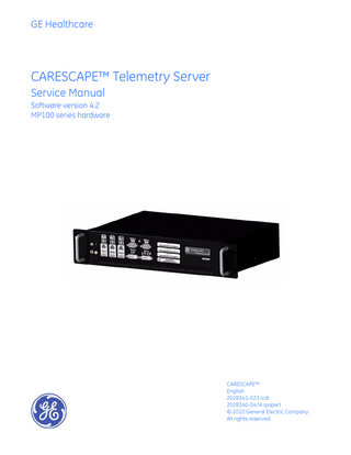
CARESCAPE™ Telemetry Server Service Manual Software version 4.2 MP100 series hardware
CARESCAPE™ English 2028341-023 (cd) 2028340-047A (paper) © 2010 General Electric Company. All rights reserved.
NOTE The information in this manual only applies to CARESCAPE Telemetry Server running ApexPro® Host software versions 4.2 or later. Due to continuing product innovation, specifications in this manual are subject to change without notice. NOTE For technical documentation purposes, the abbreviation GE is used for the legal entity name, GE Medical Systems Information Technologies, Inc. Listed below are GE Medical Systems Information Technologies, Inc. trademarks. All other trademarks contained herein are the property of their respective owners. APEX, APEXPRO, MUSE, and SOLAR are trademarks of GE Medical Systems Information Technologies, Inc. registered in the United States Patent and Trademark Office. CARESCAPE, CD TELEMETRY–LAN, CENTRALSCOPE, CIC PRO, EAGLE, Prism, TRAMSCOPE, and UNITY NETWORK are trademarks of GE Medical Systems Information Technologies, Inc.
T-2
CARESCAPE™
2001989-448A 25 October 2010
Contents 1
Introduction... 1-1 Manual information... 1-2 Manual purpose... 1-2 Intended audience... 1-2 Ordering manuals... 1-2 Related manuals... 1-2 Conventions used... 1-2 Illustrations and names... 1-3 Revision history... 1-4 Safety information... 1-4 Intended use... 1-4 Responsibility of the manufacturer... 1-4 Safety statements... 1-4 Equipment symbols... 1-7 Service requirements... 1-10 Equipment identification... 1-11
2
Equipment overview... 2-1 CARESCAPE Telemetry Server equipment description... 2-2 Telemetry Server... 2-2 Peripheral components... 2-4 CARESCAPE Network description/connection... 2-5 CARESCAPE Network MC... 2-5 CARESCAPE Network IX... 2-6 CARESCAPE Network RX... 2-6 Theory of operation... 2-6 ApexPro Telemetry System... 2-6 CARESCAPE Telemetry Server - MP100R... 2-7 ApexPro towers... 2-8 Receiver sub-system... 2-8 Antenna system... 2-8 CDT-LAN installations... 2-8 Access points... 2-9 Transmitter (channelized)... 2-9 FH transceiver... 2-9 CARESCAPE Network device communication... 2-9 Admit/TTX master... 2-10 Receiver configuration... 2-10 Sequence of events when admitting a patient... 2-12
2001989-448A
CARESCAPE™
i
3
Service interfaces... 3-1 Service logons... 3-2 Configure the service PC... 3-2 Configure the IP address... 3-3 Configure the Internet browser... 3-4 Access the telemetry server desktop... 3-4 Webmin service interface... 3-7 Log onto the Webmin service interface... 3-7 Webmin tab overview... 3-8 Change password for biomed user... 3-12 View the Telemetry Server software versions... 3-12 Telemetry Server software utilities... 3-13 Bed Duplicator... 3-13 Unity Viewer application... 3-16 ApexPro PTSCONFIG utility... 3-18
4
Installation... 4-1 Prerequisites... 4-2 Complete product training... 4-2 Complete site survey... 4-2 Service PC... 4-2 Pre-installation checklist... 4-2 Gather required tools... 4-3 Inspect equipment... 4-3 Evaluate site... 4-3 Installation process checklist... 4-7 Telemetry server installation precautions... 4-7 Mount the telemetry server... 4-8 Restrictions... 4-10 Connect the network cables... 4-10 CARESCAPE Network MC connection... 4-11 CARESCAPE Network IX connection... 4-11 CARESCAPE Network RX connection... 4-11 Power up... 4-11
5
Configuration... 5-1 ApexPro Telemetry System configuration... 5-2
ii
CARESCAPE™
2001989-448A
Process overview... 5-2 Access the telemetry server... 5-2 Configure the telemetry server... 5-2
6
Checkout procedures... 6-1 Overview... 6-2 Check the language settings... 6-3 Check status of all telemetry towers... 6-3 View system information... 6-5 Check Remote Service agent settings... 6-5 Check drive operation information (flash drive)... 6-6 Check speaker status... 6-7 Check processor fan status... 6-8 Check internal hardware temperature and voltage status... 6-8 Check BIOS information... 6-9 Check video function and status of video card and drivers... 6-10 Check operation of the Watchdog countdown function... 6-11 ApexPro Telemetry System - Channelized receiver check... 6-12 Back up the configuration settings... 6-13
7
Troubleshooting... 7-1 Hardware fault isolation... 7-2 Visual inspection... 7-2 Boot failure... 7-3 Telemetry server connection failure... 7-4 Component troubleshooting... 7-8 Troubleshooting... 7-8 Hardware monitoring utilities... 7-10 Network diagnostics... 7-10 Device Master statistics... 7-12 Check status of all telemetry towers... 7-16 Check read and write integrity of flash drive... 7-16 ApexPro Telemetry System - Channelized receiver check... 7-18 Receiver subsystem diagnostics... 7-19 Accessing service utilities... 7-23 Safe shutdown/restart of the telemetry server... 7-24 Telemetry server log files... 7-25 Navigate to log files... 7-25 Download system logs... 7-25 View application logs... 7-26 View OS event logs... 7-27 View OS Dr. Watson Log... 7-28 View log files - Webmin activity... 7-28
2001989-448A
CARESCAPE™
iii
8
Field replaceable units (FRUs)... 8-1 Rack-mount exploded views... 8-2 Interconnect diagram... 8-4 FRUs... 8-4 Disaster recovery software kit... 8-4 Accessories... 8-4 Power cables... 8-5 Keyboard kits... 8-5 Replacement procedures... 8-6 Rack-mount assembly... 8-7 Common replacement procedures... 8-8 Replacing the CPU PCB (mother board)... 8-10 Replacing the CPU battery... 8-11 Replacing the flash drive... 8-11 Replacing the SATA drive cable... 8-12 Replacing the power supply... 8-13 Replacing the fan... 8-14 Replacing the dual speakers... 8-14 Replacing the fuse... 8-15 Re-assemble the cover... 8-15
9
Preventive maintenance... 9-1 Maintenance schedule... 9-2 Safety tests and checkout procedures... 9-2 Overview... 9-2 Test equipment... 9-3 Recommended tools... 9-3 Temporary bed transfer... 9-3 Preventive maintenance checklist... 9-4 Visual inspection... 9-5 Disposal... 9-5 Cleaning... 9-6 Controlling electrostatic discharge damage... 9-9 Electrical safety tests... 9-10 General... 9-10 Recommendations... 9-10 Power outlet test... 9-11 Ground (earth) integrity... 9-11
iv
CARESCAPE™
2001989-448A
Ground (earth) wire leakage current tests... 9-12 Enclosure (chassis) leakage current test... 9-13 Test completion... 9-14 Perform preventative maintenance of UPS... 9-14 Perform preventive maintenance checkout procedures... 9-14 Access log files... 9-15
10
Reload software... 10-1 Purpose... 10-2 Process overview... 10-2 Gather required equipment and tools... 10-3 Create a CARESCAPE Telemetry Server image restore USB memory stick . . 10-3 Reload CARESCAPE Telemetry Server software... 10-5 Confirm images restored to correct drives... 10-6 Complete the configuration checkout procedures... 10-6 Reload process troubleshooting... 10-7 Incorrect boot order... 10-7 Software image on USB stick does not match hardware... 10-7 Additional troubleshooting... 10-8
11
Upgrade software... 11-1 Overview... 11-2 Establish alternate monitoring methods... 11-3 Gather the required equipment... 11-3 Prepare the CARESCAPE Telemetry Server... 11-3 Prepare the service PC... 11-4 Connect the service PC to the CARESCAPE Network IX network... 11-4 Start the software transfer utility... 11-4 Enter the CARESCAPE Network IX network addresses of CARESCAPE Telemetry Servers to be updated... 11-5 Install the software on the target CARESCAPE Telemetry Servers... 11-7 Activate the software packages... 11-9
2001989-448A
CARESCAPE™
v
Complete the checkout procedures... 11-10
A
Electromagnetic compatibility... A-1 Electromagnetic compatibility (EMC)... A-2 Guidance and manufacturer’s declaration... A-2 Electromagnetic emissions... A-2 Electromagnetic immunity... A-3 Recommended separation distances... A-5 Compliant cables and accessories... A-6
B
Device compatibility... B-1 Compatible devices... B-2
vi
CARESCAPE™
2001989-448A
1
2001989-448A
Introduction
CARESCAPE™
1-1
Introduction
Manual information Manual purpose This manual supplies technical information for service representatives and technical personnel so they can install, configure, troubleshoot and maintain the equipment. Use the manual as a guide for maintenance and electrical repairs considered field repairable. Where necessary, this manual identifies additional sources of relevant information and technical assistance.
Intended audience This manual is intended for use by authorized GE service representatives and authorized technical personnel who maintain, troubleshoot, or repair this equipment.
Ordering manuals A paper copy of this manual will be provided upon request. Contact your local GE representative and request the part number on the first page of the manual.
Related manuals
ApexPro Telemetry System Operator’s Manual
CARESCAPE Telemetry Server Technical Specifications Supplement, MP100R platform
Conventions used Equipment terms This manual uses the following terms to simplify common equipment names. Term
1-2
Description
CIC Pro center
Refers to the CIC Pro Clinical Information Center.
CARESCAPE Telemetry Server
Refers to the CARESCAPE Telemetry Server running ApexPro Telemetry host software.
Telemetry Server
Refers to the Telemetry Server running ApexPro Telemetry host software.
Transmitter
Refers to an Apex, ApexPro, ApexPro CH, or CARESCAPE Telemetry T14 transmitter.
Transceiver
Refers to an ApexPro FH transceiver.
ApexPro Telemetry Server (ATS)
Refers to the existing ApexPro Telemetry Server hardware platform running ApexPro Telemetry host software.
CARESCAPE™
2001989-448A
Introduction
Term
Description
Telemetry System
Refers to the complete ApexPro Telemetry System, comprised of transmitters, transceivers, antenna infrastructure, access points, receiver sub-system and the telemetry server. See ApexPro Telemetry System on page 26
Telemetry tower
For ApexPro Telemetry channelized systems, refers to a combination of telemetry server and receiver subsystem it is connected to. See ApexPro towers on page 2-8. NOTE For ApexPro Telemetry FH systems there is no physical receiver subsystem connected. The ApexPro Telemetry FH Server has built in tower functionality, hence the telemetry server serves as the telemetry tower.
Receiver subsystem
Refers to the hardware that encloses the patient receiver cards that receives, demodulates, and decodes patient data received through the antenna system from the transmitter. See Receiver sub-system on page 2-8.
ApexPro Telemetry host software
This is the ApexPro Telemetry software application that runs on the ApexPro Telemetry Server hardware.
Text styles Bold
Indicates keys on the keyboard, text to be entered, or hardware items such as buttons or switches on the equipment.
Bold and italics
Indicates software terms that identify menu items, buttons, or options in various windows.
Italics
Emphasizes a word.
+
Indicates a keyboard operation. A plus (+) sign between the names of two keys indicates that you must press and hold the first key while pressing the second key once. For example, Ctrl+Esc means to press and hold down the Ctrl key while pressing the Esc key.
>
Indicates menu options or control settings to select consecutively.
<Space>
Indicates you must press the spacebar. When instructions are given for typing a precise text string with one or more spaces, the point where the spacebar must be pressed is indicated as <Space>.
Enter
Indicates you must press the Enter or Return key on the keyboard. Do not type enter.
Illustrations and names This manual uses illustrations as examples only. Illustrations in this manual may not necessarily reflect all system settings, features, configurations, or displayed data. Names of persons, institutions, and places and related information are fictitious; any similarity to actual persons, entities, or places is purely coincidental.
2001989-448A
CARESCAPE™
1-3
Introduction
Revision history Each page of this manual has the document part number and revision letter at the bottom of the page. The revision letter identifies the document’s update level. The revision history of this document is summarized below. Revision A
Comment Initial release of document.
Safety information Intended use The ApexPro Telemetry System is intended for use under the direct supervision of a licensed healthcare practitioner. The system is designed to acquire and monitor physiological data for ambulating patients within a defined coverage area. The system processes this physiological data to detect various ECG arrhythmia events and select physiological parameter limit violations. The ApexPro Telemetry System is intended to be installed in the hospital or clinical environment in order to provide clinicians with patient physiological data, while allowing for patient mobility. These systems are typically deployed in sub acute care areas in hospitals or clinical sites where patient mobility can enhance the effectiveness of the medical procedures administered. The physiological parameters monitored include ECG, non-invasive blood pressure, non-invasive temperature, and SpO2. The ApexPro Telemetry System is intended to provide ECG data via Ethernet to the computer platform for processing. The ApexPro Telemetry System is also intended to provide physiologic data over the Unity Network to the clinical information systems for display.
Responsibility of the manufacturer GE is responsible for the effects of safety, reliability, and performance only if:
assembly operations, extensions, adjustments, modifications, or repairs are carried out by persons authorized by GE;
the electrical installation of the relevant room complies with the requirements of the appropriate regulations; and
the device is used in accordance with the instructions for use.
Safety statements The terms danger, warning, and caution are used throughout this manual to point out hazards and to designate a degree or level of seriousness. Familiarize yourself with their definitions and significance.
1-4
Hazard is defined as a source of potential injury to a person.
CARESCAPE™
2001989-448A
Introduction
Danger indicates an imminent hazard, which, if not avoided, will result in death or serious injury.
Warning indicates a potential hazard or unsafe practice, which, if not avoided, could result in death or serious injury.
Caution indicates a potential hazard or unsafe practice, which, if not avoided, could result in minor personal injury or product/property damage.
Note provides application tips or other useful information to assure that you get the most from your equipment.
Dangers No danger statements apply to this product.
Warnings The following warnings apply to this product. WARNING ACCESSORIES (EQUIPMENT) - The use of accessory equipment not complying with the equivalent safety requirements of the device may lead to a reduced level of safety of the resulting system. Consideration relating to the choice shall include:
use of the accessory in the patient environment; and
evidence that the safety certification of the accessory has been performed in accordance to the appropriate UL/IEC/EN 60950 series safety standards for IT equipment.
WARNING ACCESSORIES (SUPPLIES) - To ensure patient safety, use only parts and accessories manufactured or recommended by GE.
WARNING EXPLOSION HAZARD - Do not use this equipment in the presence of flammable anesthetics, vapors or liquids. Severe burns/ injury can result.
WARNING LOSS OF ALARMS/DATA- The CARESCAPE Telemetry Server MP100R running ApexPro software v4.1 or v4.2 is clinically compatible with CIC Pro centers (BCM and Nightshade) running ApexPro v4.0 and above and ApexPro Telemetry Servers (ATS) running v4.0 and above. See Appendix B for device compatibility with other Unity devices.
2001989-448A
CARESCAPE™
1-5
Introduction
WARNING LOSS OF ALARMS/DATA - Do not load any software other than that specified by GE onto the CARESCAPE Telemetry Server. Installation of software not specified by GE can interfere with, or may cause damage to, the CARESCAPE Telemetry Server or loss or corruption of data.
WARNING LOSS OF FUNCTION/ALARMS/DATA - Do not connect any devices other than that specified by GE to the CARESCAPE Telemetry Server. Installation of devices not specified by GE may cause damage to the telemetry server, can interfere with its operation or cause loss or corruption of data.
WARNING LOSS OF MONITORING - If it is necessary to shut down the telemetry server or receiver subsystem, notify the site’s biomedical department to provide alternate bedside patient monitoring. See Establish alternate monitoring methods on page 11-3.
WARNING UNINTENTIONAL RADIO FREQUENCY (RF) INTERFERENCE - Unintentional RF interference could degrade the reliability and performance of the wireless data link. The facility must maintain an RF environment free from unintentional interference.
Cautions The following cautions apply to this product. CAUTION POWER REQUIREMENTS - If the installation of the equipment, in the USA, will use 240V rather than 120V, the source must be a center-tapped, 240V, single-phase circuit.
CAUTION RESTRICTED SALE - U.S. federal law restricts this device to sale by or on the order of a physician.
1-6
CARESCAPE™
2001989-448A
Introduction
CAUTION SUPERVISED USE - This equipment is intended for use under the direct supervision of a licensed health care practitioner.
Notes The following notes apply to this product. NOTE Patient environment is any volume in which intentional or unintentional contact can occur between patient and parts of the system or between patient and other persons touching parts of the system (IEC 60601-1-1). NOTE This device is not intended for home use.
Equipment symbols NOTE Some symbols may not appear on all equipment. Symbol
Description ATTENTION: Consult accompanying documents.
TYPE B APPLIED PART: Non-isolated applied part suitable for intentional external and internal application to the patient excluding direct cardiac application. [Medical Standard Definition:] Applied part complying with the specified requirements of IEC 60601-1 Medical Standards to provide protection against electric shock, particularly regarding allowable leakage current. TYPE BF APPLIED PART: Isolated (floating) applied part suitable for intentional external and internal application to the patient excluding direct cardiac application. “Paddles” outside the box indicate the applied part is defibrillator proof. [Medical Standard Definition:] F-type applied part (floating/isolated) complying with the specified requirements of IEC 60601-1 Medical Standards to provide a higher degree of protection against electric shock than that provided by type B applied parts. NOTE The rating of protection against electric shock (indicated by symbol for CF or BF) is achieved only when used with patient applied parts recommended by GE. TYPE CF APPLIED PART: Isolated (floating) applied part suitable for intentional external and internal application to the patient including direct cardiac application. “Paddles” outside the box indicate the applied part is defibrillator proof. [Medical Standard Definition:] F-type applied part (floating/isolated) complying with the specified requirements of IEC 60601-1 Medical Standards to provide a higher degree of protection against electric shock than that provided by type BF applied parts.
2001989-448A
CARESCAPE™
1-7
Introduction
Symbol
Description Writer door button.
Silence Alarm keyboard key.
CE mark.
This symbol indicates the date of manufacture of this device. The first four digits identify the year and the last two digits identify the month.
Fuse. Replace the fuse with a fuse of the same type and rating.
Power On and Off.
Medical Equipment. With Respect to Electric Shock, Fire and Mechanical Hazards Only, In Accordance with UL 60601-1, CAN/CSA C22.2 NO.601.1, and IEC 60601-1.
For Russia only: Russian GOST-R certification, where XXXX indicates the four digit certification body number determined by product.
USB connector port.
Ethernet connector port used to connect to the CARESCAPE Network (MC, IX, or RX Network) as indicated on the device.
Serial connector ports 1 and 2.
Digital Visual Interface - Integrated for primary video connection that supports digital and analog displays.
1-8
CARESCAPE™
2001989-448A
Introduction
Symbol
Description Digital Visual Interface - Digital for secondary video connection that supports digital displays only.
Speaker out connector port.
Power indicator.
This symbol indicates that the waste of electrical and electronic equipment must not be disposed as unsorted municipal waste and must be collected separately. Please contact the manufacturer or other authorized disposal company to decommission your equipment.
European authorized representative.
Manufacturer name and address.
Equipotential stud. A ground wire from another device can be tied here to ensure the devices share a common reference point.
CLASS I EQUIPMENT: EQUIPMENT in which protection against electric shock relies on both basic insulation and protective earth, such that exposed metal parts cannot become live in the event of basic insulation failure
2001989-448A
CARESCAPE™
1-9
Introduction
Symbol
Description NOTE The following symbols (required by China law only) are representative of what you may see on your equipment. The number in the symbol indicates the EFUP period in years, as explained below. Check the symbol on your equipment for its EFUP period. This symbol indicates the product contains hazardous materials in excess of the limits established by the Chinese standard SJ/T11363-2006 Requirements for Concentration Limits for Certain Hazardous Substances in Electronic Information Products. The number in the symbol is the Environment-friendly User Period (EFUP), which indicates the period during which the toxic or hazardous substances or elements contained in electronic information products will not leak or mutate under normal operating conditions so that the use of such electronic information products will not result in any severe environmental pollution, any bodily injury or damage to any assets. The unit of the period is “Year”. In order to maintain the declared EFUP, the product shall be operated normally according to the instructions and environmental conditions as defined in the product manual, and periodic maintenance schedules specified in Product Maintenance Procedures shall be followed strictly. Consumables or certain parts may have their own label with an EFUP value less than the product. Periodic replacement of those consumables or parts to maintain the declared EFUP shall be done in accordance with the Product Maintenance Procedures. This product must not be disposed of as unsorted municipal waste, and must be collected separately and handled properly after decommissioning. This symbol indicates that this electronic information product does not contain any toxic or hazardous substance or elements above the maximum concentration value established by the Chinese standard SJ/T11363-2006, and can be recycled after being discarded, and should not be casually discarded.
Service requirements Follow the service requirements listed below, and in the Preventive maintenance chapter of this manual.
1-10
Refer equipment servicing to GE authorized service personnel only.
Any unauthorized attempt to repair equipment under warranty voids that warranty.
It is the user’s responsibility to report the need for service to GE or to one of their authorized agents.
Failure on the part of the responsible individual, hospital, or institution using this equipment to implement a satisfactory maintenance schedule may cause undue equipment failure and possible health hazards.
Regular maintenance, irrespective of usage, is essential to ensure that the equipment is always functional when required.
CARESCAPE™
2001989-448A
Introduction
Equipment identification Every GE device has a unique serial number for identification. A sample of the information found on a serial number label is shown below.
### ## ## #### # #
A
B
C
D
E
F
Description A
product code1
B
year manufactured
C
fiscal week manufactured
D
production sequence number
E
manufacturing site
F
miscellaneous characteristic 1The product code for the CARESCAPE Telemetry Server MP100R
with v4.x is SEE.
2001989-448A
CARESCAPE™
1-11
Introduction
1-12
CARESCAPE™
2001989-448A