Test Instructions - Service Card
29 Pages
Preview
Page 1
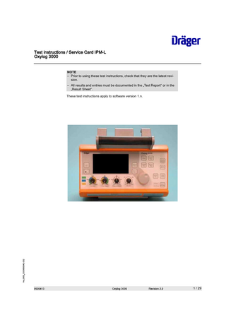
NOTE – Prior to using these test instructions, check that they are the latest revision. – All results and entries must be documented in the Test Report or in the Result Sheet. These test instructions apply to software version 1.n.
1 / 29
Table of contents
Table of contents 1 1.1
1.2
1.3
2 2.1 2.2 3 3.1
3.2
4 4.1
4.2
4.3 2 / 29
Device configuration 4 Oxylog device configuration... 4 1.1.1 Serial number (if not otherwise recorded) ... 4 1.1.2 Material number (if not otherwise recorded) ... 4 1.1.3 Software version ... 4 1.1.4 Device identification number (ID) ... 4 1.1.5 Tube type used ... 4 Software options Oxylog 3000 ... 5 1.2.1 O2 inhalation ... 5 1.2.2 100% O2... 5 1.2.3 O2 mixer ... 5 1.2.4 ASB/PS... 5 1.2.5 BIPAP/PCV+... 5 Device configuration, cylinder pressure regulator (if fitted)... 5 1.3.1 Cylinder pressure regulator used ... 5 1.3.2 Serial number ... 5 1.3.3 Alduk III validity... 6 Maintenance parts 6 Maintenance parts, every 2 years... 6 2.1.1 Service set... 6 Maintenance parts, every 6 years... 7 2.2.1 Service set... 7 Electrical safety 7 Electrical safety to DIN EN 62353 (IEC 62353) ... 8 3.1.1 Visual inspection of power supply unit... 8 3.1.2 Protective conductor of power supply cable ... 8 3.1.3 Visual check of MCable-Mainstream CO2 sensor (Oxylog 3000 plus only) ... 9 3.1.4 Device leakage current measuring points ... 9 3.1.5 Device leakage current ... 10 Electrical safety according to IEC 60601 ... 12 3.2.1 Visual inspection of power supply unit... 12 3.2.2 Protective conductor of power supply cable ... 12 3.2.3 Visual check of MCable-Mainstream CO2 sensor (Oxylog 3000 plus only) ... 13 3.2.4 Measuring points for housing leakage current... 13 3.2.5 Housing leakage current... 14 Function and condition test 15 Basic device condition test... 15 4.1.1 Labels and instructions for use ... 15 4.1.2 Base unit externally ... 15 Calibration, flow and leak test ... 15 4.2.1 Calibration ... 15 4.2.2 Check inspiratory flow ... 16 4.2.3 Leak test (inspiratory side) and accuracy check of Pint sensor... 16 Base unit function ... 17
Table of contents
4.4
4.5 4.6 5 5.1
6
4.3.1 Keys and potentiometer ... 4.3.2 LEDs and screen... 4.3.3 Safety valve... 4.3.4 Device check ... 4.3.5 Volume-controlled ventilation ... 4.3.6 Voltage supply... 4.3.7 Supply pressure/emergency air valve ... Portable system option ... 4.4.1 Portable system condition ... 4.4.2 Leak test... 4.4.3 Validity and function of AGSS/AOS (if fitted)... 4.4.4 Alduk III function... Wall bracket option ... 4.5.1 Condition and function... Final action ... 4.6.1 Device handover with test label... Test equipment Test equipment ... 5.1.1 Test equipment subject to mandatory calibration... 5.1.2 Test equipment not subject to mandatory calibration ... Annex
17 17 18 18 18 19 20 20 20 20 21 21 23 23 23 24 24 24 24 26 27
3 / 29
Device configuration
Oxylog device configuration
1
Device configuration This chapter is used to record the device configuration.
1.1
Oxylog device configuration
1.1.1
Serial number (if not otherwise recorded) Action
• Read the serial number from the rating plate.
Input
Serial number [________txt]
1.1.2
Material number (if not otherwise recorded) Action
• Read the material number on the rating plate.
Input
Material number [________txt]
1.1.3
Software version Action
• Read out and enter the software version later under Function and condition test (the software version is displayed on screen immediately after power-on).
Input
Software version [________txt]
1.1.4
Device identification number (ID) Action
• Read the device ID from the option label and enter it (the device ID can also be read from the CMS).
Input
Device ID [________txt]
1.1.5
Tube type used NOTE On the Oxylog 3000 plus and Oxylog 3000 (from software version 1.20) the tests can also be performed with paediatric tubing. Action
• Identify the type of tube with which the test is performed and confirm with OK.
Input
Reusable adult tubing [________OK]
Input
Disposable adult tubing [________OK]
Input
Paediatric tubing [________OK]
4 / 29
Device configuration
Software options Oxylog 3000
1.2
Software options Oxylog 3000 Prerequisites
1.2.1
Options available (available options are on the option sign)
O2 inhalation Result
Option available. [________OK]
1.2.2
100% O2 Result
Option available. [________OK]
1.2.3
O2 mixer Result
Option available. [________OK]
1.2.4
ASB/PS Result
Option available. [________OK]
1.2.5
BIPAP/PCV+ Result
Option available. [________OK]
1.3
Device configuration, cylinder pressure regulator (if fitted)
1.3.1
Cylinder pressure regulator used Input
Enter the cylinder pressure regulator used. [________txt]
1.3.2
Serial number Action
• Read the serial number.
Input
Enter the serial number. [________txt]
5 / 29
Maintenance parts
Maintenance parts, every 2 years
Read off the serial number from the Alduk III:
Fig. 1
Alduk III serial number
NOTE – The first two figures of the serial number indicate the year of manufacture. The next two figures indicate the month of manufacture (0901... = 2009, January). – Alduk I / II is to be tested as per the Alduk test instructions.
1.3.3
Alduk III validity NOTE – Alduk III is to be replaced after 10 years. – In the above illustration, the Alduk III would be usable up to and including January 2019. Action
• Based on the serial number, determine how much longer the Alduk III can be kept in service.
Input
Alduk III validity date [________txt]
2
Maintenance parts This chapter contains interval-related maintenance parts, measures, and tests that can only be performed on an open device.
2.1
Maintenance parts, every 2 years Prerequisites
2.1.1
None.
Service set The service set MX08755 (quantity 1) includes the following parts:
6 / 29
Quantity
Designation
Number
Location/Remark
1
Filter mat
2M86341
Base unit/Replacement by specialist
1
Rechargeable battery, lithium ion
2M86733
Base unit
Electrical safety
Maintenance parts, every 6 years
Quantity
Designation
Number
Location/Remark
2
Spirolog sensors
8403735 (5x)
Pneumatic assembly/Replacement by specialist
2
Cable tie
8712065
Pneumatic assembly/Replacement by specialist
Input
2.2
Next replacement: [________dat]
Maintenance parts, every 6 years Prerequisites
2.2.1
None.
Service set The service set MX08756 (quantity 1) includes the following parts:
Quantity
Designation
Number
Location/Remark
1
Filter mat
2M86341
Base unit/Replacement by specialist
1
Rechargeable battery, lithium ion
2M86733
Base unit
2
Spirolog sensors
8403735 (5x)
Pneumatic assembly/Replacement by specialist
2
Cable tie
8712065
Pneumatic assembly/Replacement by specialist
1
Battery and quartz
1851918
Only replaced in the Oxylog 2000 plus and Oxylog 3000. Control PCB/Replacement by specialist.
1
Pressure regulator
Input
3
2M86361
Pneumatic assembly/Replacement by specialist Next replacement: [________dat]
Electrical safety This chapter contains tests that need to be performed in order to verify that the medical electrical system is operational. 7 / 29
Electrical safety
Electrical safety to DIN EN 62353 (IEC 62353)
3.1
Electrical safety to DIN EN 62353 (IEC 62353) NOTE The Oxylog under test meets the conditions of protection class 2. Oxylog 3000 plus only: With the MCable-Mainstream CO2 sensor (sensor connected) the Oxylog 3000 plus corresponds to type BF. NOTE The tester, e.g. SECUTEST, must be correctly configured for all measurements (perform protective conductor test with setting Protection class I). If implausible measurement results are obtained, such as a leakage current of 0.0 µA, check the tester configuration in addition to the test setup! NOTE – In testing to IEC 62353, the medical electrical device (ME device) or the medical electrical system (ME system) must be tested. – ME systems must be treated like ME devices. – An ME system is a combination of several devices, as specified by the manufacturer, of which at least one must be an ME device, which are interconnected by a functional connection or by means of a multiple socket outlet. NOTE With devices that are connected to other devices by means of a data cable, this connection must be disconnected prior to performing the electrical safety check, in order to avoid incorrect measurements.
3.1.1
Visual inspection of power supply unit Test Result
The power supply unit, power supply cable and Oxylog connecting cable are not damaged or dirty. Condition checked. [________OK]
3.1.2
Protective conductor of power supply cable NOTE The AC/DC power supply unit conforms to protection class 2. The protective conductor resistance of the power cable must be checked.
8 / 29
Electrical safety
Electrical safety to DIN EN 62353 (IEC 62353)
Test set-up
Fig. 2
Test setup for protective conductor resistance
Item Designation
Action
1
Tester, e.g. SECUTEST
2
Power cable
3
Test probe with tip (e.g. SECUTEST accessories) or test adapter for connecting cable
4
Sockets for applied parts
L
Conductor
N
Neutral conductor
PE
(Protective earth) conductor
• Prepare the test setup. • Connect the test adapter or the tip of the test probe to the protective conductor contact of the connector (connector to the power supply unit), and then measure the protective conductor resistance (for the measurement, move the power supply cable section-by-section during the measurement).
Test Result
The value of the protective conductor resistance must not exceed 0.1 ohms. Protective conductor resistance [________Ohm]
3.1.3
Visual check of MCable-Mainstream CO2 sensor (Oxylog 3000 plus only) Test Result
The housing, cables and connectors of the MCable-Mainstream CO2 sensor are not damaged or dirty. Condition checked. [________OK]
3.1.4
Device leakage current measuring points NOTE The device leakage current test is performed without the device-specific test adapter. Oxylog 3000 plus only: The MCable-Mainstream CO 2 sensor is internally electrically isolated and has no metallic contacts.
9 / 29
Electrical safety
Electrical safety to DIN EN 62353 (IEC 62353) Action
• Check the following measuring points with the test probe when measuring the device leakage current: – Compressed gas connection – Claw (screws)
Input
Measuring points are known. [________OK]
3.1.5
Device leakage current NOTE – The device leakage current can be tested by the direct measurement method or the differential measurement method. – For direct measurement, set up the device under test so that it is insulated and scan all touchable conductive components using the probe. – Differential current measurements often produce different measured values from direct measurements.
Prerequisites
The tester is switched on.
Test set-up
Fig. 3
Device leakage current direct measurement
Item Designation
Action
1
Tester (test device)
2
Power supply unit
3
Medical device
4
(If applied part fitted) Device-specific test adapter for tester
5
(If applied part fitted) Configurable sockets for applied part
6
Test probe
L
Conductor
N
Neutral conductor
PE
Protective conductor
• Prepare the test setup. • (Applied part) Connect the device-specific test adapter on one end to the device under test and on the other end to the tester's configurable socket A for applied parts (paying attention to the configuration!). • Follow the instructions on the tester.
10 / 29
Electrical safety
Electrical safety to DIN EN 62353 (IEC 62353)
NOTE The measurement must be performed twice! The second test is performed with the plug rotated 180° in the socket. In many test devices the mains plug rotation is simulated by means of a built-in selector switch. The higher measured value must be documented. NOTE The reference value (initial measured value) must always be transmitted! NOTE If the measured values are between 90% and 100% of the permissible limit value, the reference value and the previously measured values of the recurrent test should be applied to assess electrical safety! Test Result
The reference value must not exceed 100 µA. Reference value [________µA]
Test Result
The recurrent test value must not exceed 100 µA. Recurrent test [________µA]
11 / 29
Electrical safety
Electrical safety according to IEC 60601
3.2
Electrical safety according to IEC 60601 NOTE The Oxylog under test meets the conditions of protection class 2. Oxylog 3000 plus only: With the MCable-Mainstream CO2 sensor (sensor connected) the Oxylog 3000 plus corresponds to type BF. NOTE The following presents a description of the electrical safety tests according to IEC 60601. Whether the standard is applicable or not depends on national regulations and its use must be decided on site under consideration of applicable national regulations. NOTE The tester, e.g. SECUTEST, must be correctly configured for all measurements (perform protective conductor test with setting Protection class I). If implausible measurement results are obtained, such as a leakage current of 0.0 µA, check the tester configuration in addition to the test setup! NOTE – When testing according to IEC 60601, systems must be tested and not individual devices. – Systems should be treated as devices. – A system is a combination of several devices of which at least one is a medical electrical device which is connected to other devices by functional connections or by a transportable multiple socket outlet. NOTE With devices that are connected to other devices by means of a data cable, this connection must be disconnected prior to performing the electrical safety check, in order to avoid incorrect measurements. NOTE The test to UL2601-1 is satisfied by testing to IEC 60601. Differing limit values are marked.
3.2.1
Visual inspection of power supply unit Test Result
The power supply unit, power supply cable and Oxylog connecting cable are not damaged or dirty. Condition checked. [________OK]
3.2.2
Protective conductor of power supply cable NOTE The AC/DC power supply unit conforms to protection class 2. The protective conductor resistance of the power cable must be checked.
12 / 29
Electrical safety
Electrical safety according to IEC 60601
Test set-up
Fig. 4
Test setup for protective conductor resistance
Item Designation
Action
1
Tester, e.g. SECUTEST
2
Power cable
3
Test probe with tip (e.g. SECUTEST accessories) or test adapter for connecting cable
4
Sockets for applied parts
L
Conductor
N
Neutral conductor
PE
(Protective earth) conductor
• Prepare the test setup. • Connect the test adapter or the tip of the test probe to the protective conductor contact of the connector (connector to the power supply unit), and then measure the protective conductor resistance (for the measurement, move the power supply cable section-by-section during the measurement).
Test Result
The value of the protective conductor resistance must not exceed 0.1 ohms. Protective conductor resistance [________Ohm]
3.2.3
Visual check of MCable-Mainstream CO2 sensor (Oxylog 3000 plus only) Test Result
The housing, cables and connectors of the MCable-Mainstream CO2 sensor are not damaged or dirty. Condition checked. [________OK]
3.2.4
Measuring points for housing leakage current NOTE The housing leakage current test is performed without the device-specific test adapter. Oxylog 3000 plus only: The MCable-Mainstream CO 2 sensor is internally electrically isolated and has no metallic contacts.
13 / 29
Electrical safety
Electrical safety according to IEC 60601 Action
• Check the following measuring points with the test probe when measuring the device leakage current: – Compressed gas connection – Claw (screws)
Input
Measuring points are known. [________OK]
3.2.5
Housing leakage current
Prerequisites Test set-up
The tester is switched on. NOTE Set up the device under test so that it is insulated.
Fig. 5
Housing leakage current test setup
Item Designation
Action
1
Tester (test device)
2
Power supply unit
3
Medical device
4
(If applied part fitted) Device-specific test adapter for tester
5
(If applied part fitted) Configurable sockets for applied part
6
Test probe
L
Conductor
N
Neutral conductor
PE
Protective conductor
• Prepare the test setup. • Follow the instructions on the tester. NOTE The normal condition test must be performed twice! The second test is performed with the plug rotated 180° in the socket. In many test devices the mains plug rotation is simulated by means of a built-in selector switch. The higher measured value must be documented.
Test
In normal condition (N.C.), the value must not exceed 100 µA.
Input
Normal condition (N.C.) [________µA]
14 / 29
Function and condition test
Basic device condition test
Test
In the single fault condition (S.F.C.) in the event of a neutral conductor break, the value must not exceed 500 µA.
Input
Single fault condition (S.F.C.) neutral conductor break [________µA]
4
Function and condition test This chapter contains tests that need to be performed in order to verify that the function and condition of the device and the accessories used meet the specifications according to the Instructions for Use.
4.1
Basic device condition test Prerequisites
4.1.1
The device is fully assembled.
Labels and instructions for use Test
– The labels (see appendix, Labels section) and notices are complete and readable. – The instructions for use are available, according to the user/owner. – Only applicable in Germany: the medical product log is available (according to user/owner).
Result
Condition checked. [________OK]
4.1.2
Base unit externally Test
– The housing, the pneumatic and electrical connections, the front membrane cover, the controls and the carrying handle are not dirty or damaged. – The ventilation tube and ventilation valve are not hardened or damaged. – The pipeline supply tube and the test lung are not hardened or damaged. – The pressure and flow measurement sockets are securely attached and cannot be detached by hand.
Result
Condition checked. [________OK]
4.2
Calibration, flow and leak test Prerequisites
4.2.1
Device is connected to the external power supply and to the O2 compressed gas supply.
Calibration Action
• Switch device to Extended-Service-Mode (ESM) (see appendix, section Accessing the Extended-Service-Mode (ESM)).
15 / 29
Function and condition test
Calibration, flow and leak test • Activate the relevant test step and calibrate the following sensors and valves: – Test step (32) Calibrate Pint sensor -> Pressure sensor Pint S4 – Test step (31) Calibrate ambient pressure sensors -> Ambient pressure sensors S7 and S9. Check measured values with external barometer. – Test step (35) Calibrate Spirolog flow sensors -> Spirolog sensors S1 and S2 – Test step (37) Calibrate PEEP valve -> PEEP valve Result
Calibration performed. [________OK]
4.2.2
Check inspiratory flow Action
• Connect a 120 L/min flowmeter tube to the ventilation tube connection (on the Oxylog). • Activate test step (22) Test flow control and measurement. • Generate the following flows and measure them with the external flowmeter. – 30 L/min – 60 L/min – 100 L/min
Test
The variations between the generated flow and the externally measured flow are maximum 10% in each case.
Action
• Quit test step.
Result
Function checked. [________OK]
4.2.3
Leak test (inspiratory side) and accuracy check of Pint sensor Test set-up
Fig. 6
16 / 29
Leak test
Item
Designation
1
Digital manometer up to 1000 mbar
2
Flowmeter block
Function and condition test
Base unit function
Action
Item
Designation
3
Connecting port
4
O2 flowmeter, 16 L/min, 5 bar
5
O2 terminal unit
6
Oxylog
• Prepare the test setup. • Activate test step (23) Test inspiration valves and check whether the power have been cut to valves V1 to V3 (0 mA). • Activate test step (22) Test flow control and measurement and check whether the PEEP valve is actuated with 130 mA (leave test step active). • Use the flowmeter (Fig. 6/3) to set a pressure of 40 mbar (on the external manometer).
Test Action Test Result
The measured flow is less than 100 mL/min (on the external flowmeter). • Read off the internal pressure (Pint) in Service Mode and compare it with the externally measured pressure (Fig. 6/1). The variation in pressure is maximum 5 mbar. Function checked. [________OK]
Action
4.3
• Quit test step.
Base unit function Prerequisites
4.3.1
Device is connected to the external power supply and to the O2 compressed gas supply.
Keys and potentiometer Action
• Switch the device on and activate Customer Service mode (see appendix, section Access to Customer Service mode (CSM)). • Activate test step (6) Test buttons and potentiometer. • Press all the keys on the device in succession.
Test
Action Test Result
When a key is pressed a corresponding X appears on screen. If the key has an integral LED, the LED lights up while the key is being pressed. If there is no LED, the yellow warning LED is lit. • Turn the potentiometer to each limit stop (max. and min.) and compare with the value shown on screen. The pre-set and displayed values are identical. Function checked. [________OK]
4.3.2
LEDs and screen Action
• Activate test step (7) Test loudspeaker, buzzer, LEDs and display. • Perform Test LEDs and Display Test.
Test
The tests were successful. 17 / 29
Function and condition test
Base unit function Result
Function checked. [________OK]
4.3.3
Safety valve Action
• Connect the digital pressure measuring device (7910722) to the connection of the ventilation tube on the Oxylog (the connection must be leaktight). • Select Extended-Service-Mode (ESM) (see appendix, section Accessing the Extended-Service-Mode (ESM)). • Activate test step (022) Test flow control and measurement. • Actuate PEEP valve at 130 mA and generate a flow of 20 L/min.
Test
Permitted pressure range: – 75 to 85 mbar (international = Oxylog 3000 2M86955, Oxylog 2000 plus 5705081) – 100 to 110 mbar (US-Variante = Oxylog 3000 2M86965, Oxylog 2000 plus 5705082)
Result
Function checked. [________OK]
Action
4.3.4
• Switch off the device.
Device check Action
• Connect ventilation tube, ventilation valve with flow sensor and flowmeter tubes instead of the manometer. • Connect breathing bag (2 L). • Switch on the device. When the startup screen is active, press and hold down the rotary knob until the menu for selecting the device test appears. • Select and activate device test. • Follow the on-screen instructions.
Test Result
The device test runs without error. Function checked. [________OK]
4.3.5
Volume-controlled ventilation Action
• Make the following settings: – Ventilation mode = IPPV or VC-CMV – Frequency / RR = 10 1/min – Alarm limit Pmax = 60 mbar (US variant = 100 mbar) – FiO2 = O2 40% – PEEP = 5 mbar – I/E = 1:1 – Tplat = 50% – Trigger = off – VT = see table
18 / 29
Function and condition test
Base unit function
• Click Measured values to select measured value MV or MVe as appropriate and make and check the following settings (on the Oxylog 3000, as from software version 1.20, paediatric tubing can also be used. If paediatric tubing is used, the message VT too high is displayed. The message can be ignored here.): Test
Result
VT
MV
200 mL
1.3 L/min to 2.3 L/min
500 mL
3.7 L/min to 5.3 L/min
1000 mL
8 L/min to 10.3 L/min
Measured values checked. [________OK]
4.3.6
Voltage supply Test
The external power supply LED is lit green. The "charge" indicator LED of the internal replaceable battery lights up in the following colours: – yellow: when the replaceable battery is charging – green: when the replaceable battery is fully charged – red: when no functional replaceable battery is inserted or the battery cannot be charged, for example because the device is being used outside the temperature range of 0 to 35 °C.
Action Test Action Test Action Test Action Test
Action Test Action Test Action
• Remove internal replaceable battery. The device continues ventilating. The display shows the message No battery. The charge indicator LED is lit red. An acoustic alarm sounds. • Fit the internal replaceable battery. The charge indicator LED is no longer lit red. The acoustic alarm is deactivated. • Press the Alarm Reset button. The No battery message is no longer displayed. • Remove the external power supply. The device continues ventilating. The external power supply LED is off. The charge LED for the internal replaceable battery is off. An acoustic alarm sounds. The display shows the message Battery operating. • Press the Alarm Reset button. The Battery operating message is no longer displayed. • Remove internal replaceable battery. Ventilation stops. An acoustic alarm sounds for at least 7 seconds. • Fit the internal replaceable battery. • Connect the external power supply.
Test
Ventilation is resumed with the previous settings.
19 / 29
Function and condition test
Portable system option Result
Function checked. [________OK]
4.3.7
Supply pressure/emergency air valve Action
• Connect the test lung (test thorax) instead of the breathing bag. • Remove compressed gas supply.
Test
– An acoustic alarm sounds. – The display shows the message !!Supply pressure low. – The yellow alarm LED lights up. – Ventilation stops.
Action Test Action Test
• Simulate spontaneous breathing with the test thorax. It is possible to breathe through the emergency air valve (the emergency air valve requires a certain vacuum before it opens). • Connect the compressed gas supply. – The acoustic alarm stops. – The yellow alarm LED is no longer lit. – Ventilation is resumed with the previous settings.
Action Test Result
• Press the Alarm Reset button. – The !!Supply pressure low message is no longer displayed. Function checked. [________OK]
4.4
Portable system option Prerequisites
The portable system and the Oxylog are fully equipped. The Oxylog is switched off.
4.4.1
Portable system condition Test
The portable system, the pressure regulator and the O2 cylinder are not damaged or dirty. The pipeline supply tube has no non-return valve.
Result
Condition checked [________OK]
Test Result
The use-by date of the oxygen is still valid. Oxygen use-by date [________OK] If the use-by date has been exceeded or is due to expire by the next service, advise the customer and make a note in the report.
4.4.2
Leak test Action
20 / 29
• Disconnect the pipeline supply connector (if present) from the wall supply.