FEHLING INSTRUMENTS
AORTIC PUNCHES with T-handle Assembly Instructions
3 Pages
Preview
Page 1
1
FEHLING
M 25
INSTRUMENTS
2-05/13
ASSEMBLY INSTRUCTIONS
AORTIC PUNCHES with T-handle Important note before starting the disassembly: It cannot be excluded that components of the aortic punch will uncontrolled break down into their component parts during some of the disassembly steps. That is why it has to be made sure that the disassembly is done as close to the worktop as possible so that those parts do not fall too deep. In addition, the worktop should be designed such that no component parts can drop off.
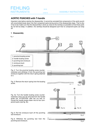
1 Disassembly Fig. 1
2 1 5
4
3
1: proximal locating screw 2: handle locating screw 3: punching tool enclosure 4: enclosure bush 5: punching tool Fig. 2: Turn the proximal locating screw counterclockwise and withdraw it from the punching tool enclosure together with the return spring attached to it.
Fig. 2
Fig. 3: Remove the return spring from the locating screw. Fig. 3
Fig. 4a: Turn the handle locating screw counterclockwise until it can be removed from the handle guide rod. ATTENTION: after the nut was removed the handle breaks down into its four component parts (see fig. 4b).
Fig. 4a
Fig. 4b
Fig. 5: Pull the enclosure bush off the punching tool enclosure.
Fig. 5
Fig. 6: Withdraw the punching tool from the punching tool enclosure.
Fig. 6
2
FEHLING
M 25
INSTRUMENTS
2-05/13
ASSEMBLY INSTRUCTIONS
2 Assembly Figure 7 shows the nine component parts of the totally disassembled aortic punch. The components three (3), four (4) and five (5) all have the same identification number, e.g. 5-002. Only instrument components with the same identification number can be assembled. The other components fit universally to all aortic punches with T-handle. Assembly is done as follows:
2a 2
3
5-002
5-002
5
1: 1a: 2: 2a: 2b: 3: 4:
proximal locating screw return spring handle locating screw handle bushing handle guide rod punching tool enclosure enclosure bushing
5:
punching tool
1a
4
5-002
1
2b 2a
Fig. 7
Following are the steps for assembly: Fig. 8: Slide the punching tool into the punching tool enclosure.
Fig. 8
Fig. 9: Slide the enclosure bush on the punching tool enclosure.
Fig. 9
The holes in the enclosure bush, the punching tool enclosure and the punching tool (see fig. 10a) must lie on top of each other so that there is a through passage for the handle guide rod (see fig. 10b).
Fig. 10a
Abb. 10b
Fig. 11: Slide one of the handle bushes over the handle guide rod, and slide the handle guide rod through the passage described above. Make sure that the wavy edge of the bush is oriented towards the enclosure bush (see fig. 11a). Fig. 11a
Fig. 11
3
FEHLING
M 25
INSTRUMENTS
2-05/13
ASSEMBLY INSTRUCTIONS
Fig. 12: Put the second handle bush on the projecting end of the handle guide rod so that the wavy edge is oriented towards the enclosure bush. Place the handle nut on the thread at the end of the handle guide rod and turn it clockwise to tighten.
Fig. 12
Fig. 13: Slide the return spring on the proximal locating screw up to the stop. Fig. 13
Fig. 14: Slide the return spring into the punching tool enclosure. Fig. 14
Fig. 15: Place the proximal locating screw on the internal thread of the enclosure and turn it clockwise to tighten. Fig. 15
Finally check that the aortic punch can be moved as intended. If this is the case, the assembly is terminated. Before sterilizing please moisten the hinge parts and the slide faces with an approved and appropriate instrument oil to ensure easy movement of the aortic punch.
FEHLING Hanauer Landstr. 7A · 63791 Karlstein/Germany · www.fehling-instruments.de
INSTRUMENTS +49 (0) 61 88 – 95 74.40 · +49 (0) 61 88 – 95 74.45 · [email protected]