FEHLING INSTRUMENTS
CERAMO TRADITION X Punches Assembly Instructions
3 Pages
Preview
Page 1
1
FEHLING
M10
INSTRUMENTS
2-01/14
ASSEMBLY INSTRUCTIONS
CERAMO® TRADITION X Punches 1
3
Disassembly
4
2
1
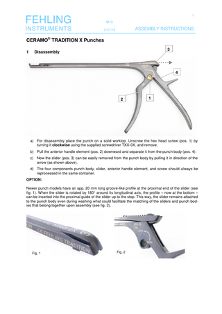
a) For disassembly place the punch on a solid worktop. Unscrew the hex head screw (pos. 1) by turning it clockwise using the supplied screwdriver TXX-0X, and remove. b) Pull the anterior handle element (pos. 2) downward and separate it from the punch body (pos. 4). c) Now the slider (pos. 3) can be easily removed from the punch body by pulling it in direction of the arrow (as shown above). d) The four components punch body, slider, anterior handle element, and screw should always be reprocessed in the same container. OPTION: Newer punch models have an app. 20 mm long groove-like profile at the proximal end of the slider (see fig. 1). When the slider is rotated by 180° around its longitudinal axis, the profile – now at the bottom – can be inserted into the proximal guide of the slider up to the stop. This way, the slider remains attached to the punch body even during washing what could facilitate the matching of the sliders and punch bodies that belong together upon assembly (see fig. 2).
Fig. 1
Fig. 2
2
FEHLING
M10
INSTRUMENTS
2-01/14
2
ASSEMBLY INSTRUCTIONS
Assembly (with the aid of the fitting device TXW-6X)
6 5
Only components belonging to the same unit may be assembled, with the exception of the screw which fits all punches. Component compatibility can be verified by means of the identification number (pos. 5) that is marked on all components (except the screw). NOTE: Before assembling the contact areas (pos. 6) have to be lubricated.
7
8
9
10
a) Before placing the punch in the fitting device the slider has to be attached to the punch body. For doing so place the front guide of the slider (pos. 7) on the guiding rail (pos. 8) of the punch body, and the slider with the spring (pos. 9) on the milled groove (pos. 10) in the punch body at the same time. b) Push slider slightly in direction of the punch foot and hold it. Place the two parts held in this position on the fitting device.
3
FEHLING
M10
INSTRUMENTS
2-01/14
ASSEMBLY INSTRUCTIONS
11
c) Slowly push the handle element completely into the matching recess (pos. 11) in the punch body so that the handle element is flush with the punch body. ATTENTION: While pushing the handle element should be moved plane on the fitting device and not be lifted to avoid that it gets jammed. d) Screw the hex head screw counterclockwise into the provided screw hole using the supplied screwdriver TXX-0X. Tighten the screw. ATTENTION: Do not over-tighten. e) The punch is ready for use after a functional test.
3 Warning Please observe the following to avoid damage to the hexagon socket screws: The screws ( TXX-2X) have a left-handed thread. So please absolutely observe the direction of rotation when screwing the screws in and out. Do not use force when screwing the screws in and out. This is absolutely not necessary. Turning the screws by force damages the hexagon socket profile. Please replace the screw or the screwdriver or have it replaced by the manufacturer immediately, when damage to the hexagon socket profile or the screwdriver profile are visible. The screwdriver TXX-0X and the fitting device TXW-6X can be cleaned using cold water and a mild cleaner. They are not suitable for cleaning in hot water and vapor sterilization at 134°C. Sterilizable screwdrivers for use in the operation theatre are available upon request.
FEHLING Hanauer Landstr. 7A · 63791 Karlstein/Germany · www.fehling-instruments.de
INSTRUMENTS +49 (0) 61 88 – 95 74.40 · +49 (0) 61 88 – 95 74.45 · [email protected]