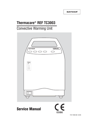
Service Manual
32 Pages
Preview
Page 1
Before you begin . . . Important
Symbols used within this manual: Attention: consult accompanying documents
• Refer to the TC3003 Convective Warming System Operating Manual for detailed operating instructions. Read and understand the Operating Manual and all precautions prior to using the Convective Warming System.
Dangerous voltage
• Review the SAFETY PRECAUTIONS (see page 2) prior to servicing the Convective Warming Unit (Power Unit).
Protective earth (ground)
• For technical assistance, contact your local dealer. Type BF applied equipment NOTE: Extremely high storage temperatures (such as those found in rail cars or automobile trunks on hot summer days) can cause the thermostats within this device to actuate. Should this occur, the REMOVE FROM USE indicator will light when the Power Unit is turned on. If this happens, the thermostats must be manually reset. Refer to section 7, Functional Check and Safety Inspection.
Off-on switch
Fan only (no heat)
32°C
38°C
43°C
46°C
REMOVE FROM USE (indicator light, amber color)
Do not use in operating room (OR) or Intensive Care Unit (ICU)
© 2000. Gaymar Industries, Inc. All rights reserved. Gaymar and Thermacare trademarks are registered in U. S. Patent and Trademark Office. www.gaymar.com
16°C - 29°C
Ambient operating temperature
Table of Contents
Contents Section 1.0 2.0 3.0 4.0 5.0 6.0 7.0 8.0 9.0 10.0 11.0 12.0 13.0
Introduction Page Safety Precautions ... 2 Repair Policy / Return Authorization ... 3 Specifications ... 4 Theory of Operation ... 5 Controls and Indicators ... 7 Preventive Maintenance ... 7 Functional Check and Safety Inspection ... 8 Inspection Form ... 16 Troubleshooting ... 19 Repair Procedures ... 21 Drawings/Parts List ... 24 TC20 Test Tool Schematic ... 27 Wiring Diagram ... 28
Illustrations Figure 1 2A/B 3 4 5 6 7 8 9 10 11 11a 12 13
Description Page Convective Warming System ... 5 Power Unit Mounting ... 5 Pole Mounting Height Limit ... 5 Operator Control Panel ... 6 TC20 Test Tool ... 9 Temperature Sensor Location ... 10 Troubleshooting Chart - NO HEAT ... 19 Troubleshooting Chart - NO AIR FLOW... 20 Drawing/Parts List ... 24 Drawing/Parts List ... 25 Drawing/Parts List ... 26 Power Cord Plugs ... 27 TC20 Test Tool Schematic ... 27 Wiring Diagram ... 28
Tables Table 1 2
Description Page Air Temperatures ... 4 Functional Check/Inspection Form ... 16
1
Section 1 - Safety Precautions
1.0
Safety Precautions
Review the following SAFETY PRECAUTIONS prior to testing the Power Unit.
DANGER • Explosive hazard. Do not use in the presence of flammable anesthetics. • Risk of electric shock. Disconnect power before servicing the TC3003 Power Unit.
WARNING This device generates heated air flow. Excessive heat could cause thermal stress or skin lesions. Failure to follow these precautions could result in death or serious injury: • Use this system only under direction of a physician. Read and understand the Operating Manual, Quilt Instructions for Use, and all precautions before using. • Repairs should be performed only by qualified personnel such as certified biomedical electronics technicians or certified clinical engineers familiar with repair practices for servicing medical devices, and in accordance with the Service Manual. Damage to the Power Unit or malfunction could otherwise result. • Always perform the FUNCTIONAL CHECK AND SAFETY INSPECTION after making repairs and before returning the Power Unit to patient use. Document your findings on the INSPECTION FORM. Improper repair may result in death or serious injury, equipment damage, or malfunction. (continued next column)
WARNING • After performing the thermostat test procedure, verify that the TC20 Test Tool or any installed test jumpers have been removed before returning the Power Unit to patient use. Failure to remove the TC20 Test Tool or test jumpers may result in death, serious injury or equipment malfunction. • Always unplug the Power Unit before attaching or removing the TC20 Test Tool or test jumpers and when resetting thermostats. Failure to unplug the Power Unit could result in electrical shock and cause death or serious injury. • Use only Gaymar replacement parts as identified in the parts lists (pp. 24-27). Use of substitute parts could lead to power unit malfunction or patient injury. • The Temperature Control PC Board is pre-set at the factory. Do not attempt to calibrate it. Adjustment of the Control PC Board in the field could result in patient injury. • Use care when resetting the thermostats. Excessive force (force greater than 5 pounds) can damage the overtemp protection device and/or inadvertently alter the trip temperature of the device.
CAUTION • U. S. Federal law restricts this device to sale by or on the order of a physician. • For grounding reliability, plug only into a properly grounded outlet. • The HEPA filter must be installed correctly. Failure to install the filter correctly will prevent it from functioning properly and could allow unfiltered air to reach the patient. • When using an I. V. pole, do not mount the Power Unit higher than 1 meter. Otherwise, the Power Unit could tip over.
2
Section 2 - Repair Policy
2.0
Repair Policy
For customers who repair Gaymar Power Units at their location, this manual contains information to allow a qualified biomedical technician to make necessary repairs.
2.1
2.4
Return Authorization
Please contact your local dealer.
Limited Warranty
The Thermacare TC3003 Power Unit is warranted free of defects in material and workmanship under normal use and operation for a period of two years, under the terms and conditions of the Gaymar warranty in place at time of purchase. During the warranty period, Gaymar will repair or replace at its sole option, free of charge, any defective parts or products returned with prior authorization prepaid to Gaymar Industries. Consumable items such as filters are excluded. The full warranty is available from Gaymar upon request. Warranty does not cover products abused, misused, or altered outside the factory. There are no obligations on the part of Gaymar for consequential damages arising out of or in connection with the use or performance of the product. Gaymar disclaims all implied warranties including, but not limited to, the implied warranties of merchantability and of fitness for a particular purpose.
2.2
In-Warranty Repairs
All in-warranty field repairs must be authorized by Gaymar's Export Department before proceeding.
2.3
Out-of-Warranty Repairs
If the Power Unit becomes inoperative and the cause cannot be determined, the complete Power Unit may be returned to the factory for servicing at the purchaser's expense. Please contact Gaymar's Export Department to obtain a returned goods (“RG”) number prior to returning equipment.
3
Section 3 - Specifications
3.0
Specifications
3.3
3.1
Physical
The air temperatures are identified on the operator control panel and indicate the average air temperature at the hose end using a Quilt.
Dimensions Weight Enclosure Filter
3.2
42 cm x 28 cm x 27 cm 6.8 kg Thermoplastic HEPA filtration down to 0.2 micron particle size
Electrical
Classification
Type BF, Class 1, grounded equipment suitable for continuous operation. Not classified for protection against harmful ingress of liquid. Input 220-240 V (± 10%), 50 Hz, 7 amps max Motor 1/25 HP, single phase Heater 1200W heating element Detachable Use only an International Cord (Harmonized) three wire cordset using cordage approved to HD-21. Conductor size is 1.0 mm2 (H05VVF3G1.00) Circuit Breaker 10 amp Current Leakage (Earth) 100 microamps max. (90 microamps typical) Ground Resistance 0.15 ohms nominal; 0.5 ohms maximum Ambient Operating Temperature 16°C to 29°C Temperature Setting
Temperature Fan only
32°C
NOTE: The air temperature around the patient is affected both by the ambient room temperature and the use of an insulating blanket on top of the Quilt.
3.4
43°C
46°C
Table 1 - Air Temperatures 4
Safety System
Dual Patient Safety Temperature Limit Thermostats Either of two independently operating thermostats will shut off the TC3003 at a preset high limit temperature. The heater element and blower will remain off until the thermostat is manually reset. HeaterOvertemp Heater overtemp thermostat will shut off the TC3003 in the event of a blower failure or lack of air movement. The heater element and blower will remain off until the thermostat is manually reset. High Temp Indicator The REMOVE FROM USE indicator will light on the front panel when a patient safety thermostat or heater overtemp thermostat has tripped. Also, the heating element and blower will turn off. HEPA Filter Interlock Switch The REMOVE FROM USE indicator will light on the front panel when the HEPA filter has been installed incorrectly or is missing. Also, the heating element and blower will turn off.
3.5 38°C
Temperature Settings
Quilts
All Quilts are made of a nonwoven layer bonded to a plastic film. Quilt material meets U. S. flammability standards: • NFPA 702 “Normal Flammability” • CPSC Part 1632 • California Title 19, Subchapter 7 Clear drape material meets NFPA 702 “Normal Flammability.”
Section 4 - Theory of Operation
4.0
Theory of Operation
4.1
Convective Warming System
IV Pole Clamp
The Convective Warming System (fig. 1) provides a continuous means of warming patients to help prevent and/or treat hypothermia. The system consists of a Convective Warming Unit (Power Unit) and a disposable Quilt. A connecting hose conducts heated air from the Power Unit to the Quilt.
Figure 2A - I. V. Pole or Stand mounted
Figure 1 - Convective Warming System
4.2
Bedrail Hook
TC3003 Power Unit
The TC3003 Power Unit provides a continuous source of air to the Quilt. The Power Unit consists of a HEPA filter, blower, heater, and temperature controller. The Power Unit is a hand-carried portable device which has dual mounting provisions. It can hang on a bedrail or footboard using the bedrail hooks on the back of the unit (see fig. 2B). It can also mount to an I. V. pole or optional accessory stand using the I. V. pole clamp (see fig. 2A). Output air temperatures may be set to one of five temperature settings: fan only, 32°C, 38°C, 43°C, or 46°C.
Figure 2B - Bed rail mounted
CAUTION When using an I. V. pole, do not mount the Power Unit higher than 1 meter (see fig. 3). Otherwise, the Power Unit could tip over. 1 meter maximum
Figure 3 - Pole mounting height limit 5
Section 4 - Theory of Operation (cont’d)
32°C
38°C
43°C
46°C
Figure 4 - Operator Control Panel
Ambient air is drawn in through air vents in the bottom of the enclosure. Air passes through a HEPA filter and across a 1200 watt, open coil heater located in the inlet of a blower. Output air temperature is monitored by a thermistor located directly in the output air stream (plenum) and provides feedback to the solid-state controller. The controller compares the output air temperature to the selected temperature and, using an on-off control scheme, turns the heater on or off accordingly. The maximum output air temperature is limited not only by the control system but by two redundant bimetallic latching thermostats. These thermostats are located in the output air stream and will interrupt power to both the heater and the blower, and light the REMOVE FROM USE indicator on the front panel should the output air temperature exceed predetermined limits. A similar thermostat located directly above the heater is used to protect the internal components in the event of a motor failure. It too will interrupt power to the heater and blower and light the REMOVE FROM USE indicator. Air is delivered to the Quilt using a permanently attached, flexible hose. The hose has a sleeve which is stain resistant and easy to clean.
6
4.3
Quilts
The Quilts distribute air evenly over the covered areas of the patient through openings in the patient side of the Quilt. Quilts consist of layers of plastic and nonwoven material bonded together. Refer to the instructions enclosed with each Quilt.
Section 5 - Controls and Indicators Section 6 - Preventive Maintenance 5.0
Controls and Indicators
5.1
Power
An on/off circuit breaker is located on the front of the unit in the bottom left corner. It controls power to the entire unit. When switched to the ON position, a power indicator in the switch will light.
5.2
Control Panel
An operator control panel (fig. 4, p. 6) is mounted at the top of the Power Unit: • [Power Up] When the power unit is turned on, the system defaults to the 32°C temperature setting. A green light directly above the selector switch will glow indicating the selected temperature range.
6.0
Preventive Maintenance
6.1
HEPA Filter
Dirt that has accumulated on the internal HEPA air filter will reduce the efficiency of the blower and heater. Under normal use, replace the HEPA filter every 1000 operating hours or 12 months, whichever occurs first. Replace the filter only with the Gaymar P/N listed (see parts list, fig. 9, p.24).
WARNING Use only Gaymar replacement parts as identified in the parts lists (pp. 24-27). Use of substitute parts could result in power unit malfunction or patient injury.
• [Temperature Settings] Temperature settings are selected by pressing the appropriate pushbutton -- fan only, 32°C, 38°C, 43°C, or 46°C.
Refer to Functional Check, 7.6 Filter Switch Test & Filter Replacement (p. 14) for instructions.
• [Power Interruption] If electrical power is interrupted momentarily, the existing temperature setting will remain. If electrical power remains off, the TC3003 will default to the 32°C setting when power is restored.
6.2
A REMOVE FROM USE indicator will light:
Blower
The blower motor and fan do not require lubrication.
6.3
Enclosure Exterior
• if a patient safety thermostat or heater thermostat has tripped.
Clean the control panel and Power Unit exterior with a soft cloth lightly dampened with a nonstaining hospital disinfectant.
• if the HEPA filter has been installed incorrectly or is missing.
6.4
The heating element and blower will automatically turn off when these conditions occur.
Quilts
Quilts are not sterile. Quilts are intended for single patient use only. Quilts should be discarded after use. Small rips or tears in quilt material may be temporarily fixed with adhesive tape.
6.5
Hose
Clean the hose with a soft cloth lightly dampened with a nonstaining hospital disinfectant. Place the connector hose under the bed rail hooks when not in use.
6.6
Air Vents
Clean accumulated dirt from the air vents with a vacuum cleaner. 7
Section 7 - Functional Check and Safety Inspection
7.0 Functional Check and Safety Inspection To assure optimum performance, dependability and safety, perform FUNCTIONAL CHECK AND SAFETY INSPECTION as follows:
• Adhesive Tape • TC20 Test Tool*, or two 16 gauge insulated Test Jumpers * The TC20 Test Tool is available from Gaymar. This tool was designed to allow for more convenient testing of the thermostats and eliminate the need to install jumpers. Contact Gaymar's Technical Service Department for more information.
• After repair, and every 12 months thereafter - the FUNCTIONAL CHECK AND SAFETY INSPECTION consists of all procedures (sections 7.1 through 7.9). If your facility's procedures call for more frequent functional test and safety inspections, note this fact on the INSPECTION FORM.
Procedures
An INSPECTION FORM (table 2, pp. 16-18) is provided at the end of this section to facilitate and document the inspection process.
Perform the following procedures carefully, paying particular attention to test setups. Any deviation from the setups, procedures, or test equipment may result in incorrect or misleading results.
Test Equipment
7.1
The following test equipment (or equivalent) is required in order to perform the preventive maintenance procedures:
Examine the overall condition of the Power Unit exterior: 1.
Unplug the power unit.
• Digital air thermistor thermometer (YSI 400 series)
2.
Examine the enclosure, checking for cracks.
3.
Check that exterior screws are tight.
Range: 10°C to 71°C System accuracy: ± 0.6°C
4.
Check that labelling and markings are legible.
5.
Clean accumulated dirt from the air vents with a vacuum cleaner.
NOTE:
6.
1. Include the accuracy of the measuring equipment when making judgments about observed temperature readings. 2. Test Conditions: 230 VAC ± 2 , 21°C-24°C ambient (with heater on); this may require the use of a variable transformer.
Check hose assembly for holes and broken fittings. Replace if necessary.
7.2
Inspection Form
• Temperature sensor (P/N 77948-000)
• #2 Phillips screwdriver • Current Leakage / Ground Resistance Tester • Model TC1050CE, TC2050CE, TC2052CE, or TC2054CE Quilt • Stopwatch 8
• INSPECTION FORM (table 2, pp. 16-18)
Enclosure
Plug, Line Cord
Examine the plug and line cord: 1.
Examine the attachment plug on the line cord to be sure it is in good condition.
2.
Examine the line cord along its entire length for physical damage, such as cuts or cracked insulation. Replace, rather than repair, damaged line cords.
Section 7 - Functional Check and Safety Inspection (cont’d)
7.3
Power Switch
Check the power switch light: 1.
Plug in the Power Unit. Turn the power switch on.
2.
Verify that the power switch is lit.
3.
Verify the Power Unit starts in the 32°C heat setting.
7.5.1 TC20 Test Tool Procedure (steps 1 to 20) [see fig. 10, p. 25, for TC20 Test Tool part number] 1.
Unplug the Power Unit. WARNING
Always unplug the Power Unit before attaching or removing the TC20 Test Tool and when resetting thermostats. Failure to unplug the Power Unit could result in electrical shock and cause death or serious injury.
7.4 Temperature Settings Switches Examine the overall condition of the control panel: 1.
Select each of the five temperature settings. Verify that the appropriate indicator for each lights.
7.5 Thermostat and REMOVE FROM USE Alert Test the Patient Limit Thermostats and REMOVE FROM USE Alert. The following procedure describes two different approaches for measuring the trip points (actuation temperatures) of the Power Unit's patient limit thermostats. There are two patient limit thermostats (item 18, fig. 11, p. 26) within the Power Unit and each must be tested. The TC20 Test Tool helps simplify these tests. Steps 1 to 20 (pp. 9-11) should be followed when a TC20 Test Tool is available. For those facilities not having access to a TC20, follow steps 21 to 50 (pp. 12-13). NOTE: A third thermostat, the heater overtemp thermostat (item 33, fig. 11, p. 26), is provided to protect internal components in the event of a motor blockage or failure. It does not need to be function tested.
2.
Remove the six screws on the back of the unit. Carefully separate the two halves of the enclosure.
3.
Connect the TC20 Test Tool (fig. 5) to the 5-pin field test connector on back of the PC board and route the TC20 Test Tool cable out through the opening in the bottom of the unit (see fig. 10, p. 25). Close the two halves of the enclosure and temporarily secure it closed with adhesive (duct) tape. Plug in the power unit.
S2
S3
THERMOSTAT BYPASS OVERTEMP
HEAT
Figure 5 - TC20 Test Tool (for schematic, see figure 12, p. 27)
9
Section 7 - Functional Check and Safety Inspection (cont’d)
Figure 6A - Hose detail, showing sensor location
Figure 6B - Test setup
Figure 6 - Temperature sensor location 4.
Set the two TC20 Test Tool toggle switches as follows: • THERMOSTAT BYPASS -- place in center position; • HEAT/OVERTEMP -- place in HEAT position.
5.
Locate the air temperature sensor at the center of the end of the hose (fig. 6A). Secure the sensor with adhesive tape. Verify that the sensor is located at the center of the hose.
6.
Connect the hose to a Model TC1050CE, TC2050CE, TC2052CE, or TC2054CE Quilt (fig. 6B).
7.
Turn the Power Unit on. Select the 46°C setting.
8.
Run the Power Unit for 5 to 10 minutes at the 46°C setting. The temperature will oscillate. During this time interval, familiarize yourself with the following steps 9 through 14. Have a stopwatch ready.
9.
Place the HEAT/OVERTEMP switch to OVERTEMP. The temperature should start to increase. When the air temperature reaches 48°C, start the stopwatch.
10. Allow the Power Unit to heat until either the S2 or S3 Test Tool thermostat indicator is lit. Stop the stopwatch and note the highest temperature displayed. This is the upper limit temperature for one of the thermostats. Record the time and temperature on the INSPECTION FORM. 10
Verify that the REMOVE FROM USE light is lit. NOTE: It is acceptable if both thermostats trip simultaneously, in which case the S2 and S3 indicators will both be off. If this occurs, record the elapsed time and temperature. Verify that the REMOVE FROM USE indicator is lit. Verify that both the S2 and S3 indicators light by toggling the THERMOSTAT BYPASS switch from the S2 to S3 position. (If both thermostats have tripped, skip steps 11-14 and proceed to step 15.) 11. Switch the TC20 THERMOSTAT BYPASS to whichever thermostat (S2 or S3) is lit. This will short out the thermostat which opened first so that the second thermostat can be tested. Switch the TC20 from OVERTEMP to HEAT to allow the Power Unit to return to normal operating temperature before testing the second thermostat. 12. Run the Power Unit again for 5 to 10 minutes in the 46°C setting. The temperature will oscillate. Have a stopwatch ready. 13. Place the OVERTEMP/HEAT switch to OVERTEMP. The temperature should start to increase. When the air temperature reaches 48°C, start the stopwatch. 14. Continue to monitor the TC20 Test Tool until the second thermostat indicator is lit. Stop the stopwatch and note the highest temperature displayed. This is the upper limit temperature
Section 7 - Functional Check and Safety Inspection (cont’d) for the other thermostat. Record the time and temperature on the INSPECTION FORM (table 2, pp. 16-17). Plot these values on table 2, p. 18.
c.
Bypass S2 by placing the THERMOSTAT BYPASS switch in the S2 position. Place the HEAT/ OVERTEMP Switch to OVERTEMP. Allow the Power Unit to operate. When the air temperature reaches 48°C, start the stopwatch.
d.
Allow the Power Unit to heat until the S3 thermostat indicator is lit. Stop the stopwatch and note the highest temperature displayed. This is the upper limit temperature for the S3 thermostat. Record the elapsed time and temperature.
e.
Verify that the REMOVE FROM USE light is lit.
f.
The S3 thermostat must trip within the acceptance window (see table 2, p. 18). If this condition is not met, do not put the Power Unit in service. Call Gaymar's Technical Service Department for assistance (see inside front cover for telephone numbers).
g.
Unplug the Power Unit.
h.
Open the enclosure and allow the Power Unit to cool for 5-10 minutes.
i.
Remove the filter retainer and nut. Remove the filter. Remove the jumper from the S4 thermostat. Press the S4 reset button and insure it is reset. Replace the filter, filter retainer, and nut.
j.
Reset both the S3 and S2 thermostats by pressing their center reset buttons. (The S2 thermostat may have retripped.)
Verify that the REMOVE FROM USE light is lit. 15. Thermostat trip acceptance Both thermostats must trip within the acceptance window (see table 2, p. 18). If this condition is not met, do not put the Power Unit in service. Call Gaymar's Technical Service Department for assistance (see inside front cover for telephone numbers). 16. Unplug the power unit. Open the enclosure to allow the Power Unit to cool for 5-10 minutes. 17. Locate the two patient limit thermostats (item 18, fig. 11, p. 26). Reset S2 by gently pressing the center reset button. WARNING
Use care when resetting the thermostats. Excessive force (force greater than 5 pounds) can damage the overtemp protection device and/ or inadvertently alter the trip temperature of the device.
NOTE: Use care when resetting the thermostats since the power terminals are delicate. Avoid flexing the terminals. Thermostats with loose terminals should be replaced and retested. 18. Press the center reset button of S3. Verify it has reset (indicated by an audible "click" and tactile feedback). If it "clicks", proceed to step 19. If you don't hear a "click", then what was assumed to be the patient limit thermostat S3 tripping was actually the heater overtemp thermostat S4 in the same circuit. This will rarely occur. If it has occurred, proceed as follows: a.
Remove the filter retainer and nut. Remove the filter. Jumper out the S4 thermostat. Replace the filter, filter retainer and nut.
b.
Run the Power Unit for 5 to 10 minutes in the 46°C setting.
19. Remove the TC20 Test Tool. WARNING ARNING
After performing the preceding test procedure, verify that the TC20 Test Tool and all jumpers have been removed before returning the Power Unit to patient use. Failure to do so may result in death, serious injury, or equipment malfunction. 20. Proceed to the FILTER SWITCH TEST (section 7.6, p. 14).
11
Section 7 - Functional Check and Safety Inspection (cont’d)
7.5.2 ALTERNATE Test Jumper Procedure (steps 21 to 50)
26. Unplug the Power Unit. Carefully separate the enclosure slightly.
21. Unplug the Power Unit.
27. Unplug the thermistor (item 13, fig. 10, p. 25) from the back of the control board. NOTE: The power resistor on the back side of the PC board may be hot to touch.
WARNING
Always unplug the Power Unit before attaching or removing jumpers and when resetting thermostats. Failure to unplug the Power Unit could result in electrical shock and cause death or serious injury.
22. There are two patient limit thermostats within the Power Unit and each must be tested. One 16 gauge insulated stranded wire jumper with alligator clips will be required. To help remember to remove the test jumper, label a LARGE, distinctive tag “REMOVE AFTER TEST” and tie the tag to the jumper. Remove the six screws on the back of the unit. Install a jumper across thermostat S3 (item 18, fig. 11, p. 26). Temporarily secure the two halves of the enclosure together with adhesive (duct) tape. 23. Locate the air temperature sensor at the center of the end of the hose (fig. 6A, p. 10). Secure the sensor with adhesive tape. Verify that the sensor is located at the center of the hose. 24. Connect the hose to a Model TC1050CE, TC2050CE, TC2052CE, or TC2054CE Quilt (fig. 6B, p. 10). 25. Plug in the Power Unit and turn it on. Select the 46°C setting. Run the Power Unit for 5 to 10 minutes. The temperature will oscillate. During this time interval, familiarize yourself with the following steps 26 through 31, so that the procedure can be accomplished quickly, without letting the Power Unit cool. NOTE: Perform the following steps 26 through 31 as quickly as possible, to prevent the Power Unit from cooling down: 12
28. Put the enclosure back together and secure it with adhesive (duct) tape. 29. Plug in the Power Unit and turn it on. Leave unit in 32°C temperature setting. Have a stopwatch ready. NOTE: Do not set the TEMPERATURE SETTINGS switch to fan only since this setting disables the heater. 30. The temperature should increase. When the air temperature reaches 48°C, start the stopwatch. The Power Unit will heat until the S2 thermostat trips. When this happens, the blower and heater will shut off. Stop the stopwatch and note the highest temperature displayed. This is the upper limit temperature for thermostat S2. Record the time and temperature on the INSPECTION FORM (table 2, pp. 16-17). 31. Verify that the REMOVE FROM USE light is lit. 32. Unplug the Power Unit. 33. Open the enclosure and allow the Power Unit to cool for 5-10 minutes. 34. Locate the two patient limit thermostats (item 14, fig. 11, p. 26). Gently press the reset button in the center of each thermostat. Move the jumper across thermostat S2. WARNING
Use care when resetting the thermostats. Excessive force (force greater than 5 pounds) can damage the overtemp protection device and/or inadvertently alter the trip temperature of the device.
NOTE: If both thermostats reset, both thermostats have tripped. This is acceptable.
Section 7 - Functional Check and Safety Inspection (cont’d)
NOTE: Use care when resetting the thermostats since the power terminals are delicate. Avoid flexing the terminals. Thermostats with loose terminals should be replaced and retested. Be certain the thermostats have cooled for 5-10 minutes before resetting. NOTE: If thermostat S2 does not reset, the heater overtemp thermostat has tripped. In the unlikely event that this has occurred, perform the following: a) remove the filter retainer and nut; b) remove the filter; c) jumper the S4 heater overtemp thermostat; and d) replace the filter, filter retainer, and nut. Return to step 25. 35. Reconnect the thermistor to the control board. 36. Put the enclosure back together and secure it with tape. 37. Plug in the Power Unit. Turn it on. 38. Run the Power Unit for 5-10 minutes in the 46°C setting to stabilize the system temperature. NOTE: Perform the following steps 39 through 44 as quickly as possible, to prevent the Power Unit from cooling down: 39. Unplug the Power Unit. Carefully separate the enclosure slightly. 40. Unplug the thermistor (item 13, fig. 10, p. 25) from the back of the control board. 41. Put the enclosure back together and secure it with tape. 42. Plug in the Power Unit and turn it on. Leave unit in 32°C temperature setting. Have a stopwatch ready.
and note the highest temperature displayed. This is the upper limit temperature for that thermostat. Record the time and temperature on the INSPECTION FORM (table 2, p. 17). Plot these values on table 2, page 18. 44. Verify that the REMOVE FROM USE light is lit. 45. Unplug the Power Unit. 46. Open the enclosure and allow the Power Unit to cool for 5-10 minutes. 47. Thermostat trip acceptance Both thermostats must trip within the acceptance window (see table 2, p. 18). If this condition is not met, do not put the Power Unit in service. Call Gaymar's Technical Service Department for assistance (see inside front cover). 48. Remove the jumper from the patient limit thermostat. If a jumper was used on the S4 heater overtemp thermostat, remove the filter retainer, nut, and filter. Remove the jumper from S4. Reset S4 (indicated by an audible "click" and tactile feedback). Replace the filter, filter retainer, and nut. WARNING
After performing the preceding test procedure, verify that all test jumpers have been removed before returning the Power Unit to patient use. Failure to remove test jumper(s) may result in death, serious injury, or equipment malfunction.
49. Reconnect the thermistor connector to the back of the control board. (continued)
NOTE: Do not set the TEMPERATURE SETTINGS switch to fan only since this setting disables the heater. 43. The temperature should start to increase. When the air temperature reaches 48°C, start the stopwatch. Allow the Power Unit to heat until thermostat S3 trips. Stop the stopwatch 13
Section 7 - Functional Check and Safety Inspection (cont’d)
50. Reset the thermostats by gently pressing the center reset buttons.
6.
WARNING
Use care when resetting the thermostats. Excessive force (force greater than 5 pounds) can damage the overtemp protection device and/or inadvertently alter the trip temperature of the device.
NOTE: Use care when resetting the thermostats since the power terminals are delicate. Avoid flexing the terminals. Thermostats with loose terminals should be replaced and retested.
7.6 Filter Replacement and Filter Switch Test (every 12 months or 1000 operating hours, whichever occurs first) 1.
Unplug the Power Unit. Separate the two halves of the enclosure. Lay the Power Unit on its back.
2.
Remove the filter retainer and nut. Remove the filter.
3.
Put the enclosure back together and secure it with tape.
4.
Plug in the Power Unit. Turn it on. Verify that the blower does not start and that the REMOVE FROM USE light is lit.
5.
A timer which counts total running hours is located inside the Power Unit for use by service personnel. Timer readings may be used to track HEPA filter usage intervals. To read the hour timer: a.
b. 14
Unplug the Power Unit. Separate the two halves of the enclosure again. Locate the hour timer (see figure 10, p. 25). Plug in the Power Unit and turn it on. Read the hour timer and record the total running hours on the INSPECTION FORM. Turn the Power Unit off.
Unplug the Power Unit. Install filter. (Install new filter every 1000 operating hours or 12 months, whichever occurs first.) Replace the filter only with the Gaymar P/N listed (see parts list, fig. 9, p.24). Record the hour timer reading onto the new filter label. Reattach filter and nut. CAUTION
The HEPA filter must be seated properly. Failure to install the filter correctly will prevent it from functioning properly, and could allow unfiltered air to reach the patient and cause injury.
7.
7.7
Replace the six screws holding the enclosure together.
Quilt Temperature
Verify temperature output at each heat setting: 1.
2.
Prepare the Power Unit test setup, if it has not been previously prepared: a.
Locate the air temperature sensor at the center of the end of the hose (fig. 6A, p. 10). Secure the sensor with adhesive tape. Verify that the sensor is located at the center of the hose.
b.
Connect the hose to a Model TC1050CE, TC2050CE, TC2052CE, or TC2054CE Quilt (fig. 6B, p. 10).
c.
Plug in the Power Unit and turn it on.
Set the TEMPERATURE SETTINGS switch to 32°C. Run the Power Unit for 5 minutes. After 5 minutes, note the two highest and two lowest temperature readings. Record the average of these four temperatures on the INSPECTION FORM (table 2, p. 17). Allowable 32°C temperature: 30.6°C to 33.9°C average
Section 7 - Functional Check and Safety Inspection (cont’d)
3.
4.
Repeat step 2 for 38°C setting. Average temperatures and record.
7.10 Completing the Functional Check and Safety Inspection
Allowable 38°C temperature: 36.1°C to 39.4°C average
If the Power Unit has passed the FUNCTIONAL CHECK AND SAFETY INSPECTION for all requirements of procedures 7.1 through 7.9 , the Power Unit should be considered operational and suitable for return to service.
Repeat step 2 for 43°C setting. Average temperatures and record. Allowable 43°C temperature: 41.7°C to 45.0°C average
5.
Repeat step 2 for 46°C setting. Allowable 46°C temperature: 44.7°C to 47.5°C average
6.
If the temperatures in steps 2 through 5 are not correct, do not put the Power Unit into service. Call your local dealer for assistance.
7.
Unplug the Power Unit.
7.8
This completes the recommended FUNCTIONAL CHECK AND SAFETY INSPECTION for the TC3003 series Power Unit.
Ground Resistance
Check grounding resistance: 1.
Use a current leakage/ground resistance tester to measure the resistance between the grounding pin on the power entry module and the I. V. pole clamp. An unplated area on the underside of the I. V. pole clamp has been provided for this test. Record the value.
2.
The value should be less than 0.5 ohms.
7.9
Current Leakage
Measure current leakage: 1.
Measure and record the maximum earth current leakage (ground open). An unplated area on the underside of the I. V. pole clamp has been provided if needed for this test. Measure at all combinations of: • line polarity • neutral open/closed
2.
The current leakage should not exceed 100 microamperes in any condition.
15
Section 8 - Inspection Form T C3003 Po we r Unit Functio nal Che ck and Safe ty Inspe ctio n Fo rm Location _________________________________________________ Hour timer (total hours) _____________ P rocedure (s)
7.1
Enclosure
7.2
P lug, line cord, strain relief
7.3
Power switch
7.4
TEMP ERATU RE SETTIN GS switches
Replaced HEPA Filter:
Initials _______________
Yes _______
Done? (check)
N o _______
Date _____________________
Serial N umber ______________________
Action
Results ** (circle selection)
1
Unplug Po we r Unit.
2
Check enclosure for cracks.
Pass
Fail
3
Check screws.
Pass
Fail
4
Check labelling and markings.
Pass
Fail
5
Check/clean air vents.
Pass
Fail Fail
6
Check hose assembly.
Pass
1
Examine plug.
Pass
Fail
2
Examine cord. Check strain relief.
Pass
Fail
1
P lug in Power U nit. Check that the circuit breaker lights.
Pass
Fail
3
Verify that Power U nit star ts in 32°C heat setting.
Pass
Fail
1
Check each temperature setting. Verify appropriate indicators light.
Pass
Fail
Pass
Fail
Pass
Fail
Pass
Fail
1
Unplug Po we r Unit. R e mo ve scre ws.
3
Connect TC20 Test Tool. Tape enclosure closed. P lug in Power U nit.
4
TC20 Test Tool settings:
5
P repare test setup. Mount air temperature sensor at the center of the end of the hose. Connect to quilt.
THERMOSTAT BYPASS--place in center position. HEAT/OVERTEMP--place in Heat position.
7
Turn Power U nit on. Select 46°C setting.
8
Run Power U nit for 5-10 minutes at 46°C setting to stabilize.
9
P lace TC20 to OVERTEMP. Star t stopwatch at 48°C.
10 Stop stopwatch when S2/S3 indicator on TC20 lights. N ote time/temperature. Record results. ___________ seconds _________° C Thermostat* and REMOVE FROM 7.5.1 U SE aler t (TC20 TEST TOOL P ROCEDU RE)
Verify that REMOVE FROM U SE indicator lights. 11 Bypass thermostat. Switch TC20 from OVERTEMP to HEAT. 12 Run Power U nit for 5-10 minutes at 46°C setting to stabilize. 13 P lace TC20 to OVERTEMP. Star t stopwatch at 48°C. 14 Stop stopwatch when S2/S3 indicator on TC20 lights. N ote time/temperature. Record results. ___________ seconds __________°C Verify that REMOVE FROM U SE indicator lights. 15 Verify that the time/temperature values in steps 10 and 14 for both thermostats fall within the acceptance window on page 3 of the IN SP ECTION FORM. 16 Turn off Power U nit. Open enclosure. Let Power U nit cool for 5-10 minutes. 17 Reset S2 patient limit thermostat. 18 Reset S3 patient limit thermostat. If a click is heard, proceed to step 19. If click is not heard, per form steps 18a. through 18j. 19 Remove TC20 Test Tool. 20 P roceed to 7.6, FILTER SWITCH TEST.
21 Unplug Po we r Unit. R e mo ve scre ws. Install jumpe r acro ss the rmo stat S3. Tape e nclo sure clo se d. 23 P repare test setup. Mount air temperature sensor at the center of the end of the hose. Connect to quilt. 25 Turn Power U nit on. Select 46°C setting. Run Power U nit for 5-10 minutes at 46°C setting to stabilize. Label jumper "REMOVE AFTER TEST." 26 Unplug Po we r Unit. Se parate the e nclo sure slightly.
7.5.2
Thermostat* and REMOVE FROM U SE aler t (ALTERN ATE TEST JU MP ER P ROCEDU RE) [continued on other side]
27 U nplug the thermistor from the control board. 28 Tape enclosure closed. 29 P lug in and turn on Power U nit. Leave in 32°C setting. 30 Star t stopwatch at 48°C. Stop stopwatch when blower/heater shuts off. N ote time/ temperature. Record results. ___________ seconds __________°C 31 Verify REMOVE FROM U SE indicator lights.
Pass
32 U nplug the Power U nit. 33 Open enclosure. Allow Power U nit to cool for 5-10 minutes. 34 Reset thermostat(s). Move jumper to thermostat S2. 35 Reconnect the thermistor to the control board. 36 Tape enclosure closed. * If both thermostats trip simultaneously (i.e., at the same time and temperature), record the same results in 14 as in 10, and in 43 as in 30. ** Circling "Fail" indicates ser vice or repair is required. Contact your local dealer for assistance.
16
Table 2 - Functional Check / Inspection Form (p. 1)
Fail
Section 8 - Inspection Form (cont’d) T C3003 Po we r Unit Functio nal Che ck and Safe ty Inspe ctio n Fo rm P rocedure(s)
7.5.2
7.6
7.7
7.8
7.9
Thermostat* and REMOVE FROM U SE aler t (ALTERN ATE TEST JU MP ER P ROCEDU RE) [continued from other side]
Done? (check)
Action 37
P lug in Power U nit. Turn unit on.
38
Run the Power U nit for 5-10 minutes in the 46°C setting to stabilize.
39
Unplug Po we r Unit. Se parate the e nclo sure slightly.
40
U nplug the thermistor from the control board.
41
Tape enclosure closed.
42
P lug in and turn on Power U nit. Leave in 32°C setting.
43
Star t stopwatch at 48°C. Stop stopwatch when blower/heater shuts off. N ote time/temperature. Record results. _________ seconds __________°C
44
Verify REMOVE FROM U SE indicator lights.
45
Unplug Po we r Unit.
46
Open enclosure. Allow Power U nit to cool for 5-10 minutes.
47
Verify that the time/temperature values in steps 30 and 43 for both thermostats fall within the acceptance window on page 3 of the IN SP ECTION FORM.
48
R e mo ve the jumpe r( s) fro m the patie nt limit the rmo stat and he ate r o ve rte mp the rmo stat.
49
Reconnect the thermistor to the control board.
50
Reset the thermostats by pressing center reset buttons.
1
Unplug Po we r Unit. Se parate e nclo sure halve s.
2
Remove filter retainer and nut. Remove filter.
Pass
Fail
Pass
Fail
3
Tape the enclosure closed.
4
P lug in Power U nit. Verify the blower does not turn on.
Pass
Fail
Verify the REMOVE FROM U SE indicator lights.
Pass
Fail
Filter replacement and filter switch test 5
Unplug Po we r Unit. Se parate e nclo sure . Plug in Po we r Unit, turn it o n, and re ad ho ur time r. R e co rd to tal running ho urs o n ne w filte r labe l and INSPECT ION FOR M. Turn o ff Po we r Unit.
6
Unplug Po we r Unit. Install ne w filte r if ne ce ssary. R e co rd ho ur time r re ading o nto ne w filte r labe l. R e place filte r re taine r and nut.
7
Close enclosure. Reattach screws.
1
P repare test setup. Mount air temperature sensor at the center of the end of the hose. P lug in Power U nit.
2
Turn on Power U nit. Set HEAT SETTIN GS to 32°C. Run Power U nit for 5 minutes. N ote 2 highest and 2 lowest temperatures. Average the 4 readings. Record value : ___________°C [Average of 32°C values must be between 30.6°C and 33.9°C]
Pass
Fail
3
Repeat step 2 for 38°C setting. Record value: __________°C [Average of 38°C values must be between 36.1°C and 39.4°C.]
Pass
Fail
4
Repeat step 2 for 43°C setting. Record value: __________°C [Average of 43°C values must be between 41.7°C and 45.0°C.]
Pass
Fail
5
Repeat step 2 for 46°C setting. Record value: __________°C [Average of 46°C values must be between 44.7°C and 47.5°C.]
Pass
Fail
7
Unplug the Po we r Unit.
1
Unplug the Po we r Unit. Me asure and re co rd gro und re sistance : _________ o hms [ Gro und re sistance must be le ss than 0.5 o hms.]
Pass
Fail
1
Measure current leakage at the following settings:
Quilt temperature
Ground resistance
Results ** (circle selection)
Current leakage
2
N EU TRAL LIN E
LIN E P OLARITY
Open
N ormal
Open
Reverse
Closed
N ormal
Closed
Reverse
Verify current leakage does not exceed 100 µA for all above conditions.
VALU E
Pass
Fail
* If both thermostats trip simultaneously (i.e., at the same time and temperature), record the same results in 43 as in 30. ** Circling ""Fail"" indicates ser vice or repair is required. Contact Gaymar's Technical Ser vice Depar tment for assistance.
Table 2 - Functional Check / Inspection Form (p. 2)
17
18
Table 2 - Functional Check / Inspection Form (p. 3)
48
50
52
54
56
58
60
62
64
66
68
70
0
10
20
30
40
50
PASS (Safe range)
60
70
90
100
110 Time (Seconds)
80
Fail (Thermostat trip point too low)
120
130
Fail (Thermostat trip point too high)
140
150
160
170
180
190
Section 8 - Inspection Form (cont’d)
Hose output air temperature (°C)
Section 9 - Troubleshooting In addition to the following troubleshooting charts, refer to PREVENTIVE MAINTENANCE (section 6, p. 7) and REPAIR PROCEDURES (section 10, pp. 21-23).
WARNING Always perform the FUNCTIONAL CHECK AND SAFETY INSPECTION after making repairs and before returning the Power Unit to patient use. Failure to perform the FUNCTIONAL CHECK AND SAFETY INSPECTION could result in patient injury.
SYMPTOM:
NO HEAT
NO
DOES QUILT INFLATE?
GO TO NO AIR FLOW SYMPTOM
YES
PRESS EACH SETTING BUTTON. DOES CORRESPONDING LED LIGHT?
NO
CALL TECHNICAL SERVICE
YES
UNPLUG UNIT; MEASURE HEATER RESISTANCE
IS HEATER RESISTANCE BETWEEN 36.4 AND 40.2 OHMS?
NO REPLACE HEATER
YES
UNPLUG RT1 THERMISTOR ASSY. TURN POWER ON. DOES UNIT HEAT?
NO
SUSPECT PC BOARD; CONTACT TECHNICAL SERVICE
YES
REPLACE RT1 THERMISTOR ASSY
Figure 7 - Troubleshooting Chart - NO HEAT
19