GE Healthcare
CARESCAPE B450 Service Manual 2nd edition sw ver 3 Ver MBA313 Dec 2018
Service Manual
260 Pages
Preview
Page 1
CARESCAPE B450 Service Manual Software version 3 Version MBA313
CARESCAPE B450 English 2nd edition 2109358-003 © 2018 General Electric Company. All rights reserved.
Due to continuing product innovation, specifications in this manual are subject to change without notice. For technical documentation purposes, the abbreviation GE is used for the legal entity names, GE Medical Systems Information Technologies, Inc. and GE Healthcare Finland Oy.
2
CARESCAPE B450
2109358-003 2018-12-20
Contents 1
About this manual ...13 Intended use of this manual... 13 Intended audience of this manual ... 13 Manual conventions ... 13 Monitor naming conventions ... 14 Acquisition module naming conventions ... 14 Other naming conventions ... 14 Illustrations and names ... 14 Related documents... 15 Product availability ... 15 Trademarks ... 15 Third party trademarks ... 15 Manufacturer responsibility ... 15
2
Safety ...17 Safety message signal words... 17 Safety symbols ... 17 System safety... 18
3
System overview...19 Short description of the equipment ... 19 Software ... 20 Displays... 21 B450 system components... 21 CARESCAPE ONE... 23 CARESCAPE Dock F0 side views... 23 Acquisition modules... 24 PDM front view ... 24 Modules and parameters ... 24 CARESCAPE Network... 27 Other system components ... 27 Access to external applications ... 28 Controls and connectors ... 29
2109358-003
CARESCAPE B450
3
B450 front panel... 29 B450 side views ... 30 B450 back panel... 30 B450 rear unit connectors ... 31 IEC 60601-1 ... 32 IEC 60601-1-2... 32 IEC 60529... 33 Equipment markings... 33 User interface indicators ... 39 Service requirements... 44 Unique Device Identifier (UDI) ... 45 Product security ... 45 Access control ... 45 Authentication ... 46 Audit ... 46 Personal information security ... 47 Network traffic protection ... 47 Wireless network security... 47 Malicious software protection ... 48 4
Using the service applications ...49 Using the service applications ... 49 Service interface ... 49 Service calibrations... 49 InSite RSvP ... 49 User accounts and passwords for service applications... 50 Accessing the service interface locally from the monitor ... 50 Accessing the service interface with a service PC... 51 Checking the network settings of the target monitor... 51 Configuring the network settings of the service PC... 51 Supported web browsers in service PC ... 51 Secure access with service PC ... 51 Accessing the service interface locally with a service PC ... 52 Accessing the service interface over IX network with a service PC ... 53
4
CARESCAPE B450
2109358-003
Accessing service calibrations ... 54 5
Pre-installation requirements...55 Unpacking ... 55 Pre-installation checklist... 55 System compatibility ... 55 Checking the configuration of the wired CARESCAPE Network infrastructure ... 56 About the monitor's MAC addresses ... 57 Checking the configuration of the wireless MC Network infrastructure ... 57 CARESCAPE ONE installation ... 57 Mounting solutions ... 58 Unity Network Interface Device (ID) ... 58 Power and environmental requirements... 58 Power requirements... 58 Environmental requirements... 58 Electromagnetic compatibility safety precautions ... 59
6
Hardware installation ...61 Hardware installation ... 61 Installing batteries ... 61 Inserting and removing the B450 monitor battery ... 62 Installing the PDM battery ... 62 Installing and mounting the monitor ... 63 Connecting a secondary display... 64 Connecting CARESCAPE Dock F0 to an ePort connector... 65 Connecting CARESCAPE Dock F0 with a 1.5- or 4.5-meter cable... 65 Connecting CARESCAPE Dock F0 with a 30-meter cable ... 66 Installing acquisition modules... 67 Connecting a PDM to the B450 ... 67 Connecting a PDM to an ePort connector ... 67 Connecting E-modules to the B450 ... 68 Connecting to the mains power... 68 Connecting to the CARESCAPE Network... 70 Connecting a Unity Network ID connectivity device to the monitor ... 70
2109358-003
CARESCAPE B450
5
Connecting USB input devices ... 71 Connecting iCollect and other data acquisition systems ... 71 Connecting a local printer ... 72 Connecting to CARESCAPE RAD ... 72 Connecting a remote-on cable ... 72 7
Configuration ...75 Platform configuration... 75 Adjusting display ... 75 Setting up the displays... 75 Adjusting the display brightness automatically ... 75 Adjusting the display brightness manually... 75 Adjusting the alarm light brightness... 76 Adjusting the secondary display ... 76 Calibrating touchscreen ... 76 Configuring wired CARESCAPE network ... 76 Configuring the hostname... 76 Wired CARESCAPE Network configuration ... 77 Wireless CARESCAPE network configuration... 78 Introduction to WLAN configuration... 79 Configuring WLAN settings manually using WPA-Personal ... 79 Configuring WLAN settings manually using WPA-Enterprise... 81 Configuring WLAN settings by uploading a custom configuration file... 84 Configuring channel selection... 85 WLAN certificate management... 86 Configuring advanced WLAN settings ... 87 Configuring date and time ... 89 Setting unit and bed name... 89 Configuring printers ... 90 Adding a printer... 90 Selecting printout types and print locations... 91 Printing a test page... 91 Deleting a printer... 91 Configuring Citrix ... 91
6
CARESCAPE B450
2109358-003
Configuring MUSE/12SL... 93 Admit settings ... 94 Configuring patient ID prefix ... 94 Barcode parser configuration ... 94 Setting power frequency ... 99 Selecting language and locale ... 99 Configuring modules... 100 Configuring module asset number ... 100 Configuring host asset settings... 101 Configuring host asset number... 101 Configuring serial number ... 101 Password management ... 102 User accounts and passwords ... 102 Changing passwords ... 102 Resetting passwords... 103 Configuring connectivity... 104 Configuring remote alarm device ... 104 Restarting the monitor... 104 Setting up the remote service ... 105 Enabling or disabling the remote service connection ... 105 Configuring remote service ... 105 Settings management ... 105 Settings transfer process... 105 Downloading clinical and platform settings... 107 Activating settings... 108 Resetting to factory settings ... 109 License management ... 111 Activating host licenses ... 111 Software packages ... 111 Uploading license file ... 112 Backup and restore... 113 Taking a backup ... 113 Restoring a backup ... 114 Certificate installation... 115
2109358-003
CARESCAPE B450
7
Installing the certificate and private key ... 115 Viewing the current certificate ... 116 Software management ... 116 Software upload ... 117 Software activation ... 117 Uploading software... 118 Activating the host software ... 119 Activating software to acquisition modules, DC/DC board and CPU carrier board... 120 8
Checkout procedures ...123 About the checkout procedures... 123 Required checkout procedures ... 123 Installation check ... 124 Planned maintenance check... 125 Corrective maintenance check ... 125 Performing visual inspection... 125 Performing electrical safety tests ... 126 Test setup... 126 Verifying power outlets ... 127 Verifying power cords and plugs... 128 Ground integrity check ... 128 Testing earth leakage current ... 129 Testing touch current... 131 Patient leakage current tests ... 133 Completing electrical safety tests ... 137 Performing functional check ... 137 Preparing for the functional check... 137 Checking the startup... 137 Checking displays... 138 Checking the status of connected devices... 138 Testing printing to IX printers ... 139 Testing InSite RSvP connectivity... 139 Testing the USB remote control... 139 Testing the mouse... 140
8
CARESCAPE B450
2109358-003
Testing the keyboard... 140 Testing the barcode reader ... 140 Testing wired MC Network communication ... 141 Testing wireless LAN ... 141 Testing Citrix connection ... 142 Completing the functional check ... 142 9
Battery maintenance ...143 Maintaining the battery ... 143 About the lithium-ion battery ... 143 Improving battery performance... 144 Battery storage recommendations... 144 Testing the battery charge ... 144 Charging a battery inside the monitor... 144 Charging and conditioning a battery using an external battery charger... 144 Checking the battery status with monitor software ... 144 Battery recycling ... 145
10 Theory of operation...147 CARESCAPE B450 System block diagram ... 147 AC/DC Power Supply... 149 DC/DC board ... 149 PUIC controller and software... 149 DC/DC subsystem ... 149 User Interface Controller (UIC) subsystem... 151 CPU assembly... 151 CPU module ... 151 CPU carrier board... 151 Other subsystems ... 155 Display subsystem ... 155 Touchscreen sensor ... 155 E-module board... 155 Alarm light board... 155 Speaker ... 156 Keypad & Buzzer ... 156
2109358-003
CARESCAPE B450
9
Recorder unit ... 156 Battery board ... 156 Module rail unit... 156 11 Troubleshooting...157 Troubleshooting guidelines ... 157 Performing basic troubleshooting... 157 Viewing configuration and device information... 158 Information... 158 Viewing hardware statistics ... 159 Hardware statistics ... 160 Pinging a TCP/IP network device... 162 Viewing WLAN diagnostics... 162 WLAN diagnostics ... 163 Viewing log files... 164 Downloading log files ... 164 Power management LEDs ... 165 Network status LEDs... 167 Checking battery status information ... 167 Messages related to various technical issues... 168 Problems and solutions ... 180 Troubleshooting startup failures ... 180 User interface issues... 183 Troubleshooting incorrect system time ... 184 Troubleshooting license issues... 184 Troubleshooting IX Network issues ... 185 Recorder troubleshooting ... 186 Troubleshooting acquisition platform... 186 Troubleshooting CARESCAPE Network communication ... 189 12 Disassembly and reassembly...193 Disassembly guidelines ... 193 ESD precautions ... 193 Reassembly precautions... 193 Required tools... 194 Preparing for disassembly ... 194
10
CARESCAPE B450
2109358-003
Disassembly procedures ... 195 Replacing the recorder unit (FRU)... 195 Replacing the main fuses (FRU)... 197 Replacing the CPU battery (FRU) ... 198 Replacing the battery door unit (FRU)... 199 Replacing the module rail unit (FRU) ... 200 Detaching the front unit and mid-frame assembly from the rear unit assembly... 203 Detaching the CPU assembly (FRU)... 207 Reloading software and settings... 214 Replacing the AC/DC power supply unit (FRU) ... 215 Replacing the WLAN antennas (FRU) ... 216 Detaching the front unit assembly from the mid-frame assembly ... 218 Replacing LCD display unit (FRU)... 221 Replacing the speaker unit (FRU) ... 223 Detaching the user interface board and buzzer from the front unit assembly... 225 Replacing the alarm light board (FRU) ... 226 Detaching DC/DC and E-module board (FRUs) ... 229 Replacing the battery board (FRU) ... 233 13 Service parts...237 Service parts... 237 Ordering parts ... 237 List of FRUs ... 237 A
Test procedure for wireless MC Network infrastructure ...241 Purpose and scope of the test ... 241 Planning the test ... 241 Overview of the test procedure... 242 Test devices needed ... 242 Test setup ... 243 Configuring central station... 243 Setting up the hardwired monitor... 243 Setting up the wireless monitor... 244 Performing the test ... 245
2109358-003
CARESCAPE B450
11
Summarizing and reporting ... 246 Test Form... 246 B
Networking disclosure ...249 Purpose and scope ... 249 Purpose of the monitor connection to a network ... 249 Technical specifications of physical network interfaces ... 249 Network information flows... 251 Required characteristics and configuration of the network for support of the monitor... 256 Potential risks to safety, effectiveness, or security resulting from failure of IT network to provide the required characteristics ... 256
12
CARESCAPE B450
2109358-003
About this manual
1
Intended use of this manual The list below indicates the compatible products (brands, models and descriptions as applicable) with which this manual is to be used. Supported products are covered by the manuals that were delivered with those products. ●
CARESCAPE B450 MBA313
●
CARESCAPE B450–LI MBA313
●
2069156–001 Bedrail Hook Unit, B450
This manual contains instructions necessary to install, maintain and service the device. It gives an overview of the CARESCAPE B450 patient monitoring system, and contains information needed for system installation. Information for the planned and corrective maintenance of the CARESCAPE B450 main unit is also provided. Use the manual as a guide for installation, maintenance and repairs considered field repairable. Where necessary the manual identifies additional sources of relevant information and technical assistance. See the module’s service manual for the planned and corrective maintenance of the acquisition module. See the supplemental information manual for the technical specifications, default settings and compatibility information, including electromagnetic compatibility. See the user manual for the instructions necessary to operate the device safely in accordance with its function and intended use.
Intended audience of this manual This manual is intended for service representatives and technical personnel who install, maintain, troubleshoot, or repair this device.
Manual conventions This manual uses the following styles to emphasize text or indicate an action. Also note the terminology conventions.
2109358-003
Item
Description
bold
Indicates hardware keys and connectors.
bold italic
Indicates menu options, software keys and messages.
italic
Indicates terms for emphasis.
CARESCAPE B450
13
About this manual
Item
Description
>
Indicates menu options to select consecutively.
select
The word select means choosing and confirming.
acquisition device
A generic term when referring to both the acquisition modules (PDM, E-modules) and the acquisition platform (CARESCAPE ONE).
supplemental information
In this manual, the phrase supplemental information refers to information that appears in the Supplemental Information Manual.
NOTE
Note statements provide application tips or other useful information.
Monitor naming conventions In this manual, the CARESCAPE B450 is referred to as the monitor. It may also be referred to as B450.
Acquisition module naming conventions In this manual, the following naming conventions are used to refer to different modules and module categories: ●
PDM: Patient Data Module
●
E-modules: All modules with the prefix E-.
●
E-COP, E-COPSv
●
E-PiCCO
●
Pressure E-modules: E-PP, E-PT
●
CARESCAPE respiratory modules: E-sCO, E-sCOV, E-sCOVX, E-sCAiO, E-sCAiOV, E-sCAiOVX, E-sCAiOE, E-sCAiOVE
●
E-miniC
●
Specialty E-modules: E-NMT, E-EEGX, E-BIS, E-ENTROPY
●
SpO2 E-modules: E-NSATX, E-MASIMO
Other naming conventions For technical documentation purposes, the abbreviation GE is used for the legal entity names, GE Medical Systems Information Technologies, Inc., and GE Healthcare Finland Oy. In this manual, CARESCAPE Network is used to refer to both the IX Network and MC Network except where they need to be differentiated. Then they are referred to as IX Network and MC Network. In this manual, acquisition platform refers to the CARESCAPE ONE acquisition platform. CS ONE may also be used to refer to the CARESCAPE ONE acquisition platform.
Illustrations and names This manual uses illustrations as examples only. Illustrations in this manual may not necessarily reflect all system settings, features, configurations, or displayed data. Names of persons, institutions, and places and related information are fictitious; any similarity to actual persons, entities, or places is purely coincidental.
14
CARESCAPE B450
2109358-003
About this manual
Related documents ●
CARESCAPE B450 User Manual
●
CARESCAPE B450 Supplemental Information Manual
●
CARESCAPE ONE Service Manual
●
Service manuals for acquisition modules
●
CARESCAPE Network Configuration Guide
●
CARESCAPE Wireless Network Configuration Guide
●
CARESCAPE Modular Monitors Mounting Solutions
●
CARESCAPE RAD Service Manual
●
CARESCAPE Citrix Guide
●
Service documentation for displays
●
Unity Network Interface Device (ID) Service Manual
●
iCollect user’s manual
●
Service documentation for laser printers
Product availability NOTE
Due to continual product innovation, design and specifications for these products are subject to change without notice.
Some of the products mentioned in this manual may not be available in all countries. Please consult your local representative for the availability.
Trademarks GE, GE Monogram, and CARESCAPE are trademarks of General Electric Company. MUSE, Trim Knob, UNITY NETWORK, D-lite, D-fend, and Entropy are trademarks of General Electric Company or one of its subsidiaries.
Third party trademarks Masimo SET is a trademark of Masimo Corporation. Covidien, BISx, and BIS are trademarks of a Medtronic company. PiCCO is a trademark of Pulsion Medical Systems SE. Multi-Link is a trademark of CareFusion Corporation or one of its affiliates. WMM, WPA and WPA2 are trademarks of Wi-Fi Alliance.
Manufacturer responsibility GE is responsible for the effects on safety, reliability, and performance of the equipment only if:
2109358-003
●
Assembly operations, extensions, readjustments, modifications, servicing, or repairs are carried out by authorized service personnel.
●
The electrical installation of the relevant room complies with the requirements of the appropriate regulations.
CARESCAPE B450
15
About this manual
●
The equipment is used in accordance with the instructions for use.
●
The equipment is installed, maintained and serviced in accordance with the instructions provided in the related service manuals.
WARNING
16
SAFETY HAZARD. To avoid risks to personnel and patient, or damage to the equipment, only perform maintenance procedures described in this manual. Unauthorized modifications can lead to safety hazards.
CARESCAPE B450
2109358-003
2
Safety Safety message signal words Safety message signal words designate the severity of a potential hazard. DANGER
Indicates a hazardous situation that, if not avoided, will result in death or serious injury.
WARNING
Indicates a hazardous situation that, if not avoided, could result in death or serious injury.
CAUTION
Indicates a hazardous situation that, if not avoided, could result in minor or moderate injury.
NOTICE
Indicates a hazardous situation not related to personal injury that, if not avoided, could result in property damage.
Safety symbols Symbol
Explanation General warning sign. ISO 7010. This symbol is identified by a yellow background, black triangular band, and a black symbol. In this manual this symbol is used only in connection with those warning statements that the labels on the equipment refer to. Caution. ISO 7000. This symbol is identified by a white background, black triangular band, and a black symbol. Follow instructions for use. ISO 7010. This symbol indicates mandatory action and it is identified by a blue background and a white symbol. Consult operating instructions. / Operating instructions. WARNING - Electric shock hazard. This equipment must be serviced by qualified service personnel only. ISO 7010. This symbol is identified by a yellow background, black triangular band, and a black symbol.
2109358-003
CARESCAPE B450
17
Safety
Symbol
Explanation MR Unsafe. Indicates that the device is not intended for use in an MR environment. This symbol is identified by a white background, red or black circular band, and a black symbol. Electrostatic sensitive device. Connections should not be made to this device unless ESD precautionary procedures are followed. Non-ionizing electromagnetic radiation. Interference may occur in the vicinity of this device. Type BF (IEC 60601-1) protection against electric shock. Isolated (floating) applied part suitable for intentional external and internal application to the patient, excluding direct cardiac application. Type BF (IEC 60601-1) defibrillator-proof protection against electric shock. Isolated (floating) applied part suitable for intentional external and internal application to the patient, excluding direct cardiac application. Type CF (IEC 60601-1) protection against electric shock. Isolated (floating) applied part suitable for intentional external and internal application to the patient, including direct cardiac application. Type CF (IEC 60601-1) defibrillator-proof protection against electric shock. Isolated (floating) applied part suitable for intentional external and internal application to the patient including direct cardiac application. Safety ground. Remove power cord from the mains source by grasping the plug. Do not pull on the cable.
System safety For a complete list of system safety messages that apply to the entire system, refer to the user manual. For safety messages specific to parts of the system or to a certain installation or service task, refer to the relevant sections.
18
CARESCAPE B450
2109358-003
System overview
3
Short description of the equipment
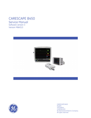
The CARESCAPE B450 is a portable and modular multi-parameter patient monitor for high-acuity applications. The monitor can be used with most patient populations within a professional healthcare facility, but acquisition modules may have limitations for use based on the patient’s age, weight, or clinical condition, or on the type of the care unit (for example, OR or ICU only). There are several types of acquisition modules to choose from based on care requirements and patient needs. The monitor supports a multi-parameter hemodynamic CARESCAPE ONE acquisition platform or a Patient Data Module (PDM). You can extend the monitoring capability to gas measurement, brain monitoring or relaxation measurement by connecting one single-width, E-series module. The optional integrated recorder enables local printing to a thermal paper. The modular system design is inherent in electronics and algorithms: some processing of the measurement signals is done by the acquisition modules and further processing happens on the monitor. The CPU subsystem processes the user input and acquisition data and displays the information on the screen. It controls the monitor operation and communication with the other subsystems and external interfaces. The main software and all platform and clinical settings are stored in a flash memory in the CPU module.
2109358-003
CARESCAPE B450
19
System overview
The monitor has a 12" LCD display with integrated LED backlights and a resistive touchscreen sensor. It also supports one additional display, either a clone or, with a dual video license, an independent secondary display. The touch screen is the main method for user input. The monitor also supports various USB input devices, including a mouse, an alphanumeric keyboard, a barcode reader, and a remote controller. The monitor frame has an integrated handle and GCX mounting. The alarm system includes a speaker for audible alarms and a separate alarm light for visual alarms. The thermal recorder and WLAN options are also available as a field upgrade. The monitor can be mains voltage or battery powered. It has an integrated AC/DC power supply unit and it supports up to two detachable lithium-ion batteries. The DC/DC board provides the supply voltages for the electronics of the device, and takes care of the power path logic and battery management. The monitor is compatible with the wired and wireless MC Network and with the wired IX Network infrastructures. MC (Mission Critical) Network is used for transferring real-time or near real-time patient information between network devices, including numerics, waveforms, alarms, trends and patient information. IX (Exchange) Network provides access for example to MUSE reports, Citrix applications, IX printers, and service tools. For all physical and performance specifications, refer to the supplemental information provided. For more detailed information on the intended use of the device, refer to the user manual.
Software The monitor is highly configurable and provides many monitoring possibilities with a flexible software licensing model. The monitor supports care area specific software packages for OR, PACU, ICU, ED and NICU. Each dedicated software package provides a comprehensive feature set for the different monitoring needs and can be further extended with the optional feature licenses. Software license model supports trial licensing and easy field upgrades with license key activation.
20
CARESCAPE B450
2109358-003