Technical Reference Manual
654 Pages
Preview
Page 1
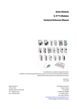
Datex-Ohmeda S/5™ E-Modules Technical Reference Manual
All specifications are subject to change without notice. CAUTION: U.S. Federal law restricts this device to sale by or on the order of a licensed medical practitioner. Outside the USA, check local laws for any restriction that may apply. M1021573 June, 2005
Datex-Ohmeda Inc. P.O. Box 7550 Madison, WI 53707-7550, USA Tel: +1 608 221 1551 Fax: +1 608 222 9147
GE Healthcare Finland Oy Helsinki, Finland P.O. Box 900 FI-00031 GE, FINLAND Tel: +358 10 39411 Fax: +358 9 1463310 www.datex-ohmeda.com www.gehealthcare.com © 2005 Copyright General Electric Company
Responsibility of the manufacturer GE Healthcare Finland Oy (GE) is responsible for the safety, reliability and performance of the equipment only if:
• modifications, service and repairs are carried out by personnel authorized by GE. • the electrical installation of the room complies with appropriate requirements. • the equipment is used in accordance with the User's Guide and serviced and maintained in accordance with the Technical Reference Manual.
Trademarks Datex, Ohmeda, S/5, D-lite, D-lite+, Pedi-lite, Pedi-lite+, Mini D-fend, D-fend, D-fend+, OxyTip+, MemCard, ComWheel, EarSat, FingerSat, FlexSat, PatientO2, Entropy, Patient Spirometry and Tonometrics are trademarks of GE Healthcare Finland Oy. All other product and company names are property of their respective owners. © 2005 General Electric Company. All rights reserved. A portion of the Entropy software is derived from the RSA Data Security, Inc. MD5 Message-Digest Algorithm.
Master table of contents
Datex-Ohmeda E-Modules Technical Reference Manual, Order code: M1021573
Document No.
Updated
Description
M1027822
Compact Airway Modules, E-CAiOVX, E-CAiOV, E-CAiO, E-COVX, E-COV and E-CO
1
M1027824
PRESTN Modules, E-PRESTN, E-RESTN, E-PRETN
2
Patient Side Modules, E-PSM, E-PSMP
3
M1027825
Cardiac Output Modules E-COP and E-COPSv
4
M1027826
Pressure Module, E-P, Pressure Temp Module, E-PT
5
M1027827
Dual Pressure Module, E-PP
6
M1027828
Nellcor Compatible Saturation Module, E-NSAT
7
M1027829
Single-width Airway Module, E-miniC
8
M1027830
Tonometry Module, E-TONO
9
M1027831
Entropy Module, E-ENTROPY
10
M1027832
EEG Module, E-EEG and EEG Headbox, N-EEG
11
M1027833
BIS Module, E-BIS
12
M1027834
NeuroMuscular Transmission Module, E-NMT
13
M1027835
Device Interfacing Solution, N-DISxxx
14
M1027836
Interface Module, E-INT
15
M1027837
Recorder Module, E-REC
16
M1027817
Memory Module, E-MEM
17
Remote Controllers, K-REMCO, K-CREMCO
18
M1027839
Anesthesia record keeping keyboard, K-ARKB, Keyboard Interface Board, B-ARK and ARK Barcode Reader, N-SCAN
19
M1044469
E-Modules, Spare Parts
20
M1024662-4
M1027838-4
About this manual Notes to the reader This Technical Reference Manual is intended for service personnel and engineers who will service and maintain the Datex-Ohmeda E-Modules as well as the anesthesia record keeping keyboard, K-ARKB, remote controllers, K-REMCO and K-CREMCO, Device Interfacing Solution, N-DISxxx, keyboard interface board, B-ARK, and ARK barcode reader, N-SCAN. This Technical Reference Manual completes the S/5TM Anesthesia Monitor and S/5TM Critical Care Monitor Technical Reference Manual and the S/5TM Compact Anesthesia Monitor and S/5TM Compact Critical Care Monitor Technical Reference Manual. Later in this manual, the monitors may be referred to as AM, CCM, CAM and CCCM. The order code for the entire printed manual is M1021573. Each product is described in its own slot, has an individual document number and is available for downloading from Extranet in Adobe Acrobat PDF format.
•
This Technical Reference Manual contains the information needed to maintain, service and troubleshoot these products. Instructions for visual and functional inspection, disassembly and reassembly as well as calibration of the modules are included. A service check form for each product is included in the slots.
•
In addition, this Technical Reference Manual contains detailed module specifications and descriptions on the technical performance and functioning of the modules.
•
Read the manual through and make sure that you understand the procedures described before servicing the modules. To avoid risks concerning safety or health, strictly observe the warning indications. If you need any assistance concerning the service, please do not hesitate to contact your authorized distributor. For information on safety precautions and symbols on equipment, installation, planned maintenance and interfacing, refer to the AM and CCM Technical Reference Manual or the CAM and CCCM Technical Reference Manual. The manufacturer reserves the right to change product specifications without prior notice. Although the information in this manual is believed to be accurate and reliable, the manufacturer assumes no responsibility for its use. GE Healthcare assumes no responsibility for the use or reliability of its software in equipment that is not furnished by GE Healthcare.
Related documentation S/5 AM, CCM Technical Reference Manual S/5 Anesthesia Monitor For more specific information about the clinical aspects refer to: S/5 Anesthesia Monitor, User’s Guide S/5 Anesthesia Monitor, User’s Reference Manual For more specific information about other devices closely related to the S/5 Anesthesia Monitor refer to: iCentral, User’s Reference Manual
1 Document No. M1021573
Datex-Ohmeda E-modules
S/5 Critical Care Monitor For more specific information about the clinical aspects refer to: S/5 Critical Care Monitor, User’s Guide S/5 Critical Care Monitor, User’s Reference Manual
S/5 M-Modules S/5 M-Modules Technical Reference Manual
Conventions used Throughout this manual, the following conventions are used to distinguish procedures or elements of text:
"
Sign the check form after performing the procedure.
Hard Keys
Hard key names on the Command Board, the Remote Controller and modules are written in the following way: ECG. Menu Items Menu items are written in bold italic: ECG Setup. ‘Messages’ Messages displayed on the screen are written inside single quotes: ‘Please wait’. “Sections” When referring to different sections in the same manual, the section name is enclosed in double quotes: section “Cleaning and Service.” “Other documents” When referring to different documents, the document name is enclosed in double quotes: refer to “User’s Reference Manual”. Hypertext links Hypertext links on PDF versions are written in blue color. WARNING Warnings are written in the following way:
WARNING
Make sure that the electrodes, sensor and connectors do not touch any electrically conductive material, including earth.
CAUTION
Cautions are written in the following way:
CAUTION
The module electronics can only be repaired and calibrated at the factory.
NOTE
Notes are written in following way: NOTE: Handle all PC boards by their edges.
In this manual, the word “select” means choosing and confirming.
2 Document No. M1021573
Introduction
1
Introduction The E-series modules are white modules with GE parameter connectors for ECG, SpO2, NIBP, temperature and invasive blood pressure measurements. The modules are designed for use with Datex-Ohmeda S/5TM Anesthesia Monitor, S/5TM Critical Care Monitor, S/5TM Compact Anesthesia Monitor, and S/5TM Compact Critical Care Monitor. Additionally, the E-PSM(P) module is also designed for use with Datex-Ohmeda S/5TM FM.
Figure 1
Datex-Ohmeda parameter E-modules, record keeping keyboard and Remote Controller
Plug-in modules The E-modules are plug-in modules that can be plugged into F-CU8 and F-CU5(P) Module Frames. The modules can be removed or inserted during monitoring. NOTE: The M-series and E-series measurement modules can both be used in the F-CU8 and F-CU5(P) Module Frames.
3 Document No. M1021573
Datex-Ohmeda E-modules
1
2
3
4 Figure 2
General module description
(1) Insertion guide slot (2) Module keys (3) Cable connectors (4) Module release latch The F-CU8 Module Frame provides places for up to four double-width or eight single-width modules. The F-CU5(P) Module Frame provides places for up to five single-width or two double-width modules (plus one slot for one single-width module). Up to two F-CU5(P) Module Frames can be connected together, thus providing ten single width module slots. The Extension Frame used with F-CU8 provides four additional module places.
Patient Side Module Datex-Ohmeda Patient Side Module, E-PSM(P) Rev.00 is designed for use with Datex-Ohmeda monitors as follows: − S/5 FM monitors using software L-FICU03(A) or later. − S/5 Anesthesia Monitors using software L-ANE04(A) equipped with 5-Module Frame, F-CU5P or with 8-Module Frame, F-CU8. With F-CU8, the E-INTPSM interface module is needed. − S/5 Critical Care Monitors using software L-ICU04(A) equipped with 5-Module Frame, F-CU5P or with 8-Module Frame, F-CU8. With F-CU8, the E-INTPSM interface module is needed.
Keyboards Monitoring is controlled through the keys on the detachable Command Bar, fixed command board, anesthesia record keeping keyboard, Remote Controller and modules.
Remote Controller The Remote Controller, K-(C)REMCO, brings the Command Bar functions near to the user and gives access to the same menus as the Command Bar. The Remote Controller has keys that start or end a function immediately, like module keys. These direct access keys help in most common situations and tasks.
4 Document No. M1021573
Introduction
Module overview The same modules can be used in the Anesthesia Monitor, Compact Anesthesia Monitor, Critical Care Monitor and Compact Critical Care Monitor. The patient accessories for the modules are the same as well. Most of the modules contain several parameters. The following tables show the parameters for each module. The asterisk (*) in the parameter column indicates that the module measures the parameter referred to in the column heading. A number in the parameter column indicates that the module measures the parameter referred to in the column heading and the number of module connectors for that specific parameter.
Measurement modules 12-lead ECG ECG
Inv. BP
SpO2 *
E-PRESTN
*
up to 12 leads
2
E-PRETN
*
up to 12 leads
2
E-RESTN
*
up to 12 leads
E-PSM
*
up to 12 leads
E-PSMP
*
up to 12 leads
2
Temp. NIBP
Imp. resp. C.O./REF
2
*
*
2
*
*
*
2
*
*
*
2
*
*
*
2
*
*
E-P
1
E-PP
2
E-PT
1
E-COP
1
*
E-COPSv
1
*
2
E-NSAT
E-EEG
*
Plexus stimul.
EEG
AEP
*
*
Entropy
Tonometry
BIS
*
E-TONO
*
E-BIS E-ENTROPY
*
*
Relaxation E-NMT
SvO2
* *
5 Document No. M1021573
Datex-Ohmeda E-modules
CO2
N2O
O2
Anesth. agents
Agent identif.
Spirometry
E-CO
*
*
*
E-COV
*
*
*
E-CAiO
*
*
*
*
*
E-CAiOV
*
*
*
*
*
*
E-CAiOVX
*
*
*
*
*
*
E-miniC
*
Gas exchange
*
*
Other modules You can also use the following modules: − Recorder Module, E-REC. If the monitor already has a built-in recorder, you cannot use the E-REC. In addition, E-REC cannot be used with certain Compact Monitor versions. If it does not work with your monitor, please contact service personnel for possible upgrade. − Memory Module, E-MEM − Interface Module, E-INT − Blank module to fill the empty spaces of the frame without adding parameters
6 Document No. M1021573
Introduction
Avoiding identical modules Modules that measure the same parameter are considered identical. Do not use them in the same monitor simultaneously. NOTE: Corresponding M-series and E-series modules are considered identical. To monitor:
Select only one of the following modules:
ECG (E), NIBP (N), SpO2 (S), Temp (T), Pressure (P) or Resp (R)
E-PRESTN, E-PRETN, E-RESTN, E-PSM or E-PSMP. NOTE: E-PRESTN, E-PRETN, E-RESTN, E-PSM and E-PSMP work only with L-ANE04(A) and L-ICU04(A) software or later versions.
Pressure (P)
E-P or E-PT. NOTE: E-P or E-PT can be used together with E-PRESTN, E-PRETN, E-RESTN, E-PSM, E-PSMP or E-PP. NOTE: E-PP can be used for additional pressure measurements with E-P. E-PT, E-PRESTN, E-PRETN, E-RESTN, E-PSM and E-PSMP.
Separate SpO2 measurement
E-NSAT NOTE: E-NSAT can be used with E-PRESTN, E-RESTN, E-PSM and E-PSMP. The SpO2 measurement in E-NSAT automatically overrides the SpO2 measurement in these modules.
C.O. (CO), Pressure (P) or SvO2 (Sv)
E-COP or E-COPSv
CO2 and N2O (C), O2 (O), Spirometry (V), anesthetic agents and nitrous oxide (A), agent identification (i), Gas Exchange (X)
E-CO, E-COV, E-COVX, E-CAiOVX, E-CAiOV, E-CAiO, E-miniC
Tonometry (PgCO2)
E-TONO
NMT
E-NMT
EEG, AEP
E-EEG
BIS
E-BIS
Entropy
E-ENTROPY
7 Document No. M1021573
Datex-Ohmeda Compact Airway Modules S/5™ Compact Airway Module, E-CAiOVX (Rev. 00) S/5™ Compact Airway Module, E-CAiOV (Rev. 00) S/5™Compact Airway Module, E-CAiO (Rev. 00) S/5™ Compact Airway Module, E-COVX (Rev.00) S/5™ Compact Airway Module, E-COV (Rev. 00) S/5™ Compact Airway Module, E-CO (Rev. 00) Technical Reference Manual Slot
All specifications are subject to change without notice. CAUTION: U.S. Federal law restricts this device to sale by or on the order of a licensed medical practitioner. Outside the USA, check local laws for any restriction that may apply. M1027822 June, 2005
Datex-Ohmeda Inc. P.O. Box 7550 Madison, WI 53707-7550, USA Tel: +1 608 221 1551 Fax: +1 608 222 9147
GE Healthcare Finland Oy Helsinki, Finland P.O. Box 900 FI-00031 GE, FINLAND Tel: +358 10 39411 Fax: +358 9 1463310 www.datex-ohmeda.com www.gehealthcare.com © 2005 Copyright General Electric Company
Table of contents
Table of contents Table of contents
i
Table of figures
iii
Introduction
1
1
Specifications 1.1 1.2 1.3 1.4 1.5
2
Functional description 2.1
2.2
2.3
3
3.2
3.3
7
Measurement principle... 7 2.1.1 CO2, N2O, and agent measurement... 7 2.1.2 O2 measurement... 8 2.1.3 Patient spirometry... 9 2.1.4 Gas exchange measurement...10 Main components...11 2.2.1 Gas sampling system...12 2.2.2 TPX measuring unit...15 2.2.3 PVX measuring unit...16 2.2.4 CPU board...16 2.2.5 OM board...18 Connectors and signals...19 2.3.1 Module bus connector pin description...19
Service procedures 3.1
2
General specifications... 2 Typical performance... 2 Gas specifications... 3 1.3.1 Normal conditions... 3 1.3.2 Conditions exceeding normal... 4 Patient spirometry specifications... 4 1.4.1 Normal conditions... 4 1.4.2 Conditions exceeding normal... 5 Gas exchange specifications... 6
20
General service information...20 3.1.1 OM measuring unit...20 3.1.2 TPX measuring unit...20 3.1.3 OM, TPX, and PVX measuring unit...20 3.1.4 Serviceable parts...20 Service check...20 3.2.1 Recommended tools...21 3.2.2 Recommended parts...21 3.2.3 Visual inspection...22 3.2.4 Functional inspection...23 Disassembly and reassembly...29 3.3.1 PVX unit...29 3.3.2 Pump unit...29 3.3.3 CPU board...29 i Document no. M1027822
Datex-Ohmeda E-Modules
3.4
4
Troubleshooting 4.1
4.2 4.3 4.4 4.5 4.6 4.7
5
3.3.4 Software of CPU board...29 3.3.5 Instructions after replacing software or CPU board...30 Adjustments and calibrations...30 3.4.1 Gas sampling system adjustment...30 3.4.2 Flow rate measurement...30 3.4.3 Flow rate adjustment...30 3.4.4 Gas calibration...30
32
Troubleshooting charts...32 4.1.1 CO2 measurement...33 4.1.2 Patient spirometry...34 4.1.3 Gas exchange...36 Gas sampling system troubleshooting...36 4.2.1 Sampling system leak test...37 4.2.2 Steam test for the NafionTM tubes...37 OM measuring unit troubleshooting...37 TPX measuring unit troubleshooting...37 PVX measuring unit troubleshooting...38 4.5.1 Spirometry tubing leak test...38 CPU board troubleshooting...38 Error messages...38
Earlier revisions
Appendix A: Service check form, Compact Airway Modules
ii Document no. M1027822
40 A-1
Table of figures
Table of figures Figure 1 Figure 2 Figure 3 Figure 4 Figure 5 Figure 6 Figure 7 Figure 8 Figure 9 Figure 10 Figure 11 Figure 12 Figure 13 Figure 14
TPX sensor principle ... 7 Absorbance of N2O and CO2 ... 7 Infrared absorbance of AAs... 8 O2 measurement principle ... 8 Absorber... 12 Gas sampling system layout, E-CAiOV, E-CAiOVX, E-CAiO, E-COVX, E-COV, E-CO... 14 Gas tubing layout ... 14 TPX measuring unit ... 15 OM measuring unit ... 15 PVX measuring unit... 16 Signal processing... 17 Control logic... 17 Calibration data stored in EEPROM ... 18 Pneumatic unit and reference gas connection block ... 23
iii Document no. M1027822
Compact Airway Modules
Introduction This Technical Reference Manual slot provides information for the maintenance and service of the Datex-Ohmeda S/5 Compact Airway modules. The Compact Airway modules are double width plug-in modules. E-CO, E-COV, E-COVX, E-CAiO, E-CAiOV, E-CAiOVX and E-CAiOVX/SERVICE are designed for use with the S/5 Monitors. Later in this manual modules may be referred to without S/5 for simplicity. The service menu is described in a separate “Service Menu“ slot and the spare part lists in the “E-Modules Spare Parts” slot. The Compact Airway modules provide airway and respiratory measurements. Letters in the module name stand for: C = CO2 and N2O, O = patient O2, V = patient spirometry, X = gas exchange, A = anesthetic agents, and i = agent identification
About E-CAiOVX/SERVICE module The E-CAiOVX/SERVICE module is meant for service purposes only. It can be used as a loan module, if the module in the hospital should be sent to the factory for repair. The specifications that apply to the E-CAiOVX apply also to the E-CAiOVX/SERVICE module. **Module differences: the colour of the front mask is green, the front panel has a “SERVICE” text and there are no front panel keys equipped. Table 1
Options for Compact Airway modules
Modules
Parameters/measurements CO2
N2O
E-CAiOVX
X
X
X
X
X
X
E-CAiOV
X
X
X
X
X
X
E-CAiO
X
X
X
X
X
E-COV
X
X
X
X
E-COVX
X
X
X
X
X
E-CO
X
X
X
E-CAiOVX/SERVICE
X
X
X
X
X
O2
Anesthetic agents
X
Agent ID Spirometry
X
Gas exchange X
NOTE: Do not use identical modules in the same monitor simultaneously. The E-miniC, E-CO, E-COV, E-COVX, E-CAiO, E-CAiOV, E-CAiOVX and E-CAiOVX/SERVICE and the M-miniC, M-C, M-CO, M-COV, M-COVX, M-CAiO, M-CAiOV, M-CAiOVX and M-CAiOVX/SERVICE are considered identical modules. NOTE: The Compact Airway Module or Single-Width Airway Module and Airway Module, G-XXXX, cannot be used simultaneously in the same monitor. NOTE: The Compact Airway modules cannot be used in the Extension Frame, F-EXT4. NOTE: Anesthetic agents and N2O values are not displayed with Critical Care main software, but when present in the module they are calculated for compensation of CO2 and O2.
1 Document no. M1027822
Datex-Ohmeda E-Modules
1
Specifications
1.1
General specifications Module size, W × D × H Module weight Operating temperature Storage temperature Atmospheric pressure
Humidity Power consumption Protection against electrical shock
1.2
75 x 228 × 112 mm, 3.0 × 9.0 × 4.4 in 1.6 kg/3.5 lb. +10...+40 °C -25...+70 °C 666...1060 hPa / (67...106 kPa) (500...800 mmHg) (666...1060 mbar) 10...95% non-condensing (in airway 0...100%, condensing) 12.6 W Prms, 14.6 W momentary Type BF
Typical performance
CO2 Measurement range Measurement rise time Accuracy Gas cross effects
0...15 vol% (0...15 kPa, 0...113 mmHg) < 400 ms typical ≤ 0.2 vol% +2% of reading) < 0.2 vol% (O2, N2O, anesthetic agents)
If CO2 concentration is below 0.1%, 0.0% is displayed.
O2 Measurement range Measurement rise time Accuracy Gas cross effects
0 to 100 vol% < 400 ms typical ± (1 vol% + 2% of reading) < 1 vol%; anesthetic agents < 2 vol%; N2O
O2 Fi-Et difference
resolution 0.1 vol%
Measurement range Measurement rise time Accuracy Gas cross effects
0 to 100% < 450 ms typical ± (2 vol% + 2% of reading) < 2 vol%; anesthetic agents
N2O
Respiration Rate (RR) Measurement range Detection criteria
2 Document no. M1027822
4...60 breaths/min 1% variation in CO2
Compact Airway Modules
Anesthetic Agents (AA) Measuring range Hal, Enf, Iso Sev Des Measurement rise time Accuracy Gas cross effects
0 to 6 vol% 0 to 8 vol% 0 to 20 vol% < 400 ms typical ±(0.15 vol% +5% of reading) < 0.15 vol% N2O
Resolution is two digits, when the AA concentration is below 1.0 vol%. If AA concentration is below 0.1 vol%, 0.0% is displayed. Identification threshold 0.15 vol% typical Identification time < 20 s (for pure agents) Mixture identification threshold for 2. agent: 0.2 vol% +10% of total conc.
MAC Range Equation:
MAC(AA) =
0...9.9 MAC
%(ETAA) %ETN2O + x(AA) 100
Formula 1
where x(AA): Hal=0.75%, Enf=1.7%, Iso=1.15%, Sev=2.05%, Des=6.0%.
1.3
Gas specifications Airway humidity Sampling rate Sampling delay Total system response time
0...100%, condensing 200 ±20 ml/min. (sampling line 2-3 m, normal conditions) 2.5 seconds typical with a 3 m sampling line 2.9 seconds typical with a 3 m sampling line, including sampling delay and rise time Display update rate breath-by-breath Automatic compensation for pressure, CO2-N2O and CO2-O2 collision broadening effect Warm up time
Auto zeroing interval
1.3.1
2 min. for operation with CO2, O2, and N2O 5 min. for operation of anesthetic agents 30 min. for full specifications Immediately after calibrating the gas sensor and 2, 5, 10, 15, 30, 45, 60 minutes after start-up, then every 60 minutes
Normal conditions Accuracy specifications apply in normal conditions (after 30 minutes warm-up period): Ambient temperature 18...28 °C, within ±5 °C of calibration Ambient pressure 500...800 mmHg, ±50 mmHg of cal. Ambient humidity 20...80% RH, ±20% RH of cal.
3 Document no. M1027822
Datex-Ohmeda E-Modules
Non-disturbing gases − Ethanol C2H5OH(< 0.3%) − −
Acetone (< 0.1%) Methane CH4 (< 0.2%)
−
Nitrogen N2
− Carbon monoxide CO − Nitric Oxide NO (< 200 ppm) − water vapor Maximum effect on readings − CO2 < 0.2 vol% −
O2, N2O < 2 vol%
− anesthetic agents < 0.15 vol% Effect of Helium decreases CO2 readings < 0.6 vol% typically
1.3.2
Conditions exceeding normal Accuracy specifications under the following conditions; nopq: n Ambient temperature 10...40 °C, within ±5 °C of calibration Ambient pressure 500...800 mmHg, ±50 mmHg of calibration Ambient humidity 10...98% RH, ±20% RH of calibration o During warm-up 2 to 10 minutes (anesthetic agents 5-10 minutes), under normal conditions p During warm-up 10 to 30 minutes, under normal conditions qN2O > 85%, under normal conditions Accuracy under different conditions (see above)
Condition n and p
Condition o
CO2
±(0.3 vol% + 4% of reading) (at 5 vol% error ±0.5 vol%)
±(0.4 vol% + 7% of reading) (at 5 vol% error ±0.75 vol%)
O2
(2 vol% + 2% of reading)
±(3 vol% + 3% of reading)
N2O
±(3 vol% + 3% of reading)
±(3 vol% + 5% of reading)
Agents: Hal, Enf, Iso, Sev, Des
±(0.2 vol% + 10% of reading) ±(0.3 vol% + 10% of reading)
1.4
Patient spirometry specifications
1.4.1
Normal conditions
Condition q
± (2vol% + 8% of reading)
Accuracy specifications apply in normal conditions (after 10 minutes warm-up period): Ambient temperature 10...40 °C Ambient pressure 500...800 mmHg Ambient humidity 10...98% RH Airway humidity 10...100% RH
4 Document no. M1027822
Compact Airway Modules
Respiration rate
4...35 breaths/min (adults) 4...50 breaths/min (pediatric) I:E ratio 1:4.5...2:1 Intubation tube 5.5...10 mm (adults), 3...6 mm (pediatric) Airway pressures (Paw, Ppeak, Pplat, PEEPe, PEEPiStat, PEEPiDyn, Pmean) Measurement range Resolution Accuracy Airway flow Measurement range (for both directions) Tidal volume Measurement range Resolution Accuracy Minute volume Measurement range Resolution Compliance Measurement range
Resolution Airway resistance Measurement range
Resolution
-20...+100 cmH2O 0.5 cmH2O ±1 cmH2O 1.5...100 l/min (adults) 0.25...25 l/min (pediatric) 150...2000 ml (adults), 15...300 ml (pediatric) 1 ml ±6% or 30 ml (adult), ±6% or 4 ml (pediatric) 2...20 l/min (adults), 0.5...5 l/min (pediatric) 0.1 l/min 4...100 ml/cmH2O (adult), 1...100 ml/cmH2O (pediatric) 1 ml/cmH2O (adult), 0.1 ml/cmH2O (pediatric) 0...40 cmH2O/ l/s 1 cmH2O/ l/s
Other parameters Specifications apply in conditions listed in patient spirometry specifications. Dead space of the sensor 9.5 ml (adult), 2.5 ml (pediatric) Resistance of the sensor 0.5 cmH2O @ 30 l/min (adult), 1.0 cmH2O @ 10 l/min (pediatric)
1.4.2
Conditions exceeding normal Accuracy specifications under the following condition (during warm-up 2 to 10 minutes): Airway Pressure (Paw) Accuracy
±2 cmH2O
Tidal volume Accuracy
±10% or 100 ml (adult), ±10% or 10 ml (pediatric)
5 Document no. M1027822
Datex-Ohmeda E-Modules
1.5
Gas exchange specifications Mathematical integration of airway flow and gas concentration for intubated, mechanically ventilated and/or partly spontaneously breathing patients. NOTE: These specifications apply only, when a 2 meter gas sampling line is used, and a Y-piece with a physical dead space less than 8 ml. NOTE: These specifications only apply, if the FiO2 level delivered to the patient is varying by less than 0.2% at the measurement point during the inspiratory cycle. VO2 and VCO2
Measurement range Resolution Accuracy RQ Measurement range Resolution
6 Document no. M1027822
50...1000 ml/min 10 ml/min ±10% or 10 ml; when FiO2 < 65% ±15% or 15 ml; when 65% < FiO2 < 85% 0.6...1.2 0.05