Technical Reference Manual
48 Pages
Preview
Page 1
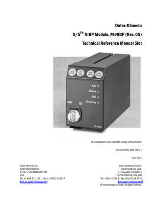
Datex-Ohmeda S/5TM NIBP Module, M-NIBP (Rev. 05) Technical Reference Manual Slot
All specifications are subject to change without notice. Document No. 800 1015-1 June 2001 Datex-Ohmeda Inc. 3030 Ohmeda Drive 53707-7550 MADISON, WIS USA Tel. +1-608-221 1551, Fax. +1-608-222 9147 www.us.datex-ohmeda.com
Datex-Ohmeda Division, Instrumentarium Corp. P.O. Box 900, FIN-00031 DATEX-OHMEDA, FINLAND Tel. +358 10 394 11 Fax +358 9 146 3310 www.datex-ohmeda.com Instrumentarium Corp. All rights reserved.
Table of contents
TABLE OF CONTENTS NIBP Module, M-NIBP TABLE OF CONTENTS
i
TABLE OF FIGURES
ii
Introduction
1
1
2
Specifications
1.1 General specifications ...2 1.2 Typical performance ...2 1.3 Technical specifications...2
2
Functional Description
4
2.1 Measurement principle ...4 2.2 Main components...4 2.2.1 NIBP board ...5 2.3 Connectors and signals...7 2.3.1 Module bus connector ...7 2.3.2 Test points ...8
3
Service Procedures
9
3.1 General service information...9 3.2 Service check ...10 3.2.1 Recommended tools ...10 3.2.2 Recommended parts ...10 3.3 Disassembly and reassembly...16 3.4 Adjustments and calibrations...17 3.4.1 Pressure safety level detection “OFFSET” ...17 3.4.2 NIBP calibrations...17
4
Troubleshooting
19
4.1 Troubleshooting chart ...19 4.2 NIBP error code explanation ...21 4.3 Troubleshooting flowchart ...22
5
Service Menu
23
5.1 NIBP Service menu ...24 5.1.1 NIBP Demo menu...25 5.1.2 NIBP Calibration menu ...26 5.1.3 NIBP Safety Valve menu ...27 5.1.4 NIBP Pulse Valve menu...28 5.1.5 NIBP Buttons/Leds menu ...29 5.1.6 NIBP Pneumatics menu ...30 5.1.7 NIBP Watchdog menu...31
6
Spare Parts
33
6.1 Spare parts list ...33 6.1.1 NIBP Module, M-NIBP Rev. 01 ...33 6.1.2 NIBP Module, M-NIBP Rev. 02 ...35 i Document No. 8001015-1
Datex-Ohmeda S/5 monitors 6.1.3 NIBP Module, M-NIBP Rev. 03...35 6.1.4 NIBP Module, M-NIBP Rev. 04...36 6.1.5 NIBP Module, M-NIBP Rev. 05...37 6.1.6 Front panel stickers for AS/3 modules (square buttons) ...37 6.1.7 Front panel stickers for S/5 modules (round buttons)...38
7
Earlier Revisions
39
APPENDIX A
41
Service check form
A-1
TABLE OF FIGURES Figure 1
Non-invasive blood pressure Module, M-NIBP ... 1
Figure 2
Front panel of NIBP Module ... 4
Figure 3
NIBP board functional block diagram ... 5
Figure 4
NIBP Module troubleshooting flowchart...22
ii Document No. 800 1015-1
NIBP Module, M-NIBP
INTRODUCTION This section provides information for the maintenance and service of the Non-Invasive Blood Pressure parameter module, M-NIBP. The Non-Invasive Blood Pressure Module, M-NIBP, is a double width plug-in module designed for use with the S/5 monitors.
Figure 1
Non-invasive blood pressure Module, M-NIBP
NOTE: Do not use identical modules in the same monitor simultaneously. The M-NIBP and MNE(12)STPR/-NESTR/-NETPR/M-MRI/M-MRIP are considered as identical modules.
1 Document No. 800 1015-1
Datex-Ohmeda S/5 monitors
1
SPECIFICATIONS
1.1 General specifications Module size, W × D × H Module weight Power consumption
75 × 180 × 112 mm/3.0 × 7.1 × 4.4 in 0.7 kg/1.5 lbs about 4 W
1.2 Typical performance Oscillometric measurement principle. Measurement range Accepted HR Measurement interval Measurement time, typical
adult 25...260 mmHg child 25...195 mmHg infant 15...145 mmHg 30...250 bpm from continuous to 1h, 2h, 4h adult 23 s infant 20 s
Initial inflation pressure
adult child infant
185 ±10 mmHg 150 ±10 mmHg 120 ±10 mmHg
Venous stasis
adult child infant
80 ±10 mmHg / 2 min 60 ±10 mmHg / 2 min 40 ±10 mmHg / 1 min
Cuff widths
Please see User’s Guide
1.3 Technical specifications Deflation rate, HR dep.
5...13 mmHg/sec
Inflation rate, typical
20...185 mmHg, 1...5 s
Automatic software control, max. inflation pressure adult 280 ±10 mmHg child 200 ±10 mmHg infant 150 ±10 mmHg Over pressure limit, stops measurement after 2 seconds adult 320 mmHg child 220 mmHg infant 165 mmHg Safety valve limits the maximum cuff pressure to 320 mmHg in adult/child mode or 165 mmHg in infant mode. Independent timing circuit limits pressurizing (>5 mmHg) time to 2 minutes 10 seconds maximum in adult/child mode, and 1 minute 5 seconds in infant mode. Zeroing to ambient pressure is done automatically. 2 Document No. 800 1015-1
NIBP Module, M-NIBP Inflation pressure is adjusted according to the previous systolic pressure, typically 40 mmHg above. If the systolic pressure is not found, inflation pressure is increased typically 50 mmHg. Max. measurement time
adult child infant
2 min. 2 min. 1 min.
Pressure transducer accuracy is better than ±3 mmHg or ±2 % (whichever is greater). Max. error ±4 mmHg. Protection against electrical shock
Type BF defibrillation proof
3 Document No. 800 1015-1
Datex-Ohmeda S/5 monitors
2
FUNCTIONAL DESCRIPTION
2.1 Measurement principle NIBP (Non-Invasive Blood Pressure) is an indirect method for measuring blood pressure. The NIBP measurement is performed according to the oscillometric measuring principle. The cuff is inflated with a pressure slightly higher than the presumed systolic pressure, and deflated at a speed based on the patient’s pulse, collecting data from the oscillations caused by the pulsating artery. Based on these oscillations, values for systolic, mean, and diastolic pressures are calculated. The following parts are necessary for NIBP measurement: NIBP module Twin hose (adult or infant model) Blood pressure cuffs (different sizes)
• • •
2.2 Main components The NIBP module consists the following parts: NIBP board Pneumatics and hosing NIBP air pump Zero valve Check valve Bleed valve Exhaust valves (2) Pressure transducers (2) Module keyboard and status indicator LEDs Front panel keys: Auto On/Off, Set Cycle Time, Stat On/Off, Start/Cancel
• • • • • • • • • •
Auto On/Off Auto Manual STAT
Set Cycle Time
Measuring
STAT On/Off NIBP
Start Cancel
Figure 2 4 Document No. 800 1015-1
Front panel of NIBP Module
NIBP Module, M-NIBP
2.2.1 NIBP board EXHAUST VALVE 1 CUFF
ZERO VALVE
EXHAUST VALVE 2
BLEED VALVE
JOINING CHAM BER
PUMP
CHECK VALVE
M
B1
B2
PRESS URE TRAN S DUCERS
P UM P and V A LV E DR IV E R
OV E RPR E S S URE CO NT RO L WATCHDO G TIM ER
A D -C O N V ER T E R
POWER -UP RESET
+ 15 VD
ADDRESS BUS CPU 80C51FA ADDRESS DECODER
to/from module bus
RS485 INTERF. X1 EEPROM (Calibration Data)
INTERNAL WATCHDO G
ADDRESS LATCH
RAM
EPROM
FRONT PANEL KEYS
SOFTWARE CONTROL
DATABUS Write protect switch
Figure 3
NIBP board functional block diagram
Pressure transducers The NIBP board contains two pressure transducers. They are of piezoresistive type. One is used for measuring the pressure of the blood pressure cuff and the pressure fluctuations caused by arterial wall movement (B1). The other is used for detection of cuff hose type, cuff loose and cuff occlusion situations etc. (B2). The transducers are internally temperature compensated. They are supplied by a constant voltage and their output voltage changes up to 40 mV max. (50 kPa, 375 mmHg).
Signal processing Two signals from the pressure transducers are amplified and sent to A/D converter. After the converter, digitized signals are sent to microprocessor for data processing. Before the converter, one of the signals is used to adjust the offset to the pressure safety level. The NIBP board is controlled with 80C51FA microprocessor at 16 MHz oscillator frequency. Communication between the module and the monitor CPU board is established through RS485 serial interface at 500 kbps data transfer rate.
5 Document No. 800 1015-1
Datex-Ohmeda S/5 monitors
Memory NIBP program memory (EPROM) size is 128k × 8. RAM size is 32k × 8 bit and it stores variable values in NIBP measurement. EEPROM is size 64 × 16 bit and is used to store the calibration values for the pressure transducers, the pulse valve constants gained during measurements, the PC board identification, and module serial number.
Software control Software controls valves and pump. In addition to the individual on/off signals for each component there is a common power switch for the valves and the pump that can be used at pump/valve failures. In addition to external RS485 reset line the microprocessor system is equipped with its own powerup reset.
Watchdog timer The NIBP board is equipped with software independent safety circuit to disconnect supply voltages from the pump and the valves if the cuff has been pressurized longer than preset time. As soon as the cuff pressure rises over a specified pressure limit, timer starts counting. The timer is adjusted to stop the pump and open the valves in 2 minutes 10 seconds in adult/child mode and in 1 minute 5 seconds in infant mode.
Valves Exhaust valves are used for emptying the cuff and the joining chamber after the measurement. Exhaust valve 1 is also used as safety valve in infant mode. Valve opens at 165 mmHg. Exhaust valve 2 is also used as safety valve in adult mode and opens at 320 mmHg. Bleed valve is used for emptying the cuff during measurement. Zero valve is used for connecting the pressure transducer B1 to open air.
Power supply section All connections are established via 25-pin connector (D-type, female). The module needs +5 V, ±15 V, and +15 VD (dirty) power supply to operate. The pump and the valves use separate +15 VD power line. The supply voltages are generated in the power supply section of the S/5 monitor. The reference voltages ±5 Vref and +10 Vref are generated on the NIBP board.
6 Document No. 800 1015-1
NIBP Module, M-NIBP
2.3 Connectors and signals 2.3.1 Module bus connector
13
1
25
14
Module Bus connector (X1) Pin No
I/O
Signal
1 2 3 4 5 6 7 8 9 10 11 12 13 14 15 16 17 18 19 20 21 22 23 24 25
I I I I I/O I/O I I O I O I I I O I O I I
RESET_RS485 -15 VDC +15 VDIRTY +15 VDC -DATA_RS485 DATA_RS485 Ground & Shield -RESET_RS485 CTSB RTSB RXDB TXDB Ground & Shield +32 VDIRTY GroundDIRTY CTSC RTSC RXDC TXDC ON/STANDBY PWM_ECG RXDD_RS232 TXDD_RS232 +5 VDC +5 VDC
Not used
* * * * * * * * * * * * *
*Not used in the M-NIBP module
7 Document No. 800 1015-1
Datex-Ohmeda S/5 monitors
2.3.2 Test points NIBP board There are test pad blocks on solder side. X8 and X6 pads and voltages are: Pump
X6 2 1
X6
X3
10 9
X5
X8
X8
2 1
X7
X8
X6
Pin No
Signal
Pin No
Signal
1 2 3 4 5 6 7 8 9 10
GND WD out reset +5 V +15 V dirty +15 V -15 V GND
1 2 3 4 5 6 7 8
GND A1 output -5V +5 V ref B1 out - (A1 input) B1 out + B2 out + B2 out -
8 Document No. 800 1015-1
8 7
NIBP Module, M-NIBP
3
SERVICE PROCEDURES
3.1 General service information Field service of the M-NIBP module is limited to replacing faulty circuit boards or mechanical parts. The circuit boards should be returned to Datex-Ohmeda for repair. Datex-Ohmeda is always available for service advice. Please provide the unit serial number, full type designation, and a detailed description of the fault.
CAUTION
Only trained personnel with the appropriate tools and equipment should perform the tests and repairs outlined in this section. Unauthorized service may void warranty of the unit.
9 Document No. 800 1015-1
Datex-Ohmeda S/5 monitors
3.2 Service check These instructions include complete procedures for a service check. The service check is recommended to be performed after any service repair. However, the service check procedures can also be used for determining possible failures. The procedures should be performed in ascending order. The instructions include a check form (Appendix A) which should be filled in when performing the procedures. The mark
? in the instructions means that the check form should be signed after performing
the procedure.
The procedures are designed for monitors with S/5 monitor software of revision 01. However, most of the procedures also apply to monitors, which contain some other monitor software type/revision.
3.2.1 Recommended tools Tool
Order No.
Notes
Part
Order No.
Notes
NIBP pump filter
57142
Pressure manometer Adult cuff & hose Infant cuff & hose Screwdriver
3.2.2 Recommended parts
•
Detach the module box by removing the two screws from the back of the module. Be careful with loose latch and spring pin for locking.
1.
Check internal parts:
10 Document No. 800 1015-1
−
screws are tightened properly
−
cables are connected properly
−
all IC’s that are on sockets are attached properly
−
EMC covers are attached properly
−
the calibration protection switch on the NIBP board is intact
−
tubes are not pinched and there are no sharp bends on them
NIBP Module, M-NIBP
−
tubes are connected properly
−
the upper of the cuff connector tubes, as well as the related tube connector are marked
−
there are no loose objects inside the module
? 2.
Check external parts: −
the front cover and the front panel sticker are intact
−
the cuff connector is intact and is attached properly
−
the module box, the latch and the spring pin are intact
? 3.
Replace the NIBP pump filter, if necessary.
? • • •
Reattach the module box and check that the latch is moving properly. Switch the monitor on and wait until the monitoring screen appears. Make sure that NIBP information is selected to be shown on the screen:
Monitor Setup - Screen 1 Setup - Digit Fields - Field 2 - NIBP 4.
5.
Plug in the module. Check that it goes in smoothly and locks up properly
?
Check that the module is recognized, i.e. the NIBP headers appear on the selected digit field.
?
6.
Enter the service menu:
Monitor Setup - Install/Service (password 16-4-34) - Service (password 26-23-8) Take down the information regarding NIBP module software by selecting Scroll Vers and turning the ComWheel.
?
11 Document No. 800 1015-1
Datex-Ohmeda S/5 monitors 7.
Enter the NIBP module service menu: Parameters - NIBP Check that the ‘Timeouts’, ‘Bad checksums’ and ‘Bad c-s by mod’ values are not increasing faster than by 50 per second. Check also that the NIBP board memories have passed the internal memory test, i.e. the ‘RAM’, ‘ROM’ and ‘EEPROM’ show all OK.
?
8.
Check the front panel LEDs and membrane keys. Select Buttons/Leds Highlight the text Auto ON. Check that the LED for the autocycle measurement is turning on and off on the module front panel when pressing the ComWheel. Check also the other LEDs by selecting Manual ON, STAT ON and Measur. ON. Press each of the module’s membrane keys at least for one second. Check that the pressed key is identified, i.e. the text OFF changes to ON for the key in the menu.
?
9.
Check the pump and valves. Select Pneumatics from the NIBP menu. Connect a pressure manometer to the NIBP module cuff connector. Highlight Start Pump and press the ComWheel. Check that the pump turns on and the pressure inside the tubing system starts to increase. Stop the pump by pressing the ComWheel again when the pressure reaches 280 mmHg. Highlight Open Exh1. Press the ComWeel and check that the pressure inside the tubing system starts to drop then press the ComWheel again. Check the other exhaust valve by the same way by selecting Open Exh2 from the menu. If necessary, turn the pump on again for a moment to increase the pressure inside the tubing system. Highlight Open Zerovalve. Press the ComWheel and check that the pressure B1 ≅ 0 mmHg. Close the zero valve by pressing the ComWheel again and check that the pressure B1 is equal with the pressure B2. Highlight Set Valve. Press the ComWheel and set the value under the text ‘Pulse Valve’ to number 150 by turning the ComWheel. Press the ComWheel again and check that the pressure inside the tubing system starts to drop. Finish the test by selecting Previous Menu.
? 12 Document No. 800 1015-1
NIBP Module, M-NIBP 10.
Check the NIBP tubing system for leakages. Select Calibrations from the NIBP service menu. Keep the pressure manometer connected to the NIBP module cuff connector. Start the active leak test from the menu by pressing the ComWheel. The module pumps a pressure of about 265 mmHg and then the pump stops. Wait for 15 seconds for the pressure to stabilize then check that the pressure does not drop more than 5 mmHg per one minute. Release the pressure by pressing the ComWheel once more.
? 11.
Calibration check. Disconnect the pressure manometer. Select Calibrations and then highlight Calibration Check. Press the ComWheel and take down the zero offset values for both pressure transducers, B1 and B2. The values should be within ±10 mmHg. Connect the pressure manometer to the cuff connector and check the calibration with pressures 100 mmHg, 200 mmHg and 260 mmHg. The zero offset value must be added to the displayed pressure value in order to determine the real pressure. Recalibrate the NIBP measurement according to the instructions in the Technical Reference Manual, if necessary. Remember to set the calibration protection back on after the calibration.
? 12.
Check the watchdog timer activation pressure. Select Pneumatics from the NIBP service menu. Keep the pressure manometer connected to the cuff connector. Pump up the pressure very slowly and note the value on the manometer when your hear a signal from the loudspeaker. The pressure at where the watchdog timer should activate with an audible signal is Rev. 00-03 = 14 mmHg (9...19 mmHg) Rev. 04 -> = 7.5 mmHg (5...10 mmHg) Adjust the limit with the trimmer on the NIBP board, if necessary.
13.
?
Check the watchdog timer. Select Watchdog from the NIBP service menu. Check the watchdog timer in the adult mode. Activate the timer by highlighting Test ADULT and then pressing the ComWheel. Check that the time beside the text ‘Watchdog Interval’ starts to run. Wait until you hear a signal from the loudspeaker and then check the time again. The time from the adult test should fall within 120...140 seconds. 13 Document No. 800 1015-1
Datex-Ohmeda S/5 monitors Check the watchdog timer also in the infant mode by first selecting Test INFANT from the menu. The time from the infant test should fall within 60...70 seconds.
? 14.
Check the safety valve. Select Safety Valve from the NIBP service menu. Keep the pressure manometer connected to the cuff connector. NOTE: Make sure your pressure manometer can be used to measure pressures over 300 mmHg. If such a pressure manometer is not available, perform the check with an adult cuff that is connected around some round object, for example calibration gas bottle. Highlight Start Test. Start the adult safety valve test by pressing the ComWheel. Wait until the pump stops and the pressure is deflated. Check the pressure values ‘Max press’ and ‘2 s after stop’ for both transducers. All the values should be within 290...330 mmHg. Highlight Adult. Press the ComWheel and check that the text changes now to Infant. Select Start Test and wait until the pump stops and the pressure values on the screen have been updated. Check that the values ‘Max press’ and ‘2 s after stop’ are all now within 154...165 mmHg. Return to the normal monitoring mode by pressing Normal Screen.
?
15.
Connect an adult NIBP cuff to the cuff connector and disconnect one of its hoses. Start NIBP measurement by pressing the key Start/Cancel on the module and check that the message ‘Cuff loose’ appears on the screen within 30 seconds. Reconnect the hose and then bend it with your fingers. Restart the measurement and check that the message ‘Cuff occlusion’ appears on the screen within 30 seconds.
?
16.
Check that automatic inflation limits are in use:
NIBP - NIBP Setup - Inflation Limits - Auto - Previous Menu Connect the cuff onto your arm, highlight Start Ven.Stasis in the NIBP menu and press the ComWheel. Check the module identifies the cuff, i.e. the text ‘Adult’ appears into the NIBP digit field for a short moment. Keep the pressure inside the cuff for about half a minute in order to see that the cuff is not leaking, then press the ComWheel again. Select Normal Screen.
? 14 Document No. 800 1015-1
NIBP Module, M-NIBP 17.
Keep the cuff on your arm and perform one NIBP measurement. Check that the module gives a reasonable measuring result.
? 18.
Connect an infant cuff to cuff connector and wrap it around your fingers. Start NIBP measurement and check that the module identifies the cuff, i.e. the text ‘Infant’ appears into the NIBP digit field. Cancel the measurement after the cuff identification.
?
19.
Perform electrical safety check and leakage current test.
20.
Check that the module functions normally after the performed electrical safety check.
21.
Clean the module with suitable detergent.
•
Fill in all necessary documents.
? ? ?
15 Document No. 800 1015-1
Datex-Ohmeda S/5 monitors
3.3 Disassembly and reassembly Rev. 01-03
Rev. 04 ->
CAUTION
Disassemble the M-NIBP module in the following way. See the exploded view of the module. 1.
Remove the two screws from the back of the module.
2.
Pull the module box slowly rearward and detach it from main body. Be careful with loose latch and spring pin for locking.
3.
To detach the NIBP board remove the four corner screws from the back of NIBP board. The NIBP board and the front panel can be detached.
4.
To free the front panel and the NIBP board, disconnect tubes and connectors.
5.
Remove the five screws and lift off the plastic pump cover. NIBP pump, safety (over pressure) valve, and valve unit which includes two valves, wires and a connector will be exposed. Remove them.
6.
Pull out pulse valve from the bottom of the NIBP frame.
Disassemble the M-NIBP module in the following way. See the exploded view of the module. 1.
Remove the two screws from the back of the module.
2.
Pull the module box slowly rearward and detach it from main body. Be careful with loose latch and spring pin for locking.
3.
To detach the NIBP board remove the support plate by 2 screws (item 25).
4.
Remove the metal frame (item 26).
5.
Detach the damping chamber with 3 screws.
6.
Detach 2 screws (item 9).
7.
To free the front panel and the NIBP board, disconnect tubes and connectors.
8.
Remove the two screws and lift off the pump. NIBP pump, and valve unit which includes four valves, wires and a connector will be exposed. Remove them.
Before reattaching the module box, make sure that the tubes are not pinched between the NIBP frame and the PC board. NOTE: Take care that the connectors and especially the tubes are reconnected properly and to the right ports.
16 Document No. 800 1015-1
NIBP Module, M-NIBP
3.4 Adjustments and calibrations 3.4.1 Pressure safety level detection “OFFSET” Remove two screws at the rear of the module. Remove the module box. Connect first the service cable (e.g. a long Gas interface cable) to the module connector inside the monitor frame and then to the rear connector of the module. Switch the monitor on. Go to the NIBP service menu and select Pneumatics. Pump reference pressure into the module: Rev. 00-03 = 14 mmHg (9...19 mmHg) Rev. 04 -> = 7.5 mmHg (5...10 mmHg) Adjust the trimmer until AD5 signal sign changes from negative to positive. Re-check the adjustement, then lock the trimmer with for example nail polish.
3.4.2 NIBP calibrations The electronics of NIBP pressure measurement is calibrated at the factory. Zeroing pressure is automatically maintained by the processor. If the zero point of the pressure transducer drifts more than specified, an error message is given and the NIBP board should be recalibrated or replaced. The calibration can be checked and recalibrated in the NIBP service menu. The calibration of the primary pressure channel can also be checked from the NIBP setup menu (NIBP, NIBP Setup, Calibration Check). In this case the auto zeroing is performed at start - remove hose before entering to ensure atmospheric pressure to the pressure transducers - the primary pressure is displayed. The zero-offset value should then be zero.
Calibration check 1.
Enter Calibration menu.
2.
Select ‘Calibration Check’ and press the ComWheel.
3.
Connect an external precision manometer to the module.
4.
Pump the following pressures to manometer and check the difference between the manometer and monitor pressure display:
17 Document No. 800 1015-1