Service Manual
282 Pages
Preview
Page 1
GE Healthcare
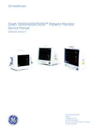
Dash 3000/4000/5000™ Patient Monitor Service Manual Software Version 7
Dash 3000/4000/5000 English 2023909-014 (CD) 2023896-104 (paper) © 2011, 2013 General Electric Company All rights reserved
NOTE: The information in this manual only applies to Dash 3000/4000/5000 patient monitors with software version 7. It does not apply to earlier software versions. Due to continuing product innovation, specifications in this manual are subject to change without notice. NOTE: The assembly drawings in this manual only support patient monitors with the SHQ product code. Patient monitors with the SHQ product code are only compatible with software version 6.10 or later. NOTE: Wireless LAN troubleshooting procedures are specific to the wireless LAN technology installed on the patient monitor. For Dash patient monitors with the LA-4137 wireless LAN hardware (identified on the Dash wireless LAN transmitter label), and Dash version 7 or later software, follow the wireless LAN troubleshooting instructions found in the service manual you received with your patient monitor. NOTE: The 802.11 a/b/g wireless feature is only compatible with Dash 3000/4000/5000 patient monitors with software version 7 or later. NOTE: The Dash Port 2 docking station with version 2.1 or later software is only compatible with the Dash 3000/4000/5000 patient monitor with version 7.2 or later software. NOTE: For technical documentation purposes, the abbreviation GE is used for the legal entity name, GE Medical Systems Information Technologies, Inc. Listed below are GE Medical Systems Information Technologies, Inc. trademarks. All other trademarks contained herein are the property of their respective owners. DASH, DINAMAP, EAGLE, MULTI-LINK, MUSE, SAM, SOLAR, TRIM KNOB, and UNITY NETWORK are trademarks of GE Medical Systems Information Technologies, Inc., registered in the United States Patent and Trademark Office. 12SL, CARESCAPE, CENTRALSCOPE, INTELLIRATE, MENTOR, and SUPERSTAT are trademarks of GE Medical Systems Information Technologies, Inc.
T-2
Dash 3000/4000/5000
2000966-542D 22 April 2013
Contents
1
Introduction... 1-1 Manual information... 1-2 Revision history... 1-2 Manual purpose... 1-2 Intended audience... 1-2 Ordering manuals... 1-2 Safety information... 1-3 Responsibility of the manufacturer... 1-3 General... 1-3 Warnings, cautions, and notes... 1-4 Equipment symbols... 1-5 Service information... 1-9 Service requirements... 1-9 Equipment identification... 1-9
2
Equipment overview... 2-1 Components... 2-2 Monitoring system... 2-2 Patient monitor... 2-2 Controls and indicators... 2-6 Exchangeable or compatible battery packs... 2-9 Optional components... 2-10 Optional remote control... 2-13 Software packages and software options... 2-14 Software packages... 2-14 Software options... 2-14 Ethernet communication... 2-15 About Ethernet... 2-15 Twisted pair... 2-15 Network Terms... 2-16 Theory of operation... 2-17 Components... 2-17 Overall patient monitor block diagram... 2-17 Power supply... 2-18 Data Acquisition System (DAS)... 2-18
2000966-542D
Dash 3000/4000/5000
i
Processor/power management subsystem... 2-27 Lithium-Ion battery power... 2-35 Speaker... 2-40 Handle subassembly... 2-40 Interfaces... 2-40 Storage and backup... 2-42 Optional thermal printer... 2-43
3
Installation... 3-1 Installation overview... 3-2 Inspection... 3-3 Before you begin... 3-4 Connections... 3-5 Back panel connections... 3-5 Power up... 3-7 Configure... 3-7 Dash installation checkout procedure... 3-8
4
Configuration... 4-1 Before you begin... 4-2 Service menus... 4-3 Boot Loader Service Menu... 4-4 Main menu service mode... 4-5 Procedures... 4-9 Set print locations... 4-10 Service Mode settings... 4-11 Set Unit Name... 4-11 Set Bed Number... 4-11 Patient-Monitor Type... 4-12 Admit Menu... 4-13 Confirm or configure wireless LAN... 4-14 Boot Code settings... 4-18 Set Defib Sync Voltage and pulse width... 4-18 Set Line Frequency... 4-18 Set CIC and QS protocol... 4-19 Set MUSE system protocol... 4-19
ii
Dash 3000/4000/5000
2000966-542D
Transcutaneous Pace Blank Length... 4-19 Set Country Selection... 4-20 Set Language... 4-20 Enable or disable AFIB Identification... 4-21 Enable or disable IntelliRate... 4-21 Analog Out Buzz... 4-22 Completion... 4-22 Advanced user procedures... 4-23 Procedures... 4-23 Set time and date... 4-23 Transfer monitor defaults... 4-24
5
Preventive maintenance... 5-1 Maintenance schedule... 5-2 Visual inspection... 5-3 Cleaning and disinfecting the patient monitor... 5-3 Procedure... 5-3 Cautions... 5-4 Impact or results of improper cleaning products and processes... 5-5 Cleaning products to avoid... 5-5 Storage... 5-5 Clean the print head... 5-6 Cleaning, disinfecting and storing GE ECG cables and leadwires... 5-7 Cleaning and disinfecting... 5-7 Sterilization... 5-8 Cautions... 5-8 Storage... 5-8 Improper cleaning products and processes impact or results... 5-8 Cleaning products to avoid... 5-9 Cleaning other applied parts... 5-9 Battery maintenance... 5-10 How to charge the battery... 5-10 How to condition the battery... 5-11 How to store the battery... 5-12 How to wake up the battery... 5-12 How to replace the batteries... 5-14 Rechargeable battery recycling... 5-15 About the Cadex SMart Two+ charger... 5-16 Clear the stored patient data memory... 5-17
2000966-542D
Dash 3000/4000/5000
iii
6
Troubleshooting... 6-1 Fault analysis... 6-2 Overview... 6-2 Required tools or equipment... 6-2 Problems... 6-2 Acquisition PCB symptoms... 6-4 Processor PCB symptoms... 6-4 Error messages... 6-5 Battery alarms and messages... 6-7 Battery messages displayed in the ECG waveform area... 6-7 Battery messages displayed in the Battery Status information window... 6-8 Battery Messages Displayed in the Battery Fuel Gauge Icon... 6-8 Writer or printer... 6-9 External... 6-9 Internal... 6-9 No waveform at central station... 6-10 Monitor defaults transfer... 6-11 Storing monitor defaults... 6-11 Copying stored monitor defaults... 6-11 Change internet address... 6-12 Review errors... 6-13 View output or input errors... 6-13 Useful error data... 6-14 Get error logs... 6-16 Get logs via PC using netUpdate... 6-16 Get logs via CIC... 6-21 Get logs via Centralscope... 6-21 Wireless LAN... 6-24 Access Service Mode... 6-25 Identify the wireless technology... 6-25 802.11a/b/g... 6-26
7
Field replaceable units... 7-1 Ordering field replaceable units... 7-2 Field replaceable units... 7-3
iv
Dash 3000/4000/5000
2000966-542D
Disassembly guidelines... 7-7 Tools required... 7-7 Before disassembly... 7-7 Hardware precautions... 7-8 Electrostatic discharge (ESD) precautions... 7-8 Replacement procedures... 7-9 Remove or replace handle assembly... 7-10 Remove or replace display assembly... 7-18 Replace display flex assembly... 7-24 Replace display assembly parts... 7-26 Open display assembly... 7-27 Replace Dash 4000/5000 alarm light... 7-28 Replace display inverter... 7-28 Replace keypad assembly or Trim Knob control... 7-30 Replace display components without LCD... 7-31 Replace main unit parts... 7-34 Replace wireless card... 7-34 Replace DAS assembly... 7-37 Replace NBP pump assembly... 7-40 Replace writer assembly or writer flex... 7-41 Replace speaker assembly... 7-42 Replace CPU/battery housing assembly... 7-44 Replace power supply assembly... 7-48 Replace battery door... 7-50 Replace foot... 7-50 Replace writer cover... 7-51 Recommended checkout... 7-52
8
Functional and electrical safety checks... 8-1 Overview... 8-2 Manufacturer recommendations... 8-2 Frequency... 8-2 Test equipment... 8-2 Functional Checkout procedures... 8-3 Electrical safety tests... 8-4 General... 8-4 Recommendations... 8-4 Power outlet test... 8-5
2000966-542D
Dash 3000/4000/5000
v
Power cord and plug... 8-5 Ground (earth) integrity... 8-6 Ground (earth) wire leakage current tests... 8-7 Enclosure (Touch) leakage current test... 8-9 Patient (source) leakage current test... 8-12 Patient (sink) leakage current test (mains voltage on the applied part)... 8-14 BISx (option) current leakage tests... 8-16 BISx patient (source) leakage current test... 8-16 BISx patient (sink) leakage current test... 8-18 Test completion... 8-19 Functional Checkout procedures... 8-20 Frequency... 8-20 Identify enabled patient parameters and software options... 8-20 Patient monitor power-up tests... 8-21 ECG tests... 8-22 Respiration tests... 8-25 Temperature tests... 8-26 Cardiac output tests (option)... 8-27 Invasive blood pressure tests (option)... 8-27 Pulse oximetry tests for GE Ohmeda SPO2 oximeter... 8-30 Pulse oximetry tests for Masimo SET SPO2... 8-32 Pulse oximetry tests for Nellcor OxiMax SPO2... 8-33 Noninvasive blood pressure tests... 8-35 NBP calibration... 8-37 Analog output and defibrillator synchronization tests... 8-40 End-tidal CO2 test (option)... 8-44 Battery tests... 8-44 Graph or print tests (option)... 8-44 Display test... 8-45 Speaker test... 8-46 Network test (option)... 8-46 Remote control test (option)... 8-46 BISx test (option)... 8-47 Wireless antenna signal strength test (option)... 8-49 Wireless LAN test (option)... 8-52 Dash Port 2 docking station test (option)... 8-54 TRAM-rac 2A module housing peripheral device test (option)... 8-54 ICG Module test (option)... 8-54 Checkout procedures completion... 8-55
vi
Dash 3000/4000/5000
2000966-542D
A
Electromagnetic compatibility (EMC)...A-1 Electromagnetic compatibility (EMC)... A-2 Guidance and manufacturer’s declaration – electromagnetic emissions...A-2 Guidance and manufacturer’s declaration – electromagnetic immunity...A-3 Guidance and manufacturer’s declaration – electromagnetic immunity...A-5 Recommended separation distances...A-6 Compliant cables and accessories...A-7
B
Network troubleshooting...B-1 Network traffic... B-2 Traffic types...B-2 Flow...B-2 Network infrastructure compatibility... B-3 Compatible wireless network infrastructures...B-3 Problem: No waveforms or parameters are displayed at the CIC Pro center . . . B-5
C
Network disclosure to facilitate network risk management...C-1 Purpose and scope...C-2 Purpose for the Dash patient monitor connection to network...C-2 Dash patient monitor network interface technical specifications...C-2 Network information flows...C-5 Required characteristics and configuration of network for support of Dash patient monitor...C-6 Potential risks to safety, effectiveness or security resulting from failure of IT network to provide the required characteristics...C-7
D
Checklist...D-1 Checklist... D-2
2000966-542D
Dash 3000/4000/5000
vii
viii
Dash 3000/4000/5000
2000966-542D
1
2000966-542D
Introduction
Dash 3000/4000/5000
1-1
Introduction: Manual information
Manual information Revision history Each page of this manual has the document part number and revision letter at the bottom of the page. The revision letter identifies the document’s update level. The revision history of this document is summarized below.
Revision
Comment
A
Initial release of this manual.
B
Updated WLAN a/b/g instructions.
C
Added Appendix C - Network disclosure, updated Dash Port 2 software compatibility, updated Windows workflows, and generalized disabling firewall/network services workflows.
D
Updated FRU kits.
Manual purpose This manual supplies technical information for service representatives and technical personnel so they can maintain the equipment to the assembly level. Use it as a guide for maintenance and electrical repairs considered field repairable. Where necessary the manual identifies additional sources of relevant information and technical assistance. See the operator’s manual for the instructions necessary to operate the equipment safely in accordance with its function and intended use.
Intended audience This manual is intended for service representatives and technical personnel who maintain, troubleshoot, or repair this equipment.
Ordering manuals A paper copy of this manual will be provided upon request. Contact your local GE representative and request the part number on the first page of the manual.
1-2
Dash 3000/4000/5000
2000966-542D
Introduction: Safety information
Safety information Responsibility of the manufacturer GE is responsible for the effects of safety, reliability, and performance only if:
Assembly operations, extensions, readjustments, modifications, or repairs are carried out by persons authorized by GE.
The electrical installation of the relevant room complies with the requirements of the appropriate regulations.
The equipment is used in accordance with the instructions for use.
General This device is intended for use under the direct supervision of a licensed health care practitioner. This device is not intended for home use. Federal law restricts this device to be sold by or on the order of a physician. Contact GE for information before connecting any devices to the equipment that are not recommended in this manual. Parts and accessories used must meet the requirements of the applicable IEC 60601 series safety standards, and/or the system configuration must meet the requirements of the IEC 60601-1-1 medical electrical systems standard. Periodically, and whenever the integrity of the device is in doubt, test all functions. The use of accessory equipment not complying with the equivalent safety requirements of this equipment may lead to a reduced level of safety of the resulting system. Consideration relating to the choice shall include:
use of the accessory in the patient vicinity; and
evidence that the safety certification of the accessory has been performed in accordance to the appropriate IEC 60601-1 and/or IEC 60601-1-1 harmonized national standard.
If the installation of the equipment, in the USA, will use 240V rather than 120V, the source must be a center-tapped, 240V, single-phase circuit.
2000966-542D
Dash 3000/4000/5000
1-3
Introduction: Safety information
Warnings, cautions, and notes The terms danger, warning, and caution are used throughout this manual to point out hazards and to designate a degree or level or seriousness. Familiarize yourself with their definitions and significance. Hazard is defined as a source of potential injury to a person. DANGER indicates an imminent hazard which, if not avoided, will result in death or serious injury. WARNING indicates a potential hazard or unsafe practice which, if not avoided, could result in death or serious injury. CAUTION indicates a potential hazard or unsafe practice which, if not avoided, could result in minor personal injury or product/property damage. NOTE provides application tips or other useful information to assure that you get the most from your equipment.
1-4
Dash 3000/4000/5000
2000966-542D
Introduction: Equipment symbols
Equipment symbols NOTE: Some symbols may not appear on all equipment. ATTENTION: Consult accompanying documents before using the equipment. In Europe, this symbol means dangerous or high voltage. In the United States, this symbol represents the caution notice below: To reduce the risk of electric shock, do not remove cover (or back). Refer servicing to qualified personnel. Defibrillator-proof type CF equipment; type CF equipment is specifically designed for applications where a conductive connection directly to the heart is established. The paddles indicate the equipment is defibrillator proof. Defibrillator-proof type BF equipment; type BF equipment is suitable for intentional external and internal application to the patient, excluding direct cardiac application. Type BF equipment is type B equipment with an F-type isolated (floating) part. The paddles indicate the equipment is defibrillator proof. Type B equipment; type B equipment is suitable for intentional external and internal application to the patient, excluding direct cardiac application.
Equipotential Stud: A ground wire from another device can be tied here to ensure the devices share a common reference.
Alternating current (AC)
Power; I = ON; O= OFF
Fuse
Battery
Indicates the Ethernet connection for the patient monitor.
POWER (Dash 4000)
2000966-542D
Dash 3000/4000/5000
1-5
Introduction: Equipment symbols
Power (Dash 5000)
Standby (Dash 5000)
Main Display (Dash 5000)
Trend (Dash 5000)
Admit/Discharge (Dash 5000)
Print (Graph Go/Stop on older Dash 3000/4000)
NBP Go/Stop (on older Dash 3000/4000)
NBP Auto (Dash 5000)
Zero All
Silence Alarm/Admit
4P41
Medical Equipment With respect to electric shock, fire and mechanical hazards only in accordance with UL 60601-1, CAN/CSA C22.2 NO. 601, IEC 60601-1, IEC 60601-2-27, IEC 60601-2-30, IEC 60601-2-34, and IEC 60601-2-49. This symbol indicates that the waste of electrical and electronic equipment must not be disposed as unsorted municipal waste and must be collected separately. Please contact an authorized representative of the manufacturer for information concerning the decommissioning of your equipment. This product consists of devices that may contain mercury, which must be recycled or disposed of in accordance with local, state, or country laws. (Within this system, the backlight lamps in the monitor display contain mercury.)
1-6
Dash 3000/4000/5000
2000966-542D
Introduction: Equipment symbols
This symbol indicates the date of manufacture of this device. The first four digits identify the year and the last two digits identify the month. 2005-08 Non-ionizing electromagnetic radiation: To indicate elevated, potentially dangerous, levels of non-ionizing radiation. Note - In case of application in a warning sign the rules according to ISO 3864-1 shall be adhered to. IEC 60878 note: See safety sign ISO 7010 - W005 “Warning, non-ionizing radiation”. FCC. USA only. Complies with applicable US government (Federal Communications Commission) radio-frequency interference regulations.
Manufacturer name and address.
Device serial number.
Russia only. GOST-R certification, where XXXX indicates the four-digit certification body number determined by product.
Catalog or orderable part number.
European authorized representative.
Prescriptive device. USA only. For use by or on the order of a physician, or persons licensed by state law.
CAUTION - Safety ground precaution. Remove power cord from the mains source by grasping the plug. Do not pull on the cable.
2000966-542D
Dash 3000/4000/5000
1-7
Introduction: Equipment symbols NOTE The following symbols (required by China law only) are representative of what you may see on your equipment. The number in the symbol indicates the EFUP period in years, as explained below. Check the symbol on your equipment for its EFUP period. This symbol indicates the product contains hazardous materials in excess of the limits established by the Chinese standard SJ/T11363-2006 Requirements for Concentration Limits for Certain Hazardous Substances in Electronic Information Products. The number in the symbol is the Environment-friendly User Period (EFUP), which indicates the period during which the toxic or hazardous substances or elements contained in electronic information products will not leak or mutate under normal operating conditions so that the use of such electronic information products will not result in any severe environmental pollution, any bodily injury or damage to any assets. The unit of the period is “Year”. In order to maintain the declared EFUP, the product shall be operated normally according to the instructions and environmental conditions as defined in the product manual, and periodic maintenance schedules specified in Product Maintenance Procedures shall be followed strictly. Consumables or certain parts may have their own label with an EFUP value less than the product. Periodic replacement of those consumables or parts to maintain the declared EFUP shall be done in accordance with the Product Maintenance Procedures. This product must not be disposed of as unsorted municipal waste, and must be collected separately and handled properly after decommissioning. This symbol indicates that this electronic information product does not contain any toxic or hazardous substance or elements above the maximum concentration value established by the Chinese standard SJ/T11363-2006, and can be recycled after being discarded, and should not be casually discarded.
1-8
Dash 3000/4000/5000
2000966-542D
Introduction: Service information
Service information Service requirements Follow the service requirements listed below.
Refer equipment servicing to GE-authorized service personnel only.
Any unauthorized attempt to repair equipment under warranty voids that warranty.
It is the user’s responsibility to report the need for service to GE or to one of their authorized agents.
Failure on the part of the responsible individual, hospital, or institution using this equipment to implement a satisfactory maintenance schedule may cause undue equipment failure and possible health hazards.
Regular maintenance, irrespective of usage, is essential to ensure that the equipment will always be functional when required.
Equipment identification Every GE device has a unique serial number for identification. A sample of the information found on a serial number label is shown below.
### ## ## #### # #
A
B
C
D
E
F
Description A
product code1
B
year manufactured
C
fiscal week manufactured
D
production sequence number
E
manufacturing site
F
miscellaneous characteristic 1. The current Dash patient monitor product code is SHQ. Dash 3000/4000/5000 patient monitors with the SHQ product code are only compatible with software version 6.10 or later.
2000966-542D
Dash 3000/4000/5000
1-9
Introduction: Service information
1-10
Dash 3000/4000/5000
2000966-542D