GE
Datex-Ohmeda S5 Monitor Series
S5 Anesthesia and Critical Care Monitor Technical Reference Manual June 2005
Technical Reference Manual
524 Pages
Preview
Page 1
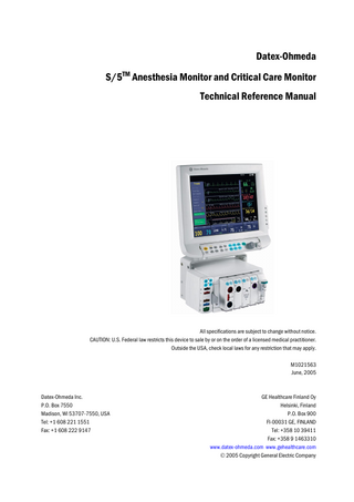
Datex-Ohmeda S/5TM Anesthesia Monitor and Critical Care Monitor Technical Reference Manual
All specifications are subject to change without notice. CAUTION: U.S. Federal law restricts this device to sale by or on the order of a licensed medical practitioner. Outside the USA, check local laws for any restriction that may apply. M1021563 June, 2005
Datex-Ohmeda Inc. P.O. Box 7550 Madison, WI 53707-7550, USA Tel: +1 608 221 1551 Fax: +1 608 222 9147
GE Healthcare Finland Oy Helsinki, Finland P.O. Box 900 FI-00031 GE, FINLAND Tel: +358 10 39411 Fax: +358 9 1463310 www.datex-ohmeda.com www.gehealthcare.com © 2005 Copyright General Electric Company
Intended purpose (Indications for use) The Datex-Ohmeda S/5 Anesthesia Monitor with L-ANE05 or L-ANE05A software is intended for multiparameter patient monitoring with optional patient care documentation. The S/5 Anesthesia Monitor with L-ANE05 and L-ANE05A software is indicated for monitoring of hemodynamic (including arrhythmia and ST-segment analysis), respiratory, ventilatory, gastrointestinal/regional perfusion, Bispectral index (BIS), Entropy (State Entropy and Response Entropy) and neurophysiological status of all hospital patients. The S/5 Anesthesia Monitor with L-ANE05 and L-ANE05A software when using BIS is for monitoring the state of the brain by data acquisition and processing of electroencephalograph signals and may be used as an aid in monitoring the effects of certain anesthetic agents. The S/5 Anesthesia Monitor with L-ANE05 and L-ANE05A software is also indicated for documenting patient care related information. The S/5 Anesthesia Monitor with L-ANE05 and L-ANE05A software is indicated for use by qualified medical personnel only. The Datex-Ohmeda S/5 Critical Care Monitor with L-ICU05 or L-ICU05A software is intended for multiparameter patient monitoring. The S/5 Critical Care Monitor with L-ICU05 and L-ICU05A software is indicated for monitoring of hemodynamic (including arrhythmia and ST-segment analysis), respiratory, ventilatory, gastrointestinal/regional perfusion, Bispectral index (BIS) and neurophysiological status of all hospital patients. The S/5 Critical Care Monitor with L-ICU05 and L-ICU05A software when using BIS is for monitoring the state of the brain by data acquisition and processing of electroencephalograph signals and may be used as an aid in monitoring the effects of certain anesthetic agents. The S/5 Critical Care Monitor with L-ICU05 and L-ICU05A software is indicated for use by qualified medical personnel only.
Classifications In accordance with IEC 60601-1 Class I and internally powered equipment – the type of protection against electric shock. Type BF or CF equipment. The degree of protection against electric shock is indicated by a symbol on each parameter module. Equipment not suitable for use in the presence of a flammable anesthetic mixture with air or with oxygen or nitrous oxide. Continuous operation according to the mode of operation. In accordance with IEC 60529 With F-CU8 Central Unit: IPX0 - the degree of protection against harmful ingress of water. With F-CU5(P) Central Unit: IPX1 - the degree of protection against harmful ingress of water. In accordance with EU Medical Device Directive The Datex-Ohmeda S/5 Anesthesia Monitor is classified as IIb. The Datex-Ohmeda S/5 Critical Care Monitor is classified as IIb. In accordance with CISPR 11: Group 1, Class B (F-CU5(P), F-CPU and N-AC: Class A)
• Group 1 contains all ISM (industrial, scientific and medical) equipment in which there is intentionally generated and/or used conductively coupled radio-frequency energy which is necessary for the internal functioning of the equipment itself.
• Class B equipment is suitable for use in domestic establishments and in establishments directly connected to a low voltage power supply network which supplies buildings used for domestic purposes.
• Class A equipment is suitable for use in all establishments other than domestic and those directly connected to a low voltage power supply network which supplies buildings used for domestic purposes.
Responsibility of the manufacturer GE Healthcare Finland Oy (GE) is responsible for the safety, reliability and performance of the product only if:
• modifications, service and repairs are carried out by personnel authorized by GE. • the electrical installation of the room complies with appropriate requirements. • the equipment is used in accordance with the User's Guide and serviced and maintained in accordance with the Technical Reference Manual.
Master table of contents
Datex-Ohmeda S/5TM Anesthesia and Critical Care Monitors Technical Reference Manual, Order code: M1021563 Part I, General Service Guide Document No.
Updated
Description
M1027807
Introduction, System description, Installation, Interfacing, Functional check, General troubleshooting
1
M1027808
Planned Maintenance Instructions
2
Part II, Product Service Guide Document No.
Updated
Description
M1027809
AM, CCM Service Menu
1
M1027810
8-Module Frame, F-CU8
2
M1027811
5-Module Frame, F-CU5(P)
3
M1027812
CPU Board, B-CPU5
4
M1027813
UPINET Board, B-UPI4NET
5
M1023412
Displays and Display Controller Boards
6
M1027814
Command Boards and Bars
7
M1027815
Interface Board, B-INT
8
M1027816
Extension Frame, F-EXT, Extension Module, M-EXT
9
M10 39372
AM, CCM Spare Parts
10
Datex-Ohmeda S/5 Anesthesia and Critical Care Monitors
Table of contents
Table of contents About this manual
1
1
3
Introduction 1.1
1.2
2
System description 2.1 2.2 2.3 2.4 2.5 2.6
3
Symbols... 4 1.1.1 Symbols on transport packaging... 4 1.1.2 Symbols on equipment... 4 1.1.3 Equipment safety symbols... 5 1.1.4 Other symbols... 7 Safety... 9 1.2.1 Safety precautions... 9 1.2.2 ESD precautionary procedures...12 1.2.3 Disposal...12 Introduction...13 Bus structure...13 Distributed processing...14 Module communication...14 Software loading...15 Parameter modules...16
System installation 3.1 3.2 3.3
3.4
3.5
13
17
Unpacking instructions...17 Choosing location...17 Central Unit; S/5 8-Module Frame, F-CU8...17 3.3.1 Connecting to mains...18 3.3.2 Connecting to Datex Ohmeda Network...18 3.3.3 Inserting the parameter modules...18 3.3.4 Positioning of PC boards...20 3.3.5 Replacing PC Boards...20 3.3.6 Performing Factory Reset...21 Central Unit; S/5 5-Module Frame, F-CU5...22 3.4.1 Mounting the Frame...23 3.4.2 Connecting to mains...24 3.4.3 Connecting to Datex Ohmeda Network...24 3.4.4 Inserting the Parameter Modules...25 3.4.5 Positioning the PC boards...26 3.4.6 Replacing PC boards...27 3.4.7 Performing Factory Reset...27 Displays...28 3.5.1 Main displays...28 3.5.2 Secondary displays...28 3.5.3 3rd display...29 3.5.4 Display installation...29 3.5.5 S/5 Video Display, D-VMC15...29 3.5.6 S/5 LCD Display, D-LCC15...30
i Document no. M1027807
Datex-Ohmeda S/5 Anesthesia and Critical Care Monitors
3.6 3.7 3.8
3.9 3.10 3.11
4
3.5.7 15” Video Display, D-VNC15...31 3.5.8 17” Video Display, D-VHC17, revision 00-01...32 3.5.9 17” Video Display, D-VHC17, revision 02-03...32 3.5.10 10” LCD Display, D-LCC10A/W...32 3.5.11 12” LCD Display, D-LCC12A...33 3.5.12 S/5 LCD Display, D-LCC17...33 3.5.13 S/5 LCD Display, D-LCC19...34 3.5.14 21" Display Monitor Unit, D-VSC21...36 3.5.15 42” Plasma Display, D-MPP42 and 43" Plasma Display, D-MMP43...36 Display controller boards...37 3.6.1 Jumper settings...37 3.6.2 Resolution selection for B-DISPX...40 S/5 Remote Controller, K-REMCO...40 S/5 Airway Modules...41 3.8.1 S/5 Compact Airway Modules, E-xxxx / M-xxxxx...41 3.8.2 S/5 Airway Modules, G-XXXX, with Central Unit F-CU8 only...41 3.8.3 Sample gas exhaust...42 Record Keeping Keyboard for Anesthesia, K-ARKB...44 3.9.1 Connection to Central Unit...44 3.9.2 Connection to LCD Display, D-LCC10A/W and D-LCC12A...44 ARK Barcode Reader, N-SCAN (optional)...44 3.10.1 Connection to Central Unit/LCD Display, D-LCC10A/W or D-LCC12A...44 S/5 Extension Frame, F-EXT4, with F-CU8 only...46 3.11.1 Mounting of Extension Frame, F-EXT4...46 3.11.2 Connection to Central Unit...46 3.11.3 Inserting parameter modules...46 3.11.4 Troubleshooting...47
Interfacing 4.1
4.2
4.3
4.4
48
Interfacing external monitors via Interface Module, E-INT / M-INT, or Interface Board, B-INT...48 4.1.1 Connecting interface connector cables to Interface Board, B-INT...49 4.1.2 Connection to external Datex-Ohmeda monitors...50 4.1.3 Connection to Critikon Dinamap 1846SX, Abbott Oximetrix 3 and Baxter Explorer...50 4.1.4 Connection to Baxter Vigilance...50 4.1.5 Connection to Nellcor N-100 and N-1000...51 4.1.6 Connection to Nellcor N-200...51 Interfacing external bedside devices via S/5 Device Interfacing Solutions, N-DISxxx...52 4.2.1 Device Interfacing Solution components...53 4.2.2 Connections...53 4.2.3 Mounting...54 4.2.4 Selecting the external device...55 4.2.5 Functional check...55 4.2.6 Selecting the parameter data source...56 Interfacing Datex-Ohmeda Anesthesia Delivery Unit...56 4.3.1 Interconnection...56 4.3.2 Setting interfacing parameters on the S/5 Anesthesia Delivery Unit...57 4.3.3 Setting interfacing parameters on the S/5 Anesthesia Monitor...57 Interfacing Dräger Cicero, Cato, Julian and Narkomed 2C (by NAD)...58 4.4.1 Interconnection...59 4.4.2 Setting communication parameters...59
ii Document no. M1027807
Table of contents
4.5
4.6 4.7
5
Functional check 5.1 5.2 5.3
6
4.4.3 Setting interfacing parameters on the S/5 Anesthesia or Critical Care Monitor...59 Interfacing printer...60 4.5.1 Interconnection...60 4.5.2 Setting interfacing parameters on the printer...60 4.5.3 Setting interfacing parameters on the S/5 Anesthesia or Critical Care Monitor...61 Interfacing computer...61 Output signals...61 4.7.1 UPI4 and UPI4NET Board output signals...61 4.7.2 Digital outputs...62 4.7.3 Analog outputs...63 4.7.4 S/5 Pressure Temp Module, M-PT, output signals...64
65
Recommended tools...65 5.1.1 Hemodynamic patient simulators...67 Visual inspection...68 Functional inspection...69 5.3.1 General...69 5.3.2 Display(s)...70 5.3.3 Keyboard(s)...70 5.3.4 5-Module Central Unit, F-CU5/ 8-Module Central Unit, F-CU8...70 5.3.5 Extension Frame, F-EXT4...70 5.3.6 Airway Module, G-XXXX...71 5.3.7 Compact Airway Module, E-CXXXXX/ M-CXXXXX...71 5.3.8 Single width Airway Module, E-miniC/ M-miniC...72 5.3.9 Tonometry Module, E-TONO/ M-TONO...72 5.3.10 Multiparameter Hemodynamic Modules...72 5.3.11 Pressure/Pressure Temp Modules, E-P, E-PT, M-P, M-PT...73 5.3.12 Dual pressure Module, E-PP/ M-PP...73 5.3.13 Cardiac Output Modules, E-COP/ M-COP, E-COPSv/ M-COPSv...74 5.3.14 NIBP module, M-NIBP...74 5.3.15 Nellcor Compatible Saturation module, E-NSAT/ M-NSAT...74 5.3.16 Datex-Ohmeda Oxygen Saturation module, M-OSAT...74 5.3.17 BIS Module, E-BIS/ M-BIS...75 5.3.18 Entropy Module, E-ENTROPY/ M-ENTROPY...75 5.3.19 Memory Module, E-MEM/ M-MEM...75 5.3.20 Recorder module...75 5.3.21 Network connection...75 5.3.22 Interface Board/Module, B-INT/ E-INT/ M-INT...76 5.3.23 Device Interfacing Solution, N-DISxxx...76 5.3.24 General...76
General troubleshooting
77
Appendix A: Functional check form, Datex-Ohmeda S/5 AM, CCM
A-1
Appendix B: ElectroMagnetic Compatibility
B-1
iii Document no. M1027807
Datex-Ohmeda S/5 Anesthesia and Critical Care Monitors
Table of figures Figure 1 Figure 2 Figure 3 Figure 4 Figure 5 Figure 6 Figure 7 Figure 8 Figure 9 Figure 10 Figure 11 Figure 12 Figure 13 Figure 14 Figure 15 Figure 16 Figure 17 Figure 18 Figure 19 Figure 20 Figure 21 Figure 22 Figure 23 Figure 24 Figure 25 Figure 26 Figure 27 Figure 28 Figure 29 Figure 30 Figure 31 Figure 32 Figure 33 Figure 34 Figure 35
General bus structure of S/5 system... 13 Distributed processing in S/5 system ... 14 Principle of UPI section operation ... 15 Software loading... 15 General structure of parameter modules with patient isolation... 16 Central Unit: S/5 8-Module Frame, F-CU8 ... 17 Module insert ... 19 Rear view and positioning, F-CU8 rev. 10 ... 20 Service reset button ... 21 F-CU5 parts connected with cables... 22 Two F-CU5s connected to one F-CPU ... 23 PC boards... 26 Service reset button ... 27 Display options... 28 Brightness and contrast controls, D-VNC15 ... 31 Address dip switch settings, B-DISPX... 38 Resolution dip switch settings, B-DISPX ... 38 Address jumper settings, B-DISP rev. 00... 38 Address jumper settings, B-DISP rev. 01 (or higher) and B-DISP19 ... 38 AUTO/VGA resolution jumper settings, B-DISP rev. 01, or higher and B-DISP19 ... 39 Address jumper settings B-DVGA board, rev. 01 and B-DHIGH board, rev. 01 (s/n < 174671) ... 39 Jumper settings, B-DVGA board, rev. 02-03, and B-DHIGH board, rev. 01-02 (s/n > 174670)... 39 Resolution selection logic, B-DISPX rev.00... 40 Compact Airway Module, E-XXXX... 41 Airway Module, G-XXXX... 41 Scavenging through ventilator reservoir... 42 Connecting the gas module to the scavenging connector of S/5 Avance ... 43 Sample gas returned to patient circuit in ADU ... 44 Barcode Reader connected to LCD Display ... 45 N-SCAN Barcode Reader connection directly to the keyboard ... 45 S/5 Extension Frame, F-EXT4 ... 46 Connecting the interface connector cables to Interface Board, B-INT... 50 Connection cables and LED indicators ... 54 An example of interfacing external devices with Device Interfacing Solution... 55 S/5 AM, CCM general troubleshooting flowchart ... 77
iv Document no. M1027807
About this manual Notes to the reader This Technical Reference Manual is intended for service personnel and engineers who will service and maintain Datex-Ohmeda S/5 Anesthesia and Critical Care Monitors
•
The order code for the entire printed manual is M1021563. The manual includes Technical Reference Manual Slots and every slot has an individual document number. M1027807 is the document number of this first slot.
•
Part I gives the reader an overview of the S/5 Anesthesia Monitor and S/5 Critical Care Monitor. It contains the information needed to install, interface and troubleshoot the monitors. Instructions for functional check and planned maintenance are also included. Read the manual through and make sure that you understand the procedures described before the installation of the monitor. To avoid risks concerning safety or health, strictly observe the warning indications. If you need any assistance concerning the installation, please do not hesitate to contact your authorized distributor.
•
Part II contains detailed descriptions of each component of the S/5 AM, CCM, such as frame unit and displays. Service check for each product is included in these slots. Service Menu slot contains all the service menus and Spare Parts slot all the spare parts information for this monitor. For information of parameter modules, Remote Controller and Device Interfacing Solution refer to the S/5 E-Modules Technical Reference Manual. Service check for each of these products is included in these slots. The manufacturer reserves the right to change product specifications without prior notice. Although the information in this manual is believed to be accurate and reliable, the manufacturer assumes no responsibility for its use. GE Healthcare Finland Oy (GE) assumes no responsibility for the use or reliability of its software in equipment that is not furnished by GE.
Related documentation S/5 Modules S/5 E-Modules Technical Reference Manual S/5 M-Modules Technical Reference Manual Other devices closely related to the S/5 Anesthesia Monitor: iCentral, User’s Reference Manual S/5 Arrhythmia Workstation User’s Reference Manual
S/5 Anesthesia Monitor Instructions for daily use, clinical aspects and basic methods of measurement: S/5 Anesthesia Monitor, User’s Guide S/5 Anesthesia Monitor, User’s Reference Manual
S/5 Critical Care Monitor Instructions for daily use, clinical aspects and basic methods of measurement: S/5 Critical Care Monitor, User’s Guide S/5 Critical Care Monitor, User’s Reference Manual
1 Document no. M1027807
Datex-Ohmeda S/5 Anesthesia and Critical Care Monitors
Conventions used To help you find and interpret information easily, the manual uses consistent text formats:
"
Sign the check form after performing the procedure.
Hard Keys
Names of the hard keys on the Remote Controller, Command Bar and modules are written in the following way: Others.
Hard Keys
Hypertext links WARNING
Menu ItemsSoftware terms that identify window parts or menu items are written in bold italic: ECG Setup. Menu access is described from top to bottom. For example, the selection of the Monitor Setup hard key, the Screen 1 Setup menu item and the Waveform Fields menu item would be shown as Monitor Setup - Screen 1 Setup - Waveform Fields. Messages (alarm messages, informative messages) displayed on the screen are written inside single quotes: ‘Please wait’. When referring to different sections in this manual or to other manuals, manual names and section names are enclosed in double quotes: See section "Cleaning and care." Please refer to "iCentral User's Reference Manual: Alarms." Hypertext links on PDF versions are written in blue color. Warnings are written in the following way:
WARNING
This is a WARNING.
CAUTION
Cautions are written in the following way:
CAUTION
This is a CAUTION.
NOTE
Notes are written in following way:
‘Messages’ “Sections”
NOTE: This is a NOTE. In this manual, the word “select” means choosing and confirming.
Illustrations and names All illustrations in this manual are only examples, and may not necessarily reflect your system settings or data displayed in your system. If a particular selection is not available in your system, the selection is shown grayed.
2 Document no. M1027807
Introduction
1
Introduction The Datex-Ohmeda S/5 Anesthesia Monitor is a modular multiparameter patient monitor used during anesthesia in operating rooms. The Datex-Ohmeda S/5 Critical Care Monitor provides full patient profile throughout the care period. The modular design makes the system flexible and easy to upgrade. In addition to parameter changes, the modularity includes an easy upgrade to anesthesia record keeping, monitor networking and interfacing with other external devices.
3 Document no. M1027807
Datex-Ohmeda S/5 Anesthesia and Critical Care Monitors
1.1
Symbols
1.1.1
Symbols on transport packaging The contents of the transport package are fragile and must be handled with care.
Indicates the correct upright position of the transport package.
The transport package must be kept in a dry environment.
Indicates the temperature limitations within which the transport package should be stored.
1.1.2
Symbols on equipment The battery contains lead acid, and in the event of disposal must be separated from other waste according to local regulations.
Pb This battery contains lead and can be recycled.
Pb Dangerous voltage.
When using the ARK Barcode Reader, N-SCAN, do not stare into beam. The N-SCAN Barcode Reader is a Class 2 laser product.
4 Document no. M1027807
Introduction
1.1.3
Equipment safety symbols -
Attention, consult accompanying documents. When displayed next to the O2 value, indicates that the FiO2 low alarm limit is set below 21 %. - When displayed next to the HR value, indicates that there is a risk that the monitor counts * pacemaker spikes because the pacer is set on R. * T-waves because a wide QRS is selected. -
On the 15” display, D-VMC15, indicates that the display should be supplied from the mains outlet (or from the Central Unit, F-CU8 Rev.03 - 09). - On the 15” display, D-VNC15, indicates that the display must be supplied from the mains outlet via an appropriate additional separating transformer (or from the Central Unit, F-CU8 Rev.03 - 09). -
On the 15” LCD display, D-LCC15, indicates that the display must only be used together with the original type of D-LCC15 power adapter. The display should be supplied from the mains outlet (or from the Central Unit, F-CU8 Rev.03 - 09).
-
On the 17” display, D-LCC17 indicates that the display must be used only together with the original D-LCC17 power adapter. - On the 17” display, D-VHC17 rev.00-01, indicates that the display must only be supplied from the mains outlet, not from the Central Unit, F-CU8. - On the 17” display, D-VHC17 rev. 02 or higher, indicates that the display should be supplied from the mains outlet via an appropriate additional separating transformer (or from the Central Unit, F-CU8 Rev.03 - 09). -
On the 19” display, D-LCC19, indicates that the display must only be supplied from the mains outlet via an appropriate additional separating transformer and the original D-LCC19 power adapter, not from the Central Unit, F-CU8.
-
On the 21” display, D-VSC21, indicates that the display must only be supplied from the mains outlet via an appropriate additional separating transformer, not from the Central Unit, F-CU8.
-
On the Interface Module E-INT, M-INT, indicates that it is for connecting external devices. Do not connect patient cables to the module. - On the E-TONO, M-TONO module indicates that the module should only be used with Tonometrics catheters. - On the E-miniC module indicates that airway gases should be calibrated every six months in normal use and every two months in continuous use. - BIS: On the Aspect DSC indicates that the converter must not be opened for any reason or autoclaved. -
On the E-PRESTN, E-PRETN, E-RESTN, E-PSM, E-PSMP, E-P, E-PP, E-PT, E-COP and E-COPSv module indicates that protection against cardiac defibrillator discharge is due in part to the accessories for pulse oximetry (SpO2), temperature (T) and invasive pressure (P) measurement.
5 Document no. M1027807
Datex-Ohmeda S/5 Anesthesia and Critical Care Monitors
-
On the E-NMT, M-NMT module indicates the following warnings: * Do not place the NMT stimulating electrodes on the patient’s chest. * Always stop the NMT measurement before handling the stimulating electrodes. * Never subject a patient with an implanted electronic device to electrical stimulation without consulting a medical specialist first.
-
On the rear or bottom panel this symbol indicates the following warnings and cautions: * Electric shock hazard. Do not open the cover or the back. Refer servicing to qualified service personnel. * For continued protection against fire hazard, replace the fuse only with one of the same type and rating. * Disconnect from the power supply before servicing. * Do not use the monitor without manufacturer approved mounting attached.
-
On the rear panel of the power unit (N-AC) this symbol indicates the following warnings and cautions: * Electric shock hazard. Do not open the cover. Refer servicing to qualified service personnel. * Does not contain field replaceable fuses.
Type BF (IEC 60601-1) protection against electrical shock.
Type BF (IEC 60601-1) defibrillator-proof protection against electric shock.
Type CF (IEC 60601-1) protection against electric shock.
Type CF (IEC 60601-1) defibrillator-proof protection against electric shock. When displayed in the upper left corner of the screen, indicates that the alarms are silenced. When displayed in the menu or digit fields, indicates that the alarm source has been turned off or alarm does not meet the alarm-specific activation criteria. ESD warning symbol for electrostatic sensitive devices. Pins of connectors identified with the ESD warning symbol should not be touched. Connections should not be made to these connectors unless ESD precautionary procedures are used. For details, see “ESD precautionary procedures” in the User’s Reference Manual. Symbol for non-ionizing electromagnetic radiation. Interference may occur in the vicinity of equipment marked with this symbol.
6 Document no. M1027807
Introduction
1.1.4
Other symbols Equipotentiality. Monitor can be connected to potential equalization conductor. Alternating current Fuse. Replace the fuse only with one of the same type and rating.
SN, S/N
Serial Number Connector for color display Signal/power output
Signal/power input
Signal/power input/output
Connector for defibrillator synchronization
Connector for the S/5 Device Interfacing Solution, DIS
Power input
Signal input Power input Submenu. Selecting an alternative marked with this symbol in a menu opens a new menu. The monitor is connected to the iNetwork (LAN).
7 Document no. M1027807
Datex-Ohmeda S/5 Anesthesia and Critical Care Monitors
Data Card (green) and/or Menu Card (white) is inserted. A blinking heart next to the heart rate or pulse rate value indicates the beats detected. A lung next to the respiration rate value indicates that respiration rate is calculated from the impedance respiration measurement. Gas inlet Gas outlet Do not reuse.
Use by. Indicates the last use day.
Do not immerse the sensor in liquids. IPX class: IPX0
Degree of protection against harmful ingress of water as detailed in the IEC 60529: - Ordinary equipment
Date of manufacture
This symbol indicates that the waste of electrical and electronic equipment must not be disposed as unsorted municipal waste and must be collected separately. Please contact an authorized representative of the manufacturer for information concerning the decommissioning of your equipment.
Ethernet connector
8 Document no. M1027807
Introduction
1.2
Safety The following list contains general warnings and cautions you should know before installing, maintaining or servicing the system. Warnings and cautions specific to the use of the system can be found in the User’s Guide and User’s Reference Manual.
1.2.1
Safety precautions
Warnings WARNING
A WARNING indicates a situation in which the user or the patient may be in danger of injury or death. Power connection • Use only hospital-grade grounded power outlets and power cord. Do not remove the grounding pin from the power plug.
•
Use only an intact power cord. Replace the power cord if it is cracked, frayed, broken or otherwise damaged.
• • •
Do not apply tension to the power cord otherwise the cord may get damaged. Do not use extension cords or adapters of any type. Before starting to use the system, ensure that the whole combination complies with the international standard IEC 60601-1-1 and with the requirements of the local authorities.
Installation • Keep the monitor horizontal when the Compact Airway Module is used. Tilting the monitor may cause erroneous results in the Compact Airway Module’s readings and damage the module.
• • •
The monitor or its components should not be used adjacent to or stacked with other equipment. If adjacent or stacked use is necessary, the monitor and its components should be observed to verify normal operation in the configuration in which it will be used. Pins of connectors identified with the ESD warning symbol should not be touched. Connections should not be made to these connectors unless ESD precautionary procedures are used. For details, see section ”ESD precautionary procedures.” After transferring or reinstalling the monitor, always check that it is properly connected and all parts are securely attached. Pay special attention to this in case of stacked mounting.
Laser radiation • When using the ARK Barcode Reader, N-SCAN, do not stare into the beam. The N-SCAN is a Class 2 laser product.
External connection • Do not connect any external devices to the monitor other than those specified. Fuse replacement • Replace a fuse only with one of the same type and rating. Explosion hazard • Do not use the monitor in the presence of flammable anesthetics.
9 Document no. M1027807
Datex-Ohmeda S/5 Anesthesia and Critical Care Monitors
Patient safety • Do not perform any testing or maintenance on the monitor while it is being used on a patient. • PACEMAKER PATIENTS: The impedance respiration measurement may cause rate changes in Minute Ventilation Rate Responsive Pacemakers. In this case, set the pacemaker rate responsive mode off or turn the monitor impedance respiration measurement off.
• •
Never install the monitor or the displays so that they are above the patient. The monitor must not be used without manufacturer approved mounting attached.
Cleaning and service • Only trained personnel with proper tools and test equipment should perform the tests and repairs described in this manual. Unauthorized service may void the monitor warranty.
•
Turn the power off and unplug the power cord before cleaning or service. Completely remove any moisture before reconnecting the power cord to the mains outlet.
•
Do not touch any exposed wire or conductive surface while any cover is removed and the monitor is energized. The voltages present can cause injury or death.
•
Pins of connectors identified with the ESD warning symbol should not be touched. Connections should not be made to these connectors unless ESD precautionary procedures are used. For details, see 1.2.2. ESD precautionary procedures.
•
Always perform an electrical safety check and a leakage current test on the monitor after service.
Accessories • Use only accessories, including mounts and batteries, and defibrillator-proof cables and invasive pressure transducers approved by GE Healthcare. For a list of approved supplies and accessories, see the “Supplies and Accessories” catalog delivered with the monitor. Other cables, batteries, transducers and accessories may cause a safety hazard, damage the equipment or the system, result in increased emissions or decreased immunity of the equipment or system or interfere with the measurement. Protection against cardiac defibrillator discharge is due in part to the accessories for pulse oximetry (SpO2), temperature (T) and invasive pressure (P) measurement.
•
Single use accessories are not designed to be reused. Reuse may cause a risk of contamination and affect the measurement accuracy.
Cautions CAUTION
A CAUTION indicates a condition that may lead to equipment damage or malfunction. Installation • Leave space for air circulation to prevent the monitor from overheating. • Ensure that the module is properly orientated (i.e. module release latch facing downward) before insertion.
•
Before connecting the power cord to the mains outlet, check that the local voltage and frequency correspond with the rating stated on the device plate on the rear panel of the monitor. See instructions for different displays in section “Displays”.
•
Turn off the power before making any rear panel connections.
10 Document no. M1027807
Introduction
Before use • Allow two minutes for warm-up and note any error messages or deviations from normal operation.
• •
Clean the rear panel fan dust filters once a month or whenever necessary. Do not connect a sampling line to the female Patient Spirometry connector while the other end of the sampling line is connected to the D-fend water trap. The pressure in the gas sampling system may cause damage to the PVX unit pressure transducers.
Autoclaving and sterilizing • Do not autoclave any part of the monitor. • Do not gas sterilize the modules. Cleaning and service • Do not use hypoclorite, ammonia-, phenol-, or acetone based cleaners. These cleaners may damage the monitor surface.
•
Do not immerse any part of the device in any liquid, or allow liquid to enter the monitor or modules.
• •
Do not apply pressurized air to any outlet or tubing connected to monitor.
• •
Do not break or bypass the patient isolation barrier when testing PC boards.
Electrostatic discharge through the PC boards may damage the components. Before handling PC boards, wear a static control wrist strap. Handle all PC boards by their non-conductive edges and use anti-static containers when transporting them. Do not clean the spirometry tubes with high pressure air O2 flushing while the spirometry tubes are connected to Patient Spirometry connector. High differential pressure may damage PVX unit pressure transducers.
Special components • Special components are used in these monitors that are vital to assure reliability and safety. GE Healthcare assumes no responsibility for damage, if replacement components not approved by GE Healthcare are used.
• A lithium battery on the CPU Board. Dispose of the faulty IC containing the battery according to local regulations.
Batteries The battery packages in the central unit, F-CPU and in the power supply unit of F-CU8 contain lead acid (Pb) which is hazardous to the environment and therefore needs to be disposed of carefully according to local regulations. To replace the batteries safely, please refer to the service instructions in this manual.
•
Do not short-circuit the battery terminals, this may produce a very high current, which will damage the battery.
•
Do not dispose of the battery into open flame, nor put the battery near fire, as it may explode.
11 Document no. M1027807