Technical Reference Manual
40 Pages
Preview
Page 1
Datex-Ohmeda S/5TM Tonometry Module, M-TONO (rev. 01) Technical Reference Manual Slot
All specifications are subject to change without notice. Document No. 800 1010-1 June 2001
Datex-Ohmeda Inc. 3030 Ohmeda Drive 53707-7550 MADISON, WIS USA Tel.+1-608-221 1551,Fax +1-608-222 9147 www.us.datex-ohmeda.com
Datex-Ohmeda Division, Instrumentarium Corp. P.O. Box 900, FIN-00031 DATEX-OHMEDA, FINLAND Tel. +358 10 39411 Fax +358 9 146 3310 www.datex-ohmeda.com Instrumentarium Corp. All rights reserved.
Table of contents
TABLE OF CONTENTS S/5 Tonometry Module, M-TONO TABLE OF CONTENTS
i
TABLE OF FIGURES
ii
TABLE OF TABLES
ii
INTRODUCTION
1
1
2
Specifications
1.1 General specifications ...2 1.2 Parameter specifications...2 1.2.1 PgCO2 ...2
2
Functional Description
3
2.1 Measurement principle ...3 2.1.1 CO2 measurement ...3 2.2 Main components...4 2.2.1 Gas sampling system...4 2.2.2 CO2 sensor...5 2.2.3 CPU board ...6 2.3 Connectors and signals...7
3
Service Procedures
8
3.1 General service information...8 3.1.1 CO2 sensor...8 3.1.2 Factory calibration data ...8 3.1.3 Serviceable or exchangeable parts...8 3.2 Service check ...9 3.2.1 Recommended tools ...9 3.2.2 Recommended parts ...9 3.3 Disassembly and reassembly...12 3.3.1 Instructions after replacing tubings...12 3.4 Adjustments and calibrations...12 3.4.1 Pressure sensor calibration...12 3.4.2 System test ...13 3.4.3 PgCO2 calibration ...13
4
Troubleshooting
15
4.1 Troubleshooting chart ...15 4.2 Gas sampling system troubleshooting ...15
5
SERVICE MENU
16
5.1 Tonometry service menu ...17 5.2 Tonometry ...20 5.3 Press sensor calibration ...21 5.4 System test ...22 5.5 CO2 sensor ...23 5.6 Pneumatics ...25 i Document No. 800 1010-1
Datex-Ohmeda S/5 monitors 5.7 AD ...26
6
Spare parts
27
6.1 Spare parts list ...27 6.1.1 Tonometry Module, rev. 00 ...27 6.1.2 S/5 Tonometry Module, rev. 01 ...27 6.1.3 Front panel stickers, rev. 00...28 6.1.4 Front panel stickers for S/5 module, rev. 01...28
7
EARLIER REVISIONS
29
APPENDIX A, Service check FORM
33
APPENDIX B, HOW TO READ HEX NUMBERS
35
TABLE OF FIGURES Figure 1
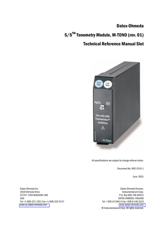
Front panel of S/5 Tonometry Module, M-TONO... 1
Figure 2
Absorbance of CO2 ...3
Figure 3
Gas sampling system layout ... 4
Figure 4
CO2 sensor... 5
Figure 5
Signal processing of the module ... 6
Figure 6
Signal and control logic ... 6
Figure 7
Exploded view of S/5 Tonometry Module, M-TONO ...27
TABLE OF TABLES Table 1
Module bus connector... 7
Table 2
Module general status ...17
Table 3
Module hardware status ...18
Table 4
Module keyboard status ...18
Table 5
Module general error status ...18
Table 6
Module pneumatics error status...19
Table 7
Module hardware error status...19
Table 8
Description of system test...22
Table 9
HEX to binary conversion...35
ii Document No. 800 1010-1
S/5 Tonometry Module, M-TONO
INTRODUCTION This slot provides information for maintenance and service of the Datex-Ohmeda S/5 Tonometry Module, M-TONO. Please see also related Technical Reference Manual for information related to system e.g. related documentation, conventions used, symbols on equipment, safety precautions, system description, system installation, interfacing, functional check and planned maintenance. The S/5 Tonometry Module is single width plug-in module and is designed for use with the S/5 monitors. The module provides gastric tonometry measurement, i.e. it measures the gastrointestinal CO2 concentration, PgCO2. The Tonometry Module contains the CO2 gas concentration sensor and a gas sampling system to move gas between the patient’s gastrointestinal tract and the sensors. The patient is connected to TM the module with a Tonometrics Catheter, which is inserted into the gastrointestinal tract. A sample is taken at regular intervals to determine the CO2 concentration of the gas.
1
PgCO 2
Use only with Tonometrics™ catheters
Figure 1 (1)
Front panel of S/5 Tonometry Module, M-TONO
Direct module keys: Start Stop Lab. Data
(2)
2
Starts/Stops the PgCO2 measurement cycle. Takes you to Lab Data menu to enter the blood gas values.
Connector for the Tonometrics Catheter
NOTE: The S/5 Tonometry Module, M-TONO functions only with monitor software of level 99 or newer.
1 Document No. 800 1010-1
Datex-Ohmeda S/5 monitors
1
SPECIFICATIONS
1.1 General specifications Module size, W × D × H Module weight
37 × 190 × 112 mm, 1.5 × 7.5 × 4.4 in 0.5 kg /1.1 lbs
Operating temperature Storage temperature
+10...+40 °C -25...+70 °C
Atmospheric pressure
666...1060 hPa (67...106 kPa/500...800 mmHg/666...1060 mbar)
Humidity
10...90 % non-condensing
Power consumption
0.7 W Prms, 9.0 W momentary
Protection against electrical shock
Type BF (IEC-60601-1) defibrillator-proof protection against electric shock
1.2 Parameter specifications Measurement interval is 10 minutes.
1.2.1 PgCO2 Measurement range
0...30 kPa (0...228 mmHg)
1
Accuracy in range 0...15 kPa (0...113 mmHg) in range 15...30 kPa (113...228 mmHg)
±(0.5 kPa +5 % of reading) ±(4 mmHg +5 % of reading) 1.5 kPa ±15 % of reading 12 mmHg ±15 % of reading
Accuracy specifications apply in normal conditions: Measurement is done at least 30 minutes after catheter initialization and calibration is checked within 2 weeks. Ambient temperature 10...40 °C, within ±5 °C of calibration Ambient pressure 500...800 mmHg, ±50 mmHg of calibration Ambient humidity 10...90 %RH, ±20 %RH of calibration
1 These specifications only apply when TONO-8F, TONO-14F, TONO-16F, TONO-18F catheters with 13 mm biofilter are used.
2 Document No. 800 1010-1
S/5 Tonometry Module, M-TONO
2
FUNCTIONAL DESCRIPTION
2.1 Measurement principle 2.1.1 CO2 measurement The CO2 sensor measurement is based on the infrared (IR) absorption technique. CO2 molecules absorb IR-light, that has a certain wave length (4.26 µm). This wavelength is selected from the incoming IR-light with a special optical bandpass filter. The IR-light passed through the measurement chamber and the filter and the signal is then detected with a thermopile. The calculation of CO2 concentration needs also the determination of the signal level, when there is no CO2 in the measured gas. This procedure is the zeroing of the sensor. The zeroing is done with room air and it is always done before measuring the sample gas.
Absorbance (arbitrary units)
The CO2 and zeroing gas measurements are done by pulsing the IR-lamp 3 times (lamp is on 2 seconds and off 2 seconds) and by measuring the thermopile signal during pulsing. The CO2 concentration is defined then from these signals. In the definition of CO2 partial pressure (PgCO2), the influence of sensor temperature, measurement pressure, catheter pressure, gas mixing in tubings and the drop in water vapour pressure on the measurement result are compensated.
CO2
Filter 4.0
4.5 Wavelength (µm)
Figure 2
Absorbance of CO2
3 Document No. 800 1010-1
Datex-Ohmeda S/5 monitors
2.2 Main components The tonometry module consist of: •
gas sampling system
•
CO2 measuring unit
•
CPU board.
2.2.1 Gas sampling system Valve unit room air inlet filter catheter pressure transducer zero valve
Pump unit
P Tube unit CO2 sensor
to catheter connector
= PVC tube = PVC+NafionTM tube
Figure 3
pump pump valve pressure transducer membrane P pump
M
linear stepper motor
room air inlet
Gas sampling system layout
The tonometry measurement is done with regular intervals of 10 minutes. The measurement cycle starts with CO2 sensor zeroing. Zeroing means flushing the gas measurement chamber with room air and measuring the signal level of IR-light passed through the room air. Straight after zeroing the sensor, sample gas is aspirated from the tonometry catheter and the IR-signal passed through the sample gas is measured. The actual CO2 concentration is determined from the measured zero signal and the CO2 signal. After determining the catheter gas CO2 concentration it is made sure that the catheter is empty by sucking vacuum in the catheter. After generating the vacuum, tubing system is equilibrated close to the ambient pressure by switching the pump valve on and off. Filling of the catheter is thus done always with the same amount of gas. The catheter is refilled with measured sample gas.
Catheter pressure transducer The catheter pressure transducer measures absolute catheter pressure.
Zero valve The valve is normally open to the room air. When sample gas is measured from the catheter, zero valve will be active.
Sensor After the zero valve the gas passes through CO2 sensor. 4 Document No. 800 1010-1
S/5 Tonometry Module, M-TONO
NafionTM tube 1) A nafion tube is used between the CO2 sensor and tube unit to balance the sample gas humidity with that of ambient air. The CO2 sensor measures humid gas and Nafion tube prevents humidity increasing in the tubes.
Tube unit Tube unit is used between the nafion tube and pump unit to store the sample gas.
Pump valve The valve is normally open to the room air. When CO2 consentration is measured from the sample gas or from the room air, pump valve will be active.
Pump pressure transducer The working pressure transducer measures absolute pump pressure. It is used for catheter empty message, catheter leakage message and unable to fill catheter message.
Membrane pump and linear stepper motor The gas sampling pump is a membrane pump that is run by a linear stepper motor. Sample volume is 4 ml.
2.2.2 CO2 sensor Temp sensor
CO2 sensor board
IR Lamp
Sample chamber I
Temp CO2
Optical Thermopile detectors filter
To CPU board
EEPROM
Sample gas out
Figure 4
Sample gas in
CO2 sensor
The CO2 sensor is a non dispersive infrared analyzer, measuring absorption of the gas sample at CO2 infrared wavelength, which is selected using optical narrow band filter. The IR lamp is a 500 mW filament, surrounded by thermal isolation. There is a hole in the isolation, passing the radiation to a conical measuring chamber with 3 mm length. The CO2 sensor contains own preamplifier board, which amplifies the thermopile signal. The preamplifier board also contains EEPROMs that store calibration data of CO2 sensor. The Temp sensor measures the temperature of the CO2 unit and it is used for temparature compensation. 1)
Nafion is a trademark of Perma Pure Inc.
5 Document No. 800 1010-1
Datex-Ohmeda S/5 monitors
2.2.3 CPU board The CPU board contains the processor, memories and AD-converter that are common to the whole module. The CPU board also contains preamplifiers of pressure sensors and drivers for valves, linear stepper motor and lamp. The module is connected to the module bus through an RS-485 serial channel. The CO2 sensor preamplifier board contains the EEPROM, preamplifier of IR thermopile sensors and temp sensor. CO2 preamplifier board
CPU board
IR Thermopile Sensor
Temp Sensor
EEPROM
A/D 12 bit
Pump unit
RS-484 driver
Pump press
CPU H8/3048
Pump valve Linear stepper motor
Stepper motor control
Zero unit Cath press Zero valve
Lamp unit Lamp current control
Lamp
Figure 5
Signal processing of the module T u b e u n it
V a lv e u n it
c a th e te r p re s s u re
X 6 X 4
X 7
d a ta E E P R O M
2
te m p e ra tu re
C O
la m p c u r r e n t c o n tro l
z e r o v a lv e c o n tro l
M e m b ra n e k e y s
P u m p u n it
C O 2 s e n s o r
X 2 C P U b o a rd
p u m p p re s s u re
X 3
X 8
m o d u le b u s c o n n e c to r
Figure 6
6 Document No. 800 1010-1
Signal and control logic
p u m p v a lv e c o n tr o l m o to r c o n tro l
Module bus
EEPROM
S/5 Tonometry Module, M-TONO
2.3 Connectors and signals 13
1
25
14
Table 1
Module bus connector
Pin No.
I/O
Signal
1 2 3 4 5 6 7 8 9 10 11 12 13 14 15 16 17 18 19 20 21 22 23 24 25
I I I I I/O I/O
RESET RS485 -15 VDC (not used) +15 VDIRTY +15VDC -DATA RS485 DATA RS485 Ground and Shield -RESET RS485 n/c n/c n/c n/c Ground and Shield +24/+32 VDIRTY Depends on power supply (not used) Ground DIRTY n/c n/c n/c n/c GASFR (not used) CTSD (not used) TXDD (not used) RXDD (not used) +5 VDC +5 VDC
I
I I
I I I O I I
7 Document No. 800 1010-1
Datex-Ohmeda S/5 monitors
3
SERVICE PROCEDURES
3.1 General service information Field service of the Tonometry module is limited to replacing faulty tubing or mechanical parts. Datex-Ohmeda is always available for service advice. Please provide the unit serial number, full type designation, and a detailed description of the fault.
CAUTION
Only trained personnel with appropriate equipment should perform the tests and repairs outlined in this section. Unauthorized service may void warranty of the unit.
CAUTION
The module electronics can only be repaired and calibrated at the factory.
3.1.1 CO2 sensor CAUTION
The CO2 sensor can only be repaired at the factory. Attempts to repair the sensor elsewhere will adversely affect operation of the sensor. The information provided is for reference only.
3.1.2 Factory calibration data CAUTION
If there is any fault in the CPU board, pump unit, valve unit or CO2 sensor, the module should be sent to the factory for repair. The CPU board contains calibration data for the pressure transducers in the pump unit and valve unit. The CO2 sensor preamplifier board contains calibration data for the sensor itself and for gas measurement electronics on the CPU board.
3.1.3 Serviceable or exchangeable parts •
nafion tube
•
other tubings
•
tube unit
•
mechanical parts
NOTE: After any component replacement see chapter Adjustments and calibrations.
8 Document No. 800 1010-1
S/5 Tonometry Module, M-TONO
3.2 Service check These instructions include complete procedures for a service check. The service check is recommended to be performed after any service repair. However, the service check procedures can also be used for determining possible failures. The procedures should be performed in ascending order. The instructions include a check form, APPENDIX A, which should be filled in when performing the procedures. The mark
? in the instructions means that the check list should be signed after performing the
procedure.
The procedures are designed for monitors with S/5 monitor software of revision 01. However, most of the procedures also apply to monitors, which contain some other monitor software type/revision.
3.2.1 Recommended tools Tool
Order No.
Screwdriver
-
Pressure manometer
-
Silicon tube
73373
Calibration gas Calibration gas regulator Calibration sampling line
755580 755534 733251
Air pressure gauge
-
Notes
Available in meters.
Luer plug TonometricsTM catheter See order numbers for accessories in the Patient Monitor Supplies and Accessories catalogue.
3.2.2 Recommended parts Part
Order No.
Special tube, 300 mm
733382
Notes
9 Document No. 800 1010-1
Datex-Ohmeda S/5 monitors Detach the module box by removing the two screws from the back of the module. Be careful with loose latch and spring pin for locking. 1.
Check internal parts: −
all screws are tightened properly
−
all cables are connected properly
−
tubes are not pinched and there are no sharp bends on them
−
all tubes are connected properly
? 2.
Check external parts: −
the front cover and the front panel sticker are intact
−
connectors are intact and are attached properly
−
the module box, latch and spring locking pin are intact
? 3.
Replace the nafion tube by new. NOTE: The nafion tube is recommended to be replaced annually.
? −
Reattach the module box and check that the latch moves properly.
−
Plug in the module. Check that it goes in smoothly and locks up properly
−
Turn the monitor on and wait until the normal monitoring screen appears.
−
Configure the monitor screen so that information regarding the tonometric measurement is shown, for example:
Monitor Setup - Screen 1 Setup - Digit Fields -Lower Field 4 - PgCO2 4.
Check that the module is recognized, i.e. the PgCO2 header with related information appears in the chosen digit field.
? 5.
Enter the service menu:
Monitor Setup - Install/Service (password 16-4-34) - Service (password 26-23-8) Record the information regarding the software of the tonometry module by selecting Scroll Vers and turning the ComWheel.
? 10 Document No. 800 1010-1
S/5 Tonometry Module, M-TONO 6.
Enter the tonometric module service menu: ...Parameters - More... - TONO Check that the ‘Timeouts’, ‘Bad checksums’ and ‘Bad c-s by mod’ values are not increasing faster than by 50 per second. Check that the memories of the module have passed the internal memory test, i.e. ‘RAM’, ‘ROM’ and ‘EEPROM’ all state OK. Check that the general error status, module pneumatics error status, module hardware error status and testbit status are zero.
?
7.
Check the front panel Start-Stop and Lab. Data membrane keys. Press each key for at least one second and check that the key being pressed is identified, i.e. the keyboard status changes.
?
8.
Perform the pressure sensor calibration (TONO - PressSensCal), see instructions from section 3.4.1 Pressure sensor calibration.
?
9.
Perform the system test (TONO - System Test). 1. Block the catheter port of the module airtight e.g. with a plug that is made for closing a syringe. 2. Select Start Test. 3. Wait until the automatic test procedure is over. The results are given in the data field and descriptions of the tested parts are listed in table 8, see section 5.4 System test. The test can be interrupted at any time by selecting Stop Test. NOTE: The system test takes about one minute to carry out. NOTE: Use a plug with very small volume to block the catheter port.
?
10.
Perform the gas calibration (TONO - Tonometry - PgCO2 Calibration).
11.
Connect the catheter to the tonometry module. Start tonometric measurement by pressing the Start-Stop key on the module. If measurement is turned on PgCO2 time bat replaces the Meas Off text. Check that the catheter fills up. Stop the measurement by pressing the Start-Stop key.
? ?
11 Document No. 800 1010-1
Datex-Ohmeda S/5 monitors 12.
Clean the module with suitable detergent.
?
Fill in all necessary documents.
3.3 Disassembly and reassembly Disassemble the tonometry module in the following way. See also the exploded view of the module. 1.
Remove two screws from the back of the module.
2.
Pull the module box slowly backwards and detach it from the main body.
Reassembling is essentially reversing what was described above.
CAUTION
When reassembling the module, make sure that the tubes and cables are not pinched between the boards and the cover.
3.3.1 Instructions after replacing tubings After replacing any part of the tubings: •
perform the System test
•
perform the PgCO2 calibration
3.4 Adjustments and calibrations 3.4.1 Pressure sensor calibration Before the procedure:
1.
2.
3. 12 Document No. 800 1010-1
−
Find out what the ambient pressure is at the moment in [mmHg] or [mbar].
−
Find a device with which you can apply a known pressure of about 100 mmHg to the catheter port. There are e.g. blood pressure gauges that will do. Make sure that it can be connected to a male luer connector.
The monitor prompts: ‘Make sure that catheter connector is open to room air and start calibration.’ −
Remove catheter, plug, pressure gauge or anything that is connected to catheter port of the module.
−
Select Start Calib
The monitor prompts: ‘Calib started. Make sure that catheter connector is open to room air.’ −
Remove catheter, plug, pressure gauge or anything that is connected to catheter port of the module, if not done already.
−
Wait a moment.
The monitor prompts ‘Adjust ambient pressure.’
S/5 Tonometry Module, M-TONO
4.
5.
6.
−
Turn ComWheel to match the highlighted pressure value (or the corresponding value in mbar to the right of the mmHg reading) to the known ambient pressure.
−
Press ComWheel.
The monitor prompts: ‘Pump approximately 100 mmHg pressure and adjust cal. press. to match.’ −
Connect the blood pressure gauge to the catheter port.
−
Pump in a pressure between 95 and 105 mmHg.
−
Turn ComWheel to match the highlighted pressure value to the applied pressure.
−
Press ComWheel.
The monitor prompts ‘Store or discard new sensor gains and offsets.’ −
Turn ComWheel to display YES if you want to store the calibration factors or NO if you do not want to store them.
−
Press ComWheel.
The monitor prompts ‘Calibration finished.’ Everything went OK and the calibration is finished. OR The monitor prompts: ‘Calibration pressure too close to ambient pressure.’ The applied pressure was too small and you have to redo the calibration.
3.4.2 System test 1.
Plug the catheter port of the module airtight e.g. with a plug that is made for closing a syringe.
2.
Select Start Test.
3.
Wait till the automatic test procedure is over. The results are given in the data field and descriptions of the tested parts are listed in table 8, see section System test.
The test can be interrupted at any time by selecting Stop Test. NOTE: The system test takes about one minute to carry out. NOTE: Use a plug with very small volume to block the catheter port.
3.4.3 PgCO2 calibration The gas calibration is performed in the Others - Tonometry or ...Service - Parameters - More... TONO - Tonometry submenu. 1.
Connect the calibration gas sampling line to the regulator and to the module’s catheter connector.
2.
Press the Others key on the monitor keyboard.
3.
Select Tonometry - PgCO2 Calibration.
13 Document No. 800 1010-1
Datex-Ohmeda S/5 monitors 4.
Wait until the text ‘Start feeding gas and press ComWheel. Feed gas until Adjust message is displayed’ appears. Open the regulator and start feeding gas. Press the ComWheel and continue feeding gas until the text ‘Adjust’ appears on the display.
5.
Check that the displayed values match the values on the calibration gas container. Adjust with the ComWheel if necessary.
6.
It is recommended to calibrate the airway gases at the same time.
14 Document No. 800 1010-1
S/5 Tonometry Module, M-TONO
4
TROUBLESHOOTING
4.1 Troubleshooting chart Trouble
Possible cause and treatment
Tonometry module HW error.
Module hardware error. Return the module to the factory for repair.
Tonometrics catheter empty.
There is no gas in the tonometry catheter. It will be filled automatically during the next measurement. Occlusion in the catheter, or leak in the catheter or connector in the module. Check catheter.
Tonometrics catheter leakage.
The tonometry catheter is disconnected, the tubes are leaking inside the module or the catheter is leaking. Ensure proper catheter connection and have the internal leak repaired.
Unable to fill tonometrics catheter.
Occlusion in the catheter or the balloon is squeezed. Check catheter.
4.2 Gas sampling system troubleshooting The faults which can occur in the sampling system are: leaks or blockages in the tubing, fault in pressure sensors, failure of the sampling pump or the magnetic valves. The system test should help in localizing the fault. Whenever suspecting the sampling system and always after having done any work on the sampling system check and if necessary adjust the pressure sensors.
CAUTION
The special internal sample tube is mechanically fragile. Sharp bends will cause leaks.
CAUTION
If there is any fault in the CPU board, pump unit, valve unit or CO2 sensor, the module should be sent to factory for repair. The CPU board contains calibration data for the pressure transducers in the pump unit and valve unit. NOTE: If any liquid has entered the module, contact Datex-Ohmeda Technical Services.
15 Document No. 800 1010-1
Datex-Ohmeda S/5 monitors
5
SERVICE MENU
1.
Press the Monitor Setup key.
2.
Select Install/Service (password: 16-4-34).
3.
Select Service (password: 26-23-8).
4.
Select Parameters - More... - TONO.
16 Document No. 800 1010-1
S/5 Tonometry Module, M-TONO
5.1 Tonometry service menu
Service Data Tonometry
A selection to enter the Tonometry setup menu.
PressSensCal
A selection to enter the module pressure sensor calibration menu.
System Test
A selection to enter the module system test.
CO2 Sensor
A selection to enter the module CO2 sensor menu.
Pneumatics
A selection to enter the module pneumatics menu.
AD
A selection to enter the module AD value display.
Record Data
A selection to print out the shown service data to the device defined in the ...Service - Record Data menu.
Previous Menu A selection to return to the previous menu.
TONO Statuses (HEX): See Appendix B; How to read HEX numbers. General
Module general status. See table 2 to see the detailed description of the message. Table 2 bit 0-5 bit 6 bit 7 bit 8 bit 9
Module general status Not used State error Communication failure Power failure Clock failure
17 Document No. 800 1010-1