Reference Manual
60 Pages
Preview
Page 1
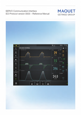
SERVO Communication Interface SCI Protocol version 0003 – Reference Manual
Notes
Reference Manual
SERVO Communication Interface
Table of Contents 1 INTRODUCTION ... 5 1.1 General information ... 5 1.2 Operation ... 5 1.3 Equipment combinations ... 5 1.4 Definitions and Acronyms... 6 1.4.1 Definitions ... 6 1.4.2 Common acronyms ... 6 1.5 Typographical conventions... 7 1.6 Protocol version/System version matrix ... 7 1.7 Compatibility ... 8 1.8 Disclaimer ... 8 2 PROTOCOL SPECIFICATION ... 9 2.1 Introduction ... 9 2.2 Communication Requirements - General ... 9 2.2.1 The RS-232 communication settings ... 9 2.2.2 Signal Handshake protocol... 9 2.2.3 Error handling ... 10 2.2.4 Performance requirements ... 11 2.2.5 Support for different SCI Protocol versions ... 11 2.2.6 Design/compatibility considerations for driver developers ... 11 2.3 Channels ... 12 2.3.1 Channel 0-99 – Real time curves ... 12 2.3.2 Channel 100-399 – Breath data ... 13 2.3.2.1 Switch Parameters for channel 100 - 399 ... 15 2.3.3 Channel 400-599 – Settings ... 16 2.3.3.1 Switch Parameters for channel 400 - 599 ... 19 2.3.4 Channel 600-799 – Alarm settings ... 24 2.3.5 Channel 800-999 – Alarms ... 25 2.4 Commands ... 27 2.4.1 Empty command ... 28 2.4.2 Escape ... 28 2.4.3 Read Acquired Data RADA ... 29 2.4.3.1 Curve Data ... 29 2.4.3.2 Breath Data ... 30 2.4.3.3 Settings Data ... 31 2.4.3.4 Alarm Settings Data ... 31 2.4.3.5 Alarm Data ... 31 2.4.4 Read Acquired Data Continuously RADC ... 32 2.4.5 Read Alarm Output RALO ... 34 2.4.6 Read Channel Configuration RCCO ... 34 2.4.7 Read CI Type RCTY... 35 2.4.8 Read Data Acquisition Definition RDAD... 35 2.4.9 Read Highest Protocol Version RHVE ... 36 2.4.10 Read Patient Info RPAI ... 36 2.4.11 Read Protocol Version RPVE ... 36 2.4.12 Read Serial Number RSEN ... 37 2.4.13 Read Sampling Time RSTI ... 37 2.4.14 Read Software Version RSWV... 37 2.4.15 Read Time RTIM ... 37 2.4.16 Read input character Timeout RTOU ... 38 2.4.17 Set Data Acquisition Definition SDAD ... 38 2.4.18 Set Protocol Version SPVE ... 39 2.4.19 Set Sampling Time SSMP ... 39 68 80 036_04
3
SERVO Communication Interface
Reference Manual
2.4.20 Set input character timeout STOU ... 39 2.5 Checksum calculation ... 40 2.5.1 General ... 40 2.5.2 Formula ... 40 2.5.3 Checksum transmission ... 40 2.5.4 Example ... 40 3 APPENDIX A – DISPLAY RANGE ... 41 3.1 Waveforms ... 41 3.2 Breath data ... 42 3.2.1 Switch parameters for channel 140 ... 44 3.2.2 Switch parameters for channel 141 ... 44 3.2.3 Switch parameters for channel 142 ... 44 3.3 Parameter settings ... 45 3.3.1 Switch parameters for channel 410 ... 49 3.3.2 Switch parameters for channel 413 ... 49 3.3.3 Switch parameters for channel 417 ... 50 3.3.4 Switch parameters for channel 423 ... 50 3.3.5 Switch parameters for channel 435 ... 50 3.3.6 Switch parameters for channel 442 ... 51 3.3.7 Switch parameters for channel 446 ... 51 3.3.8 Switch parameters for channel 449 ... 51 3.3.9 Switch parameters for channel 450 ... 51 3.4 Alarm limit settings ... 52 3.5 Alarm texts ... 53 4 REVISION HISTORY ... 55 4.1 Protocol version 0001 – Reference Manual revision 00 ... 55 4.2 Protocol version 0001 – Reference Manual revision 01 ... 55 4.3 Protocol version 0002 – Reference Manual revision 02 ... 55 4.4 Protocol version 0003 – Reference Manual revision 04 ... 57
4
68 80 036_04
Reference Manual
1
INTRODUCTION
1.1
General information
SERVO Communication Interface
The purpose of this Reference Manual is to describe the design of the SERVO Communication Interface (SCI) Protocol version 0003, introduced with SERVO-air System version 1.0. The SCI protocol is used in SERVO-U, SERVO-n and SERVO-air with protocol versions according to chapter 1.6. The manual provides information about commands and responses in using the SERVO Communication Interface (SCI). Throughout this Reference Manual, SERVO represents the SERVO-U/SERVO-n and SERVO-air Ventilator System. The mapping between SCI and the data displayed on the SERVO User Interface is described in chapter 3 Appendix A – Display range. The SERVO Communication Interface (SCI) described herein interfaces an external equipment via an RS-232C serial interface. This specification states the requirements for the communication protocol between the SCI and an external equipment. This Reference Manual is intended for programmers only. For support, please contact [email protected]. Updated revisions of the Reference Manual will be published when new SCI Protocol versions are released. It is recommended to use the latest version of the Reference Manual, check on www.maquet.com for updates. The SERVO Communication Interface is an integrated part of the SERVO Ventilator System. In addition to the information given here, always pay attention to the information in the User’s Manual. The SERVO Communication Interface must not be used as a component in a remote alarm system. MAQUET has no responsibility for the safe operation of the equipment if service or repair is done by a nonprofessional or by persons who are not employed by or authorized by MAQUET. We recommend that service be done as part of a service contract with MAQUET.
1.2
Operation
Due to factors not controlled by MAQUET, the correctness of processed metering values obtained from the SERVO Communication Interface cannot be guaranteed. MAQUET disclaims all responsibility for the correctness of signals processed by external equipment. If there should be any deviation between information shown on SERVO and that shown by external equipments, the parameters shown on SERVO shall be considered the primary source for information. It is therefore recommended that the data is verified against actual preset and measured values of SERVO. Data obtained from the SERVO Communication Interface, which have been processed in external equipments, must not be used as a substitute for therapeutic or diagnostic decisions. Such decisions can be made only by staff with medical expertise, according to established and accepted practice.
1.3
Equipment combinations
Only components, accessories, supplies and external equipment recommended by MAQUET should be used with the system. Use of any other components, accessories, supplies and external equipment may cause degraded system performance and safety. Before starting to use the system with connected external equipment, ensure that the whole combination complies with the international standard IEC 60601-1-1 and the requirements of the local authorities.
68 80 036_04
5
SERVO Communication Interface
1.4
Definitions and Acronyms
1.4.1
Definitions
Reference Manual
Alarm
Alarm data is alarm information generated by the ventilator.
Alarm settings
Alarm settings data represent alarm limit settings.
Breath
Breath data is updated once a breath.
Curve
Curve data changes very often and is typically used to draw real time graphs. It is sampled periodically.
Control Modes
PC, VC, PRVC, NIV-PC, Bi-Vent/APRV.
Parameter
SCI command parameter, i.e. extra information needed to define the semantics of a given SCI command message. For instance, for a read command the parameter designates the data to read.
Preset cycle time
The time equal to 1/CMV freq. (BPM).
Settings
Settings data represent panel settings.
Support Modes
VS, PS, NIV-PS, NAVA, NIV-NAVA.
Technical
Technical information, e.g. module version, configuration etc.
1.4.2
Common acronyms
AD
Alarm data
Bi-Vent/APRV
Pressure controlled ventilation mode with the possibility of spontaneous breathing/pressure support on two different pressure levels. APRV: Airway Pressure Release Ventilation.
BPM
Breaths per minute.
BR
Breath data.
Breath cycle T
See SIMV Cycle.
CMV
Continuous Mandatory Ventilation.
CPAP
Continuous Positive Airway Pressure.
CU
Curve data.
Edi
Electrical activity of the diaphragm.
Exp. time
Expiration time.
Insp. time
Inspiration time.
N/A
Not applicable.
NAVA
Neurally Adjusted Ventilatory Assist.
NIV
Non Invasive Ventilation.
NIV-NAVA
Non Invasive – NAVA.
NIV-PC
Non Invasive – Pressure Control.
NIV-PS
Non Invasive – Pressure Support.
PEEP
Positive End Expiratory Pressure.
PC
Pressure Control.
PS
Pressure Support.
PRVC
Pressure Regulated Volume Control.
6
68 80 036_04
Reference Manual
SERVO Communication Interface
SCI
Servo Communication Interface.
SD
Settings/Alarm settings data.
SIMV Cycle
The time between the mandatory breaths in an SIMV mode.
SIMV (PC)
SIMV (Pressure Control). Synchronized Intermittent Mandatory Ventilation with Pressure Control (PC) mandatory breaths.
SIMV (PRVC)
SIMV (Pressure Regulated Volume Control). Synchronized Intermittent Mandatory Ventilation with Pressure Regulated Volume Control (PRVC) mandatory breaths.
SIMV Rate
A Ventilation Setting used to set the mandatory breathing rate in SIMV mode.
SIMV (VC)
SIMV (Volume Control). Synchronized Intermittent Mandatory Ventilation with Volume Control (VC) mandatory breaths.
VC
Volume Control.
VS
Volume Support.
1.5
Typographical conventions
When reading this specification, note that: <>
encloses abbreviations, numerical value, etc.
NN16
means hexadecimal value
[]
encloses parameters that are not necessary to use
{}
encloses the set of valid data
...
indicates sequence
1.6
Protocol version/System version matrix
The SCI protocol is used in SERVO-U, SERVO-n and SERVO-air with Protocol/System versions according to table below: Protocol version Product SERVO-U/SERVO-n SERVO-air
System version
0001
0002
1.0
X
1.1
Note 1
X
1.0
Note 1
Note 1
0003
X
Note 1: Older protocol versions are emulated by the software.
68 80 036_04
7
SERVO Communication Interface
1.7
Reference Manual
Compatibility
To consider when writing a SCI driver: The SCI Protocol is designed to be backwards compatible. However, even if the SCI driver is not updated with new functionality, it is still important to make sure that the SCI driver works with the new SERVO System version. At SERVO startup, the functionality from SCI Protocol version 0001 is selected by default. Command SPVE must be used to set a later protocol version. New or modified data channels are available after selecting higher SCI Protocol versions with the command SPVE. The protocol version is selectable from SCI Protocol version 0001 to highest for the current SERVO System version, read by the RHVE command. See chapter 2.2.5 Support for different SCI Protocol versions. The output from the command RSWV will be updated when a new SERVO System version is released. The output from the command RHVE will be updated when a new SCI Protocol version is released. After sending a command to SCI, wait for the response or abort the command with ESC.
1.8
Disclaimer
The device may be pending regulatory approvals to be marketed in your country. Contact your MAQUET representative for more information. Caution: Federal (US) law restricts sale of this device to, or on the order of, a physician.
8
68 80 036_04
Reference Manual
SERVO Communication Interface
2
PROTOCOL SPECIFICATION
2.1
Introduction
The SCI interfaces an external equipment via an RS-232C serial interface. The information transfer between the SCI and the external equipment is performed via a serial communication line. The external equipment acts as the master and transmits commands to the SCI in order to retrieve information. Curve data, breath data, settings data, alarm settings data, alarm data and technical information may be retrieved from the ventilator through SCI.
2.2
Communication Requirements - General
2.2.1 The RS-232 communication settings The serial interface is according to RS-232C and fulfills the following requirements: Baud rate: 38 400 Data length: 8 bits Stop bits: 1 bit Parity: Even Data format: Binary Handshake: None
2.2.2 Signal Handshake protocol The following control characters are used, in order to control the data flow from the SCI: <EOT>= 0416
End of transmission. General character to be used to define the end of an instruction or end of an ASCII response from the SCI. Note: An ASCII string is not null terminated.
<ESC> = 1B16
Issued by the computer to interrupt the data transfer from the SCI. Upon reception of ESC, SCI aborts transmission and any running command, e.g. RADC, and sends the error message “Command aborted by ESC”. Transmission is restarted upon reception of the next valid command.
<CHK>
Calculated checksum. Checksum is sent either as one byte or two bytes; one byte in binary answer or two bytes in ASCII answer. The checksum calculation is defined in chapter 2.5.
68 80 036_04
9
SERVO Communication Interface
Reference Manual
2.2.3 Error handling The SCI validates input data in order to detect errors. In case of error the SCI replies with an error message depending on the type of error and the command type, i.e. ASCII or binary. The following error messages apply to ASCII response: Error
Error name
Error code (ASCII)
Error message (ASCII)
Not a valid command
ER10
ER10
ER10<CHK><EOT>
Syntax error, e.g. too many, too few parameters, or same parameter twice
ER11
ER11
ER11<CHK><EOT>
Parameter value out of range or parameter not supported by the ventilator
ER12
ER12
ER12<CHK><EOT>
SCI not configured
N/A
N/A
N/A
Ventilator is in Standby mode
N/A
N/A
N/A
Checksum error
ER18
ER18
ER18<CHK><EOT>
Output buffer full
ER19
ER19
ER19<CHK><EOT>
Command aborted by ESC
ER20
ER20
ER20<CHK><EOT>
The ASCII error message consists of the error code followed by the checksum and end of transmission: <error code><CHK><EOT> The following error messages apply to Binary response: Error
Error name
Error code (Binary)
Error message (Binary)
Not a valid command
N/A
N/A
N/A
Syntax error, e.g. too many, too few parameters, or same parameter twice
BER11
0B16
E00B7F16<CHK>
Parameter value out of range or parameter not supported by the ventilator
BER12
0C16
E00C7F16<CHK>
SCI not configured
BER16
1016
E0107F16<CHK>
Ventilator is in Standby mode
BER17
1116
E0117F16<CHK>
Checksum error
N/A
N/A
N/A
Output buffer full
BER19
1316
E0137F16<CHK>
Command aborted by ESC
BER20
1416
E0147F16<CHK>
Note that the binary error code is preceded by the error flag (E016) and followed by the end flag (7F16) and the checksum in a binary error response: <error_flag><error code><end_flag><CHK> Note that since all SCI command messages are ASCII messages, the error “Not a valid command” is always returned as an ASCII response message. This is the reason why the error “Not a valid command” is not applicable as a binary response message. Note that “Checksum error” is always returned as an ASCII response, since it is not possible to determine what command generated the error. If it is not possible to calculate or retrieve data designated by a command parameter within the SCI, a "Missing value, which is 7EFF16 for Binary", is transferred.
10
68 80 036_04
Reference Manual
SERVO Communication Interface
2.2.4 Performance requirements The SCI needs to receive any character within set timeout, otherwise the previous characters are ignored. See command RTOU, chapter 2.4.16 and command STOU, chapter 2.4.20 for more information. SCI sends the first character of the response to all commands within 500 ms, unless otherwise stated in the description of each specific command.
2.2.5 Support for different SCI Protocol versions The SCI provides a mechanism for selecting between different protocol versions. The following commands are used: Read Highest Protocol Version, RHVE: Requests information about the highest available SCI Protocol version for the current System SW version. Read Protocol Version, RPVE: Requests information about the SCI Protocol version currently in use. Set Protocol Version, SPVE: Configures SCI to use a specific Protocol version. The lowest selectable protocol version is SCI Protocol version 0001. This protocol version is selected at the startup, and when the RCTY command is received. The difference between protocol versions are that: Existing channels can be deleted New channels can be added The configuration, or switch parameters, for existing channels can be changed New commands can be added.
2.2.6 Design/compatibility considerations for driver developers Command RCCO, see chapter 2.4.6, shall be used to get the list with actual channels and corresponding configurations.
68 80 036_04
11
SERVO Communication Interface
2.3
Reference Manual
Channels
A SERVO parameter corresponds to a channel number in the SCI protocol. When a SERVO parameter shall be read with the command RADC or RADA, the command SDAD is used to add a channel number to the list of activated channels. The following table defines channels and corresponding SERVO parameters: Channels 00 – 99:
Reserved for the real time curves.
Channels 100 – 399:
Reserved for the breath data.
Channels 400 – 599:
Reserved for the settings.
Channels 600 – 799:
Reserved for the alarm settings.
Channels 800 – 999:
Reserved for the alarms.
The list with activated SCI channels is cleared at startup, with the commands ”Read CI Type” (RCTY) and “Set Protocol Version“ (SPVE).
Ch No
Parameter Name
0001
0002
0003
2.3.1 Channel 0-99 – Real time curves Channels used for real time curves. The configuration, i.e. actual scale factors, is received via the command Read Channel Configuration (RCCO). For more information about the configuration see the description of the command RCCO. SCI supports curve channels according to the following table: Configuration (gain, offset, unit, type)
0
Airway Flow
X
X
X
+2500E-004, +4000E+000, 02, CU
1
Airway Pressure
X
X
X
+1000E-004, +2000E-001, 04, CU
2
Volume
X
X
X
+2000E-004, +0000E+000, 01, CU
3
Edi
X
X
X
+1000E-005, +0000E+000, 19, CU
4
CO2 concentration (%)
X
X
X
+1000E-004, +0000E+000, 07, CU
5
CO2 concentration (mmHg)
X
X
X
+1000E-004, +0000E+000, 10, CU
6
CO2 concentration (kPa)
X
X
X
+1000E-004, +0000E+000, 11, CU
7-99
Not defined
12
Available in Protocol version:
68 80 036_04
Reference Manual
SERVO Communication Interface
Ch No
Parameter Name Available in Protocol version:
0001
0002
0003
2.3.2 Channel 100-399 – Breath data Channels used for breath data. The configuration, i.e. actual scale factors, is received via the command Read Channel Configuration (RCCO). For more information about the configuration see the description of the command RCCO. Most breath data will be based on Y-piece data when Y-piece measurement is active. SCI supports breath channels according to the following table: Configuration (gain, offset, unit, type)
100
Measured breath frequency
X
X
X
+1000E-004, +0000E+000, 06, BR
101
Exp. tidal volume
X
X
X
+2000E-004, +0000E+000, 01, BR
102
Insp. Tidal volume
X
X
X
+2000E-004, +0000E+000, 01, BR
103
Insp. Minute volume
X
X
X
+1000E-005, +0000E+000, 08, BR
104
Exp. minute volume
X
X
X
+1000E-005, +0000E+000, 08, BR
105
Peak pressure
X
X
X
+1000E-004, +2000E-001, 04, BR
106
Mean airway pressure
X
X
X
+1000E-004, +2000E-001, 04, BR
107
Pause pressure
X
X
X
+1000E-004, +2000E-001, 04, BR
108
End exp. pressure
X
X
X
+1000E-004, +2000E-001, 04, BR
109
O2 concentration
X
X
X
+1000E-004, +0000E+000, 07, BR
110
Barometric pressure
X
X
X
+1000E-003, +0000E+000, 12, BR
111
Gas supply pressure, Air
X
X
X
+1000E-003, +0000E+000, 12, BR
112
Gas supply pressure, O2
X
X
X
+1000E-003, +0000E+000, 12, BR
113
CO2 tidal production
X
X
X
+1000E-004, +0000E+000, 01, BR
114
End tidal CO2 concentration (%)
X
X
X
+1000E-004, +0000E+000, 07, BR
115
End tidal CO2 concentration (mmHg)
X
X
+1000E-004, +0000E+000, 10, BR X
+1000E-003, +0000E+000, 10, BR
116
End tidal CO2 concentration (kPa)
X
X
X
+1000E-004, +0000E+000, 11, BR
117
CO2 minute production
X
X
X
+1000E-003, +0000E+000, 03, BR
118
Exp. Resistance
X
X
X
+1000E-004, +0000E+000, 09, BR
119
Static Compliance
X
X
X
+1000E-004, +0000E+000, 05, BR
120
End exp. Flow
X
X
X
+2500E-004, +4000E+000, 02, BR
121
Insp. Resistance
X
X
X
+1000E-004, +0000E+000, 09, BR
122
I:E Ratio (Note 1)
X
X
X
+1000E-005, +0000E+000, 20, BR
123
Ti (Insufflation time)
X
X
X
+1000E-005, +0000E+000, 14, BR
124
Fixed value = 7EFF16 (Note 2)
X
X
X
+1000E-004, +0000E+000, 05, BR
125
Dynamic Characteristics
X
X
X
+1000E-004, +0000E+000, 05, BR
126
Leakage fraction
X
X
X
+1000E-004, +0000E+000, 07, BR
127
Elastance
X
X
X
+1000E-004, +0000E+000, 16, BR
128
Ti/Ttot
X
X
X
+1000E-007, +0000E+000, 20, BR
129
Total PEEP
X
X
X
+1000E-004, +2000E-001, 04, BR
130
Spontaneous Breath frequency
X
X
X
+1000E-004, +0000E+000, 06, BR
68 80 036_04
13
Ch No
Parameter Name Available in Protocol version:
0002
0003
Reference Manual
0001
SERVO Communication Interface
Configuration (gain, offset, unit, type)
131
MVe spont
X
X
X
+1000E-005, +0000E+000, 08, BR
132
MVe spont/MVe in Bi-Vent/APRV
X
X
X
+1000E-007, +0000E+000, 20, BR
133
Time constant
X
X
X
+1000E-005, +0000E+000,14, BR
134
Work of Breathing, Ventilator
X
X
X
+1000E-005, +0000E+000, 18, BR
135
Work of Breathing, Patient
X
X
X
+1000E-005, +0000E+000, 18, BR
136
CPAP
X
X
X
+1000E-004, +2000E-001, 04, BR
137
P01
X
X
X
+1000E-004, +2000E-001, 04, BR
138
Edi peak
X
X
X
+1000E-005, +0000E+000, 19, BR
139
Edi min
X
X
X
+1000E-005, +0000E+000, 19, BR
140
Insp. Trigger cause
X
X
X
-, -, -, BR
141
Cycle off cause
X
X
X
-, -, -, BR
142
Exp. Trigger cause
X
X
X
-, -, -, BR
143
Shallow Breathing Index (SBI)
X
X
X
+1000E-003, +0000E+000, 22, BR
144
Remaining Nebulization time
X
X
X
+1000E-004, +0000E+000, 23, BR
145
VTe/Predicted Body Weight
X
X
X
+1000E-004, +0000E+000, 25, BR
146399
Not defined
Note 1: SCI sends I:E Ratio in the format “value:1”. This format is also used by the User Interface as long as “value” ≥1. Example: SCI value 2.0 is displayed as 2.0:1. With a “value” <1 the I:E Ratio is displayed in the format “1:1/value”. Example: SCI value 0.5 is displayed as 1:2.0. Note 2: Channel supported for backward compatibility.
14
68 80 036_04
Reference Manual
SERVO Communication Interface
2.3.2.1 Switch Parameters for channel 100 - 399 Ch No
Switch Parameters
140
Insp. Trigger cause Value: Trig cause undefined ... = 000116 Trig by CMV rate ... = 000216 Flow Trig ... = 000316 Pressure Trig ... = 000416 Edi Trig ... = 000516 Time to give a mandatory breath ... = 000616 “Start breath” button pressed ... = 000716 Reserved for future use ... = 000816-7EFE16 Undefined ... = 7EFF16
141
Cycle off cause Value: Cycle off cause undefined ... = 000116 Cycle off due to Edi drop to 70% of its peak value ... = 000216 Cycle off due to pressure criteria ... = 000316 Cycle off due to a too big TV ... = 000416 Cycle off due to an inspiratory time limitation ... = 000516 Cycle off due to flow level below set cycle off criteria... = 000616 Reserved for future use ... = 000716-7EFE16 Undefined ... = 7EFF16
142
Exp. Trigger cause Value: Trig cause undefined ... = 000116 A cycle off criteria is reached ... = 000216 Pressure limit reached (Safety limit) ... = 000316 Pressure limit reached (UPL) ... = 000416 Reserved for future use ... = 000516-7EFE16 Undefined ... = 7EFF16
68 80 036_04
15
SERVO Communication Interface
Reference Manual
Ch No
Parameter Name Available in Protocol version:
0001
0002
0003
2.3.3 Channel 400-599 – Settings Channels used for settings. The configuration, i.e. actual scale factors, is received via the command Read Channel Configuration (RCCO). For more information about the configuration see the description of the command RCCO. SCI supports settings channels according to the following table: Configuration (gain, offset, unit, type)
400
RR (in Control modes)
X
X
X
+1000E-004, +0000E+000, 06, SD
401
Leakage compensation Status
X
X
X
-, -, -, SD
402
T pause (%)
X
X
X
+1000E-004, +0000E+000, 07, SD
403
SIMV rate
X
X
X
+1000E-004, +0000E+000, 06, SD
404
Tinsp. rise (%)
X
X
X
+1000E-004, +0000E+000, 07, SD
405
Minute volume
X
X
X
+1000E-005, +0000E+000, 08, SD
406
PC above PEEP (Pressure Control Level above PEEP)
X
X
X
+1000E-004, +0000E+000, 04, SD
407
PS above PEEP (Pressure Support Level above PEEP)
X
X
X
+1000E-004, +0000E+000, 04, SD
408
PEEP
X
X
X
+1000E-004, +0000E+000, 04, SD
409
Patient range selection
X
X
X
-, -, -, SD
410
Ventilation Mode
X
X
X
-, -, -, SD
411
Status of current user request (e.g. Inspiratory Hold). - INSPIRATORY HOLD - EXPIRATORY HOLD - O2 BOOST - MANUAL BREATH
X
X
X
-, -, -, SD
412
CPAP
X
X
X
+1000E-004, +0000E+000, 04, SD
413
Alarm mute/pre-mute Status
X
X
X
-, -, -, SD
414
O2 conc.
X
X
X
+1000E-004, +0000E+000, 07, SD
415
Trigger sensitivity (Pressure trigger sensitivity level )
X
X
X
-1000E-004, +0000E+000, 04, SD
416
Trigger sensitivity (Flow trigger sensitivity level)
X
X
X
+1000E-005, +0000E+000, 08, SD
417
Language
X
X
X
-, -, -, SD
418
Displayed CO2 Unit
X
X
X
-, -, -, SD
419
I:E (Note 1)
X
X
X
+1000E-005, +0000E+000, 20, SD
420
Tidal volume
X
X
X
+2000E-004, +0000E+000, 01, SD
421
Backup RR (in Support modes)
X
X
X
+1000E-004, +0000E+000, 06, SD
16
68 80 036_04
Ch No
Parameter Name Available in Protocol version:
0002
0003
SERVO Communication Interface
0001
Reference Manual
Configuration (gain, offset, unit, type)
422
Backup Ti (s) (in Support modes)
X
X
X
+1000E-005, +0000E+000, 14, SD
423
NIV Program Status
X
X
X
-, -, -, SD
424
Phigh (High-pressure level in Bi-Vent/APRV)
X
X
X
+1000E-004, +0000E+000, 04, SD
425
Thigh (High pressure level time in Bi-Vent/APRV)
X
X
X
+1000E-005, +0000E+000, 14, SD
426
TPEEP (Low pressure level, PEEP, time in Bi-Vent/APRV)
X
X
X
+1000E-005, +0000E+000, 14, SD
427
PS above Phigh (Pressure Support level above Phigh in Bi-Vent/APRV)
X
X
X
+1000E-004, +0000E+000, 04, SD
428
PS above PEEP (Pressure Support level above PEEP in Bi-Vent/APRV)
X
X
X
+1000E-004, +0000E+000, 04, SD
429
Ti (s) (Inspiration Time in Seconds)
X
X
X
+1000E-005, +0000E+000, 14, SD
430
T pause (s) (Pause Time in Seconds)
X
X
X
+1000E-005, +0000E+000, 14, SD
431
Tinsp. rise (s) (Insp. Rise time in Seconds)
X
X
X
+1000E-005, +0000E+000, 14, SD
432
Breath cycle T (in SIMV modes)
X
X
X
+1000E-005, +0000E+000, 14, SD
433
Backup PC above PEEP (in Support modes)
X
X
X
+1000E-004, +0000E+000, 04, SD
434
Flow (Inspiration Peak Flow)
X
X
X
+1000E-006, +0000E+000, 15, SD
435
Suction Support Status
X
X
X
-, -, -, SD
436
End inspiration (Cycle off Fraction Level)
X
X
X
+1000E-004, +0000E+000, 07, SD
437
Circuit compliance compensation Status
X
X
X
-, -, -, SD
438
Max. apnea time (Trigger timeout in Automode)
X
X
X
+1000E-005, +0000E+000, 14, SD
439
Y-piece measurement Status
X
X
X
-, -, -, SD
440
Edi trigger
X
X
X
+1000E-005, +0000E+000, 19, SD
441
NAVA level
X
X
X
+1000E-005, +0000E+000, 21, SD
442
Gas Type Setting
X
X
X
-,-,-,SD
443
Backup Tidal volume (in Support modes)
X
X
X
+2000E-004, +0000E+000, 01, SD
68 80 036_04
17
Ch No
Parameter Name Available in Protocol version:
0002
0003
Reference Manual
0001
SERVO Communication Interface
Configuration (gain, offset, unit, type)
444
Backup I:E (in Support modes) (See Note 1)
X
X
X
+1000E-005, +0000E+000, 20, SD
445
Leakage too high alarm (in non invasive ventilation)
X
X
X
-,-,-,SD
446
Nebulization mode
X
X
X
-,-,-,SD
447
Nebulization time
X
X
X
+1000E-004, +0000E+000, 23, SD
448
No patient effort alarm
X
X
X
-,-,-,SD
449
Backup ventilation On/Off (in Support modes)
X
X
X
-,-,-,SD
450
Backup ventilation status (in Support modes)
X
X
X
-,-,-,SD
451
Predicted Body Weight
X
X
X
+1000E-005, +0000E+000, 24, SD
452
Leakage too high alarm (in invasive ventilation)
X
X
-,-,-,SD
453
Inspiratory tidal volume too high alarm
X
X
-,-,-,SD
454
Expiratory minute volume high alarm
X
X
-,-,-,SD
455
Expiratory minute volume low alarm
X
X
-,-,-,SD
456– 599
Not defined
Note 1: SCI sends I:E Ratio in the format “value:1”. This format is also used by the User Interface as long as “value” ≥1. Example: SCI value 2.0 is displayed as 2.0:1. With a “value” <1, the I:E Ratio is displayed in the format “1:1/value”. Example: SCI value 0.5 is displayed as 1:2.0.
18
68 80 036_04
Reference Manual
SERVO Communication Interface
2.3.3.1 Switch Parameters for channel 400 - 599 Ch No
Switch Parameters
401
Leakage compensation Status Value: OFF ... = 000116 ON ... = 000216 Reserved for future use ... = 000316-7EFE16 Undefined ... = 7EFF16
409
Patient range selection Value: Neonate ... = 000116 Adult ... = 000216 Pediatric ... = 000316 Reserved for future use ... = 000416-7EFE16 Undefined ... = 7EFF16
410
Ventilation Mode Value: Pressure Control (PC), Automode off ... = 000116 PC - PS, Automode on, no patient trigg... = 000216 PC - PS, Automode on, patient trigg... = 000316 Volume Control (VC), Automode off ... = 000416 VC - VS, Automode on, no patient trigg... = 000516 VC - VS, Automode on, patient trigg... = 000616 Pressure Reg. Volume Control (PRVC), Automode off... = 000716 PRVC - VS, Automode on, no patient trigg ... = 000816 PRVC - VS, Automode on, patient trigg... = 000916 Volume Support (VS) ... = 000A16 Pressure Support / CPAP (PS) ... = 000B16 SIMV (Vol. Contr.) + Pressure Support ... = 000C16 SIMV (Press. Contr.) + Pressure Support ... = 000D16 SIMV (Pressure Reg. Volume Control) + Pressure Support ... = 000E16 Bi-Vent/APRV ... = 000F16 Pressure Control in NIV ... = 001016 Pressure Support / CPAP in NIV ... = 001116 Nasal CPAP ... = 001216 NAVA ... = 001316 NIV NAVA ... = 001416 Reserved for future use ... = 001516-7EFE16 Undefined ... = 7EFF16
68 80 036_04
19
SERVO Communication Interface 411
Reference Manual
Status of current user request, issued by means of a panel button: Insp./Exp. Hold, O2 Boost or Manual Breath. The status is synchronized with the ventilation cycle. Combined channel. Output value is the sum of all active functions. Example: 5 = O2 Boost and Insp. Hold. Value: Normal state, no active function ... = 000016 INSPIRATORY HOLD ... = 000116 EXPIRATORY HOLD... = 000216 O2 BOOST ... = 000416 MANUAL BREATH ... = 000816 Reserved for future use ... = 000916-7EFE16 Undefined ... = 7EFF16
413
Alarm mute/pre-mute Status Value: Normal state ... = 000116 Alarm muted/pre-muted ... = 000216 Reserved for future use ... = 000316-7EFE16 Undefined ... = 7EFF16
417
Language Value:
20
English ... = 000116
Greek ... = 000C16
Swedish ... = 000216
Chinese ... = 000D16
German ... = 000316
Russian ... = 000E16
French ... = 000416
Polish ... = 000F16
Italian ... = 000516
Hungarian ... = 001016
Spanish ... = 000616
Czech ... = 001116
Japanese ... = 000716
Finnish ... = 001216
Dutch ... = 000816
Norwegian ... = 001316
Portuguese ... = 000916
Slovak ... = 001416
Danish ... = 000A16
Reserved for future use . = 001516-7EFE16
Turkish ... = 000B16
Undefined ... = 7EFF16
68 80 036_04