Maintenance and Repair Instruction
60 Pages
Preview
Page 1
Maintenance and Repair Instruction
ALPHASTAR 1132
General
MAQUET products are subject to maintenance within an annual interval. (app. 200 ... 300 hours of equipment operation) Damaged or defective parts are to be replaced as per this maintenance and repair instructions. Repair work may require special tools and mounting devices. Maintenance or repair work is only to be carried out by MAQUET AG or other service personnel licensed by MAQUET
Table of contents
Page
Generals
0.01
1.
Design and function
1.01
Design and function description
1.02
Transformer, battery charger
1.04
Batteries,drive unit
1.06
Controller board A1,IR-supplement
1.08
Cable hand control,Override
1.10
IR-transmitter,Override-pump
1.12
2.
Measurements (tests), elektrical and elektronic system
2.01
2.1
Transformer T1 primary
2.02
2.2
Transformer T1 secondary
2.02
2.3
Battery charger A3
2.02
2.4
Batteries G1/G2
2.02
2.5
Motor M1
2.04
2.6
Motor M2 drive unit
2.04
2.7
„0“ - Potentiometers B3/B4/B5/B6
2.06
2.8
Cable hand control
2.08
2.9
IR-remote control
2.08
2.10 Function LOCK/UNLOCK
2.10
WR1132GB
12.10.2000
Seite/Page: 0.01
Maintenance and Repair Instruction
ALPHASTAR 1132
3. Measurements (tests), hydraulic system
3.01
3.1
System pressure
3.02
3.2
Checking Oil level
3.04
3.3
Hydraulic cylinders
3.04
3.4
Check valves
3.06
4. Troublesshooting – what to do if...
4.01
5. Repairwork, repair instructions for hydraulic components
5.01
5.1
Twin swivel castors
5.02
5.2
Hand pump
5.04
5.3
Tilting cylinder
5.06
5.4
Trendelenburg cylinder
5.06
5.5
Column casing and bellow
5.08
5.6
Check valve, solenoid valve
5.08
5.7
Locking cylinder
5.10
5.8
Leg plate cylinder
5.12
5.9
Back plate cylinder
5.12
5.10
Leg plate side arm
5.14
5.11
Back plate side arm
5.14
5.12
Hydraulic unit
5.16
5.13
Elevation cylinder
5.18
6. Repairwork, repair instructions for electrical components
6.01
6.01
Charging board
6.02
6.02
PCB for drive unit
6.02
6.02
Control unit A1 and IR-Decoder A4
6.02
6.04
Drive unit
6.04
WR1132GB
12.10.2000
Seite/Page: 0.02
Maintenance and Repair Instruction
ALPHASTAR 1132
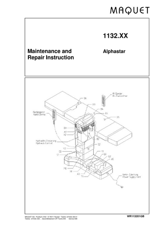
1. Design and function description
The essential components: -
transformer T1
-
battery charger A3, batteries G1/G2
-
DC-motor M1
-
hydraulic pump
-
valve control block 1 (Movements of table sections)
-
valve control block 2 ( Drive unit, Lock/Unlock)
-
drive unit incl. Motor M2 and controller board A5
-
pressure hoses, cylinders
-
Controller board A1, IR supplement A4
-
override functions A2 (handcontrol,Lock/Unlock)
-
override pump for manual unlocking of castors
-
hand control box / IR transmitter / foot switch
Please refer to the corresponding spare parts list for the variants used in the existing operating table.
WR1132.01GB
12.10.2000
Seite/Page: 1.02
Maintenance and Repair Instruction
ALPHASTAR 1132
Technical description
The 1132 model is an electro-hydraulic O.R. table using electrically controlled hydraulic valves. The oil flow is controlled by 5/3 directional solenoid valves (1) - (5 hydraulic connections, 3 positions of switched channels). Depending on the state of the control signal of the valve the piston rod (3) of the hydraulic cylinder is moved in our out, or it remains in its position.
The 5/3 directional solenoid valves operate along with double check valves (2) which are actuated by the oil flow coming from the solenoid valves. As long as the double check valve is in its rest position the hydraulic lines A and B remain closed to prevent the piston rod from being moved by any external mechanical load.
Power supply of the O.R. table – transformer and charging circuit
The mains voltage supply of the O.R. table is provided by means of a 2-line cable with a standard 3-pin connector. Supply cables are available with mains plugs either according to American or European standard. The transformer assembly T1 includes a voltage selector to enable adaptation to the present mains voltage (100...240V). The primary coil of the transformer consists of 4 separate windings, 2 of them for 104V each, 2 further for 12 V each. To connect the O.R. table to a mains voltage of e.g. 230V all the windings are switched in series via the voltage selector (232V). The lowest voltage setting available is achieved by switching the two 104V-windings in parallel circuit. A thermal protector fuse is integrated in the primary coil. If this fuse has blown the transformer must be replaced. The fuse can not be replaced.
WR1132.01GB
12.10.2000
Seite/Page: 1.04
Maintenance and Repair Instruction
ALPHASTAR 1132
The secondary windings of the transfomer provide 2x14V which are the supply voltages for the charger board A3. The following components are connected to the charger board A3: 2 batteries G1/G2, the 24V-DC motor, solenoid valves of valve block Y1, and the controller board A5 of the drive unit. All these components are located in the base of the O.R. table. On the charger board, the output voltages of the transformer (2x14V AC) are converted into separately regulated charging voltages of 13.75 DC for each battery.
Batteries G1/G2
The batteries of the O.R. table are maintenance-free lead-acid types. They supply the motors M1 and M2 (if installed) with 24 V DC. 2 batteries of 12 V each and a capcity of 16 Ah are sufficient for this purpose. The period of use until the batteries must be recharged depends on the current drawn by the motors and the actual running operation time of the motors M1/M2. The motor current is app. 7 A. The useful lifetime of the batteries is specified by the manufacturer as 5...6 years. Hence app. 300 cycles of charge/ discharge can be expected during the battery lifetime if they are charged once a week.
Controller of drive unit A5 and motor M2
The drive unit is offered as an option for the O.R. table 1132. It is actuated via the buttons „BACKWA.“ And „FORW.“ of the cable-connected hand control. The forward or backward movement of the table driven by motor M2 is controlled by the controller board A5.
WR1132.01GB
12.10.2000
Seite/Page: 1.06
Maintenance and Repair Instruction
ALPHASTAR 1132
Controller board A1 and Infrared receiver board A4
The controller board A1 is located under the black bellows. If IR remote control is installed an additional receiver board (A4) is plugged on. Both IR preamplifiers B1, B2 are connected to this board. The IR preamplifiers are located on the column one directed to the leg side the other to the head side. The receiver board A4 and the preamplifiers are continuously supplied by the permanent voltage 5Vp. The current consumption of these components is very low, hence there is only a very small loss of battery capacity. If there are more than one O.R. table with IR remote controls in the O.R. section (on the same floor) it is necessary to assign each table and the IR transmitter its own IR code (see technical description). 4 potentiometers B3/B4/B5/B6 for the „zero-positioning“ of the table top are connected to the controller board A1 which monitors and evaluates their position. The voltage at the output connector of the potentiometers must always be within a range of 0.16...4.84V.
Two micro switches, S1/S2, wired in series, provide a signal to the controller board A1 (X3.9 Slock) indicating that the O.R. table is locked on the floor. At the same time the 2 green LEDs of the cable connected hand control / override panel A2 are illuminated. To set the 4 twin swivel castors out to the floor the valve „UNLOCK“ is actuated until the pressure switch P on hydraulic block Y1 is activated at a pressure of 40 bar and the controller board receives the signal that the O.R. table is now ready to be moved. The 2 red LEDs are illuminated. If the LOCK/UNLOCK status of the O.R. table cannot be determined by the controller the red and green LEDs show intermittent flashing light.
WR1132.01GB
12.10.2000
Seite/Page: 1.08
Maintenance and Repair Instruction
ALPHASTAR 1132
Cable connected hand control
The hand control box consists of 2 housing parts, a PCB with pushbuttons for the individual functions, LEDs as indicators of the status, a foil keyboard, and a 4-line spiral cable (B5, 5V, 0V, DATA). Voltage supply of the hand control is provided by the lines 0V and 5V. The controller A4 is switched on/off via the line B5. The line DATA enables a bi-directional data transfer between the hand control and the controller board of the O.R. table. Serial data signals are sent by the hand control to actuate the desired function. The controller board sends signals to the hand control to control the status LEDs. To switch on the system the button „ON“ must be pressed. The status LEDs BATTERY, MAINS, ON, UNLOCK/LOCK, and NORMAL/REVERSE show a short flashing light. After this period only the LEDs indicating the current situation remain illuminated. The desired movement buttons can now be pressed. If no button is pressed within a period of 15 seconds the control unit is switched off automatically. The hand control can be switched off immediately by pressing the button „OFF“. For further information please refer to the brief operating instructions.
Override A2
The functions of the override panel are the same as of the hand control. The override panel enables an emergency operation if the hand control or the controller board A4 are defective. The difference to the hand control is that valves are actuated directly. The motor is actuated separately by the button „ON“ hence 2 buttons must always be pressed simultaneously („ON“ + movement button).
WR1132.01GB
12.10.2000
Seite/Page: 1.10
Maintenance and Repair Instruction
ALPHASTAR 1132
Infrared remote control
There is no bi-directional data transfer as with the cable connected hand control. The LED „Battery“ indicates the charge status of the accumulators of the hand control. The charge status of the batteries of the O.R. table is indicated by the LED on the OVERRIDE panel. The status LOCK/UNLOCK is indicated on the OVERRIDE panel as well. As a safety feature there is no possibility provided to actuate the drive unit via the infrared remote control.
Manual override pump
If a failure of the motor M1 or the hydraulic pump occurs this pump can be used to release the locking of the O.R. table from the floor. For detailed information please refer to the „Technical description“.
WR1132.01GB
12.10.2000
Seite/Page: 1.12
Maintenance and Repair Instruction
2.
ALPHASTAR 1132
Measurements (tests), electric and electronic system 2.1
Transformer primary connectors (1): The voltage corresponds to the setting at the voltage selector and to the local power supply
2.2
Transformer secondary connectors (2): 2 separate outputs of 14 Volt AC each at plug contacts
2.3
Battery charger (3):
Connect the O.R. table to the mains supply. Check the charging voltage at each battery.
Voltage
13.6 V
-
13.95 V DC
Charging current The charging current depends on the capacity of the batteries so that no information about the condition of the battery charger can be obtained.
2.4
Batteries (5):
Conduct the test (6) using an automotive light bulb (12 V, approx. 45 W) Good battery: Poor battery:
Bright light for 1 to 2 minutes (good charge) Light visibly darker after approx. 1 minute; voltage falls below 10V.
If a battery seems to be in poor condition, recharge and test it once again to verify the results. All two batteries should always be replaced at the same time.
WR1132.01GB
12.10.2000
Seite/Page: 2.02
Maintenance and Repair Instruction
2.5
ALPHASTAR 1132
Motor test (M1)
Detach the plugs X3.1 at the charging unit (3); insert the amperemeter in one of the cables, press any function button and move the function until its final position (and the max. pressure of 100bar) is reached.
The unit must draw between 6.5 and 7,5 Ampere.
If more than 9 A is drawn, then either the motor (7) or the pump (8) is defective. Remove the motor and measure the power drawn by the separated motor.
When operating with no load,
the max. admissible value is 0.6 A.
Replace the motor if the current is higher. If the motor proves to be OK, then replace the pump. Check the power value again (< 8A) after having installed the new pump.
Note: Using the operating table over an extended period of time with the motor drawing an excessive current (> 8A) can damage the battery charger (3) and, in rare cases, even the hand control unit.
2.6
Motortest (M2 - drive unit)
Adjustment of the limit switch S3 = Switching threshold app. 1mm before the lower end position is reached.
Note: If the limit switch S3 is shorted (contact closed) during troubleshooting and the button „Drive“ is not pressed within a period of 3 sec. the controller unit will detect this condition as a fault. The O.R. table must be switched off the short must be removed and testing can be resumed.
Current consumption of the drive unit motor (overload protection at 13Amp.) With no mechanical load: 0.4 A Nominal current:
WR1132.01GB
4.9 A, app. <4A under normal drive condition
12.10.2000
Seite/Page: 2.04
Maintenance and Repair Instruction
2.7
ALPHASTAR 1132
0”-position potentiometers
B3=Tilting, B4=Trendelenburg, B5=Back section, B6= Leg plate
Voltage supply 5 V, measured when connected between the red and black wires.
The 0-position corresponds to approx. 2.5 V measured between the red and green or the black and green wires (voltage divider), i.e. half of the setting range of the potentiometer corresponds to 2.5V.
Troubleshooting: When pressing the "0" buttons, the function moves into the opposite direction -> exchange the black and red wires. A continuous acoustic signal is generated when pressing the "0" buttons -> a potentiometer is defective or outside its limit range (0.5 ...4V).
-> Replacement or adjustment of the
potentiometer.
Note: An adjustment can be carried out manually by means of a screwdriver or alternatively with the IR-Tester (see „1132“-mode). The standard adjustments of of FLEX- /REFLEX angle positions can be programmed by means of the tester as well.
WR1132.01GB
12.10.2000
Seite/Page: 2.06
Maintenance and Repair Instruction
2.8
ALPHASTAR 1132
Control unit and receiver board
The functions of the control unit can be simulated by pressing the override buttons A2. If the operating table function is actuated, either the controller board A1 or the hand control is defective. Try another hand control/IR-transmitter. If the O.R. table does still not respond the controller board is defective.
Functions of the hand control box or of the foot switch can be tested by means of the IR-Tester within the mode „READ DATA BUS 1132“.
Test the 5V-supply of the hand control box.
2.9
IR remote control
Test the IR transmitter and charging station using the IR tester – mode „1132“ Check equal settings of the selector switches (5/7) of boards (2/8). Test the IR receiver/preamp. B1/B2 by means of the IR tester. Test the range of transmission of the IR transmitter by means of the IR tester modus „IR detect VV“ or „IR detect ASIC.
If the IR transmitter emits a continuous tone when a function is actuated, the IR code has been set but not acknowledged – see technical description.
WR1132.01GB
12.10.2000
Seite/Page: 2.08
Maintenance and Repair Instruction
ALPHASTAR 1132
2.10 Function LOCK/UNLOCK
The LEDs of the pushbuttons LOCK/UNLOCK indicate the current status of the O.R. table.
The illuminated LED „UNLOCK“ indicates that the castors are positioned towards the floor, microswitches S1 and S2 are not activated (open) and the contact of the pressure switch „UNLOCK“ is closed. Switching threshold of the pressure switch: app. 40 bar.
Flashing light of both LEDs LOCK/UNLOCK indicates that the status is pending, i.e. the O.R. table is being switched from LOCK to UNLOCK or in reverse order. Flashing light of both LEDs can also indicate that one of the microswitches has not opened though the castors are fully set out onto the floor.
WR1132.01GB
12.10.2000
Seite/Page: 2.10
Maintenance and Repair Instruction
ALPHASTAR 1132
3. Measurements and tests, hydraulic system Note: Always remove all load from the cylinder affected before opening any hydraulic connection! Move the piston rod of the cylinder to the position in which it is relieved of load. Normally this condition is achieved in the lowermost position. The cylinders of the castors are relieved of load in the „LOCK“-position
Use the spacer plate from the tool kit when working on the elevation function. This measure will prevent the operating table from excessive oil loss.
3.1
System pressure
The system operating pressure is 100 bar (for older models 120 or 130 bar). This pressure can be measured at any cylinder. To do so, connect the pressure gauge to the “A” end and actuate the appropriate function; keep the function actuated until the uppermost position is reached. It is also possible to check the pressure at the outlet P of the hydraulic unit.
If the working pressure is too low, an adjustment can be made at the “DB 100” (1) pressure limiter valve. The nominal pressure is 100 +5 bar.
If this does not rectify the problem, then the DB 100, the pump, or the motor is defective.
WR1132.01GB
12.10.2000
Seite/Page: 3.02
Maintenance and Repair Instruction
3.2
ALPHASTAR 1132
Checking the oil level
Raise the operating table to its uppermost position and align the table top horizontally („0“ button). Remove the 2 screws (1) of the base casing (3), pull the base casing off the base and fix it.
The oil level must be above the minimum but below the maximum mark on the tank (4).
3.3
Hydraulic cylinders
Before checking any particular hydraulic cylinder, it is necessary to test the corresponding check valve for its correct function (measure with no cylinder connected).
Note: The pressure (100 bar) must not drop below 70 bar within a period of 30 minutes.
If this proves to be in satisfactory condition, then carry out the cylinder pressure measurements. Use the measuring adapters (5) to connect the pressure gauges (150 bar) to the “A” and “B” lines. Press and hold the appropriate button on the control until the mechanical stop is reached and the pressure rises to the maximum value.
WR1132.01GB
12.10.2000
Seite/Page: 3.04
Maintenance and Repair Instruction
3.4
ALPHASTAR 1132
Leaks at the check valve (3)
It will be necessary to detach the “A” and “B” lines at the particular actuator cylinder to test for internal leakage in the check valve (3). Then connect the test adapter (4) from the tool kit (3111.4913) together with the pressure gauge. Press the “up” button.
1st step (I)
The pressure of 100 bar must not fall below 70 bar within a period of 30 min. The presure will rise to the maximum (100 bar). Release the function control button; the check valve closes.
Observe pressure characteristic "Y" (see diagram).
If the pressure falls abruptly by 10 - 30 bar (approx.) and then remains at a constant level, the test lead must be bled and the test repeated.
2nd step (II) Set pressure limiter valve DB 100 to 50 bar. Press the "up" button, the pressure rises to a maximum value of 50 bar. Release the button, the check valve closes.
The pressure of 50 bar must not fall below 35 bar within a period of 15 min.
Observe pressure characteristic "Z" (see diagram).
WR1132.01GB
12.10.2000
Seite/Page: 3.06
Maintenance and Repair Instruction
4.
ALPHASTAR 1132
Troubleshooting - what to do, if .. For troubleshooting, the sequence of parts to be checked must always be observed to allow safe and well-aimed detection of the fault.
Arbitrary checking or replacement of components will certainly not be helpful. Also, the most "popular" replacement of microchips on the boards is not a very professional way to resolve the problem!
How to proceed:
check e.g. transformer; battery charger - charging voltage; battery capacity; motor current consumption; voltage, pump output pressure, - and: override functions, test functions with hand control and IR-tester, receiver board, preamplifiers
4.1
Motor running without any of the control buttons being pressed
Detach the control unit. If the motor stops try another hand control. If the motor still continues running, check the battery charger. If the problem persists, check the connecting cable from the battery charger to the hand control unit.
4.2
Motor running but no function is executed when hand control button is pressed
Test the function button on the control unit -> switching stroke of the button is too long. Check the function by pressing buttons on the override panel. If there is still no movement check the valve in question and its wiring. To determine whether the fault is to be found in the electrical or hydraulic system exchange the valve supply cables with the cables of another function that is still working. Check whether the same movement continues to be not working.
If the faulty movement can still be actuated by pressing the button on the override panel the valve wiring and the valve itself is not defective. Continue testing electrical components such as the hand control. Use the „hand control“ and IR- functions of the IR tester. (see also „testing of the hand control“)
WR1132.01GB
12.10.2000
Seite/Page: 4.02
Maintenance and Repair Instruction
4.3
ALPHASTAR 1132
Red light on the battery indicator of the cable connected hand control or the override panel - although the batteries have been charged for an extended period of time (8 to 15 hours)
Test the batteries, the battery charger as well as the motor. Test the transformer: If the battery charger stops charging the batteries before they are completely charged, the transformer gets too warm and the charger is switched off by its monitoring function via the NTC (connection X1.5, X1.6). For testing, detach the NTC connections. If the battery charging has now improved, exchange the transformer -> too fast overheating.
4.4
Operating table cannot be operated using the IR remote control
Check the system code setting of the IR transmitter and IR decoder. See techn. description.
Test with cable control unit.
If there is still no reaction, check the transmission power of the IR remote control using the IR tester.
Test the charging station of the IR transmitter using the IR tester.
Test the operating table function with another IR transmitter.
Test the function of the IR transmitter previously used with another operating table.
Test the operating table function by means of the IR tester.
WR1132.01GB
12.10.2000
Seite/Page: 4.04
Maintenance and Repair Instruction
4.5
ALPHASTAR 1132
The elevation function effects no rise and moves downwards either very slowly or not at all, other functions work properly.
Test the cylinders, measure the pressure, too high flow resistance, system pressure too low.
The guides may be set too tight, table with no additional load: 40...50bar while moving upward (2)
Test the check valves, measure the pressure. (I,II)
4.6
Trendelenburg or tilt functions exhibit play after a short period of time (app. 1...2 days after adjustment)
Test the check valves.(I,II,)
Measure the pressure at the A and B lines.
Test the cylinders. (1)
4.7
The operating table does not function at all
Connect the table to the mains socket. If the table then functions properly, charge the batteries for about ½ hour, and then check the functions again with the table disconnected from mains supply.
Check the setting of the code switches of the IR decoder board and the transmitter.
Measure the current of the motor.
If the table still does not function, test the transformer, the batteries and the motor.
WR1132.01GB
12.10.2000
Seite/Page: 4.06
Maintenance and Repair Instruction
ALPHASTAR 1132
5. Repairwork, replacement of hydraulic and mechanical components
5.1
Replacement of twin swivel castors (1)
O.R. table must be in „LOCK“ position. (swivel castors must be released off the floor). Adjust the table top into its level position. Elevate the column to app. half way of height. Remove the 2 screws (2) from each end of the base cover (3). Pull the base cover off in an upward direction and secure it on the table top with straps.
Warning: Be aware of the heavy weight of the O.R. table!
Tilt the whole O.R. table and lay it down on the floor (this work requires 2 persons) see picture. Remove the fixing screws (4) of the 3 spring bolts (5).
Extend the spring (8) by means of appropriate tools (plier, wire etc.) so that the spring bolt (5) can be removed. Remove the screws (6) of the guide bolts (7). Replace the swivel castor.
Do not stretch the springs (8) more than necessary! (max. 67 mm)
WR1132.01GB
12.10.2000
Seite/Page: 5.02