HANS RUDOLPH
PNT Instruction for Use Rev D Oct 2017
Instruction for Use
4 Pages
Preview
Page 1
HANS RUDOLPH, inc. ®
MAKERS OF RESPIRATORY VALVES SINCE 1938
M Devices Group / EC Rep Ltd
TEL: (913) 422-7788 U.S.A. & CANADA (800) 456-6695 FAX: (913) 422-3337 E-Mail: [email protected] 8325 COLE PARKWAY, SHAWNEE, KANSAS 66227 U.S.A. EN
HANS RUDOLPH, INC. PNEUMOTACHOMETER (PNT) INSTRUCTIONS FOR USE
PNEUMOTACHOMETER (PNT) VON HANS RUDOLPH, INC. GEBRAUCHSANWEISUNG
DE
FR
PNEUMOTACHOMETRES (PNT), HANS RUDOLPH, INC INSTRUCTIONS D'UTILISATION PNEUMOTACHIMETRO, HANS RUDOLPH, INC ISTRUZIONI PER L'USO
IT
NEUMOTACÓMETRO (PNT), HANS RUDOLPH, INC. INSTRUCCIONES DE USO
ES
NL
PNEUMATISCHE TACHOMETER (PNT), HANS RUDOLPH, INC INSTRUCTIES VOOR HET GEBRUIK SV
PNEUMOTACHOMETER (PNT), HANS RUDOLPH, INC BRUKSANVISNING 14 13
15
1
4
5
7
6
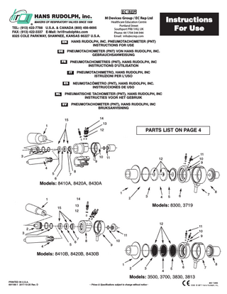
PARTS LIST ON PAGE 4
12
2
3
9
8
10
11
3
1
14
2
13
15
11 10 9
12
Models: 8410A, 8420A, 8430A 1
Instructions For Use
Healthcare Education Centre Portland Street Southport PR8 1HU, UK Phone: 44 1704 544 944 Email: [email protected]
3
12
4
Models: 8300, 3719 12
2 4
5
6
7
8
Models: 8410B, 8420B, 8430B
PRINTED IN U.S.A. 691199-1 2017-10-25 Rev. D
9
10
2
3
4
5
6
Models: 3500, 3700, 3830, 3813
• Prices & Specifications subject to change without notice •
8
11 10 9
11
1
7
6
5
7
8
HANS RUDOLPH, INC. PNEUMOTACHOMETER (PNT) INSTRUCTIONS FOR USE
A. Intended Use Pneumotachometers (PNT) are designed for use as a component of a respiratory flow measurement system. The pneumotach converts the flow of gas into a proportional linear signal of differential gas pressure for input into a differential gas pressure transducer. The output from the differential pressure transducer is used for flow and volume measurements. The end user is required to design and assemble the additional instrumentation required to integrate the PNT into the flow system. PNT's are available in a wide range of sizes as specified by the flow range and volume dead space. Applications range from pulmonary function testing, exercise testing and respiratory research. Heater controllers are available for these PNT's. WARNING: This pneumotach is not intended for long term continuous flow monitoring in a humidified ventilator circuit. Moisture can occlude the screen. Never leave PNT in the ventilator circuit unattended by qualified personnel. B. Directions for Use For detail information contact Hans Rudolph for the PNT Service and Instruction Manual 691038 and Data sheet 691037. Connect the port tubes (inlet, outlet) to the gas flow circuitry. Complete the pressure connection between the differential pressure taps on the PNT and the appropriate ports of the differential pressure transducer. The flow will then be detected by pressure changes recorded in the transducer amplifier recording system. A heater control is recommended for the PNT's that are used in a humid respiratory circuit. The heater control reduces condensation on the screens (resistive element) of the PNT which would affect the differential pressure output to the transducer. Heated PNT's should be evaluated first in humidified circuits prior to use by visual inspection of the screens. WARNING: If humidity collects on the screens do not use the PNT in this flow circuit. C. Reprocessing Instructions Scope This guidance is directed to personnel responsible for decontamination of Hans Rudolph pneumotachs. Product Classification These PNT's are classified as reusable devices. These PNT's are supplied clean, non sterile. These PNT's fall into the semi-critical device category based on potential risk of infection. This device will come into contact with intact mucous membranes but will not penetrate body surface. Although sterilization is recommended whenever practical, high level disinfection is acceptable. High level disinfection and sterilization is recommended by using liquid glutaraldehyde disinfectants approved as sterilant/disinfectants by the Environmental Protection Agency and cleared for marketing for use on medical instruments by the Office of Device Evaluation, Center for Devices and Radiologic Health, Food and Drug Administration. High level disinfectants are simply sterilants used at a shorter exposure time. Precautions 1. Pneumotachs may become contaminated with patient secretions during use thus, they are cleaned and subjected to high level disinfection or sterilization between uses on different patients. 2. Thorough cleaning of these PNT's is required prior to the sterilization or disinfection process. 3. Follow disinfection with appropriate rinsing, drying and packaging, taking care not to contaminate the PNT's in the process. 4. Use sterile water for rinsing reusable semi-critical devices used on the respiratory tract after they have been chemically disinfected. The introduction of detergents to the disinfectant solution, which can occur if the device is inadequately rinsed after cleaning, can alter the pH of the solution and reduce it's effectiveness. Inadvertent dilution of the disinfectant solution by wash or rinse water on wet devices also will lower the disinfectant concentration. Organic matter left on the device can protect microorganisms or inactivate the active chemical agent in the disinfectant. 5. Wash hands before and after contact with mucous membranes, respiratory secretions, or objects contaminated with respiratory secretions, whether or not gloves are worn. 6. The responsibility for handling, cleaning and decontaminating reusable medical devices should be assigned to trained, qualified individuals. 7. Appropriate protective clothing (gloves, masks, eye protection, gowns) will minimize the potential for personal exposure to blood borne and other disease-producing organisms. 8. Immediately separate and contain soiled reusable devices at the point of use and transport to the decontamination area so as to minimize risk of personal contact with contaminants. 9. Liquid chemical disinfectants product label must include information on use-pattern, use-life and storage life of the product. Be sure you understand these terms and follow the manufacturerʼs instructions. These factors apply to the effectiveness of the disinfectant solution. 10. A disinfectant solution is only effective if it can contact all surfaces of the items to be disinfected or sterilized. 11. Adequate ventilation is required in the disinfection area to evacuate the chemical vapors from glutaraldehyde. Use lidded containers for the disinfectant solution when appropriate. The inhalation of fumes from disinfectant solutions or skin contact with liquid disinfectants can be hazardous to personnel. D. Decontamination Introduction These recommended practices provide guidelines to assist the health care personnel in the decontamination, cleaning, maintenance, handling, storage and/or sterilization of Hans Rudolph Pneumotach components. Decontamination is a multi-step process that includes preparation at point of use, thorough cleaning and rinsing and a microbicidal process. Thorough cleaning and rinsing are the first and most important steps in the reprocessing of any reusable medical device. Without thorough cleaning and rinsing it might not be possible to achieve high level disinfection or sterilization of the device. The purpose of cleaning and rinsing is to remove all adherent visible soil, to reduce the number of particulates and microorganisms, and to reduce the amount of pyrogenic and antigenic material. Any organic material, lubricants, or residual cleaning agents remaining on a device can inactivate liquid chemical disinfectants/sterilants as well as protect microorganisms from destruction. The second step in decontamination is the microbicidal process which is defined as a process to provide a particular level of microbial lethality (kill). Hans Rudolph Pneumotachs are classified as "semi-critical" items which are devices that come into contact with intact mucous membranes. Semi-critical devices at a minimum require a high-level disinfection procedure. Sterilization is not absolutely essential. All Hans Rudolph Pneumotachs require complete or partial disassembly for cleaning and disinfection. It is the responsibility of the user (health care personnel) for ensuring that the cleaning methods recommended by Hans Rudolph can be duplicated in their environment, that appropriate tools, and replacement parts are available and that Hans Rudolph instructions are followed correctly. E. Cleaning Agents/Supplies for Hans Rudolph Components Mild detergents with a neutral pH(7) are recommended for cleaning Hans Rudolph Pneumotachs. Grease cutting dishwashing detergent is helpful in removing the silicone lubricant found on many components. Use warm water (22°-43°C) with the mild detergent. To be effective, cleaning agents must assist in the removal of residual organic soil without damaging the device. Cleaning agents should be used in the correct dilution/concentration and at the correct temperature in accordance with the cleaning agents manufacturer's directions. It is ultimately the user's responsibility to choose the correct cleaning agent, based on the instructions of the device manufacturer and any recommendations of the cleaning manufacturer. Certain cleaning agents may damage metal or other device materials. Do not use cleaning agents containing bleach or alcohol. Cleaning supplies are very basic, usually consisting of a surgical scrub brush, chenille pipe cleaners, cotton or foam tipped applicators, soft brushes, and soft cloths. Cleaning supplies should be cleaned and disinfected or sterilized daily. Water Quality: Tap water is acceptable for use in cleaning Hans Rudolph reusable Pneumotachs. Hans Rudolph PNT's should be soaked, cleaned and rinsed in tap water at 22°-43°C to prevent the coagulation of solid substances onto the device and thus facilitate the removal of debris. Enzymatic detergents with a neutral pH(7) are recommended when processing difficult-to-clean devices with dried-on matter. Soaking valve components in an enzymatic detergent solution can effectively remove visible debris except for lubricants thus providing an acceptable alternative to manual cleaning. Rinsing is necessary to remove all traces of detergent and extraneous debris. F. Cleaning Methods Step 1 Preparation at Point of Use The cleaning of reusable devices usually begins soon after use. At the point of use, personnel wearing gloves and other protective attire separate disposable items or components from reusable devices and discard them in appropriate receptacles. Soil is wiped from device surfaces with a moist sponge or towel. The soiled/contaminated items are then contained in a manner that will reduce the risk of personal exposure to pathogens. Breathing valve devices are usually placed in a basket, tray or rigid container for transportation to the processing area, usually transported in or on a cart, as hand carrying of soiled items is discouraged. Step 2 Inspection Inspect the PNT components for damage at all stages of handling. If damage is detected on any of the components it should be identified and documented. Complete the disinfection/sterilization process and contact Hans Rudolph for guidance on replacement components. Step 3 Presoak Protective attire is required of personnel handling contaminated devices. At the processing area soak or rinse the device in tap water 22°-43°C. If an enzyme product is required, soak for one to two minutes. Remove and examine, extend the soak time for components with dried-on matter. Prolonged soaking of components may be detrimental, causing damage to the component surfaces. Step 4 Disassembly (Pneumotachs) Refer to the PNT diagram. Protective attire is required of personnel handling contaminated devices. The person(s) to whom the job of reprocessing Pneumotachs is given should have the opportunity to become completely familiar with the mechanical aspects of these PNT's. The Pneumotachs must be completely disassembled to expose all surfaces to the cleaning process. Tools/Supplies 1. Some Pneumotachs require special wrenches for disassembly. These are provided with the pneumotach. 2. Silicone lubricant (P/N 660170) may be required on assemblies where orings are used. Instructions 1. If the PNT is heated, turn off power to the heater control and unplug heater shell and cable assembly from the rear panel of the control. 2. Unscrew the two pressure taps counterclockwise from the PNT body. 3. Unscrew the small flange port counterclockwise from the PNT body. 4. Pull the heater shell or non heated shell completely from the PNT body. Remove by hand, do not use a tool that could damage the heater element. 5. Unscrew the large flange port counterclockwise from the PNT body. Some models are provided with a special wrench for port removal. 6. Carefully remove the oring directly inside the PNT body where the large flange port was threaded. A tool such as HRI 905000 dental pick may be helpful for this operation. 7. Remove the screen and/or spacer assemblies (3pc.) from the PNT body by gently tapping the open body end on a flat clean surface (table top). NOTE: Each screen or spacer assembly is marked by dots (1, 2, or 3) designating the order in location of the assembly in the body. Number 3 screen is installed last. Each screen/spacer assembly is engraved with the PNT serial number to assure keeping the calibrated PNT components together. 8. Remove orings and seals from mating components where applicable. 9. Installed hose barbs should not be disassembled. 10. Care should be taken to ensure that all small parts (orings, pressure tap seals, pressure taps, screens) are contained to prevent loss. Pneumotach assemblies are calibrated devices and their components are noninterchangeable with other PNT's. Keep the components of each assembly together to ensure correct assembly. 11. Always replace damaged components. Step 5 Manual Cleaning Protective attire is required for personnel handling contaminated devices. Manual cleaning must be done in a manner that protects personnel handling the devices from aerosolization and splashing of infectious material. 1. Manual cleaning of the PNT components should be done under water in cool to luke warm water (43°C maximum). Use a neutral pH(7) mild detergent. Typical concentration of detergent is one ounce to 3.8 liters of water. Water hardness, temperature and the type of soil affect the effectiveness of the detergents; the detergent manufacturer's instructions should be consulted. Use a small soft brush to scrub all detachable parts. Visually inspect the screen assemblies for debris build up. If this is the case soak the screen assembly in a mild detergent followed by a gentle brush cleaning (toothbrush). Use an enzymatic detergent (neutral ph) soak if the mild detergent does not break down the debris buildup. Abrasive cleaning compounds and implements can damage these PNT components and should not be used. Additional cleaning supplies may be required to clean stubborn stains or hard-to-reach areas. PRINTED IN U.S.A. 691199-2 2017-10-25 Rev. D
• Prices & Specifications subject to change without notice •
2. PNT components must be thoroughly rinsed with clean water to remove the detergent residuals and debris from the components. Use a flowing triple rinse cycle at a minimum with tap water. 3. Dry all components thoroughly using soft clean cloths or disposable paper towels. Components should be dry to prevent dilution of the disinfectant used in subsequent steps. 4. The heater shell and cable assembly are not in communication with the patient and therefore do not require high level disinfection. To clean this assembly spray and wipe dry with a mild detergent or disinfectant solution. Step 6 Manual Disinfection High level disinfection of all pneumotach components must be performed after each use. The disinfectant/sterilizing agent must contact all surfaces to ensure disinfection or sterilization. High level disinfection of Pneumotach components ensures patient safety and minimizes the risk of infection. Use only liquid glutaraldehyde disinfectant solutions approved as sterilants/disinfectants by the Environmental Protection Agency and cleared for marketing use on medical devices by the Office Device Evaluation, Center for Devices and Radiologic Health, Food and Drug Administration. For a list of approved products contact Hans Rudolph, inc. When used according to the manufacturerʼs instructions a high level disinfectant destroys all microorganisms, but not necessarily all bacterial spores. The chemical agent should be sporicidal when used in recommended concentrations, temperatures and contact time. Manufacturerʼs instructions will include information on monitoring chemical concentration of the disinfection solution for use-life effectiveness. Disinfectants can become diluted with water that is retained in the valve components or accessories. The fumes of glutaraldehyde can irritate the mucous membranes of eyes, nose and throat. Some people develop allergic reactions to glutaraldehyde that can cause skin rashes, headaches and breathing difficulties. Containers of glutaraldehyde should be kept closed and in a well ventilated area. Gloves should be worn made of butyl or nitile rubber. Do not use latex rubber gloves. The concentration of glutaraldehyde in the air should not exceed .2 ppm. 1. Determine the required soak temperature and time of the sterilant/disinfectant and assure that these requirements are met. 2. Activate the glutaraldehyde solution by mixing the components per the manufacturerʼs instructions. Use the concentration testing devices sold by the manufacture to determine that the solution is above the minimum effective concentration. 3. Pour the activated glutaraldehyde solution into an appropriate sized basin. 4. Completely immerse the Pneumotach components in the basin. Assure that all channels and cavities are filled with disinfectant and that no air pockets remain within the components. 5. Cover the disinfectant soaking basin with a tight fitting lid to minimize chemical vapor exposure. 6. Soak the PNT components for the time specified by the disinfectant solution manufacturer to achieve high level disinfection. Use a timer to ensure adequate soaking time. Step 7 Rinse After Manual Disinfection Adequate rinsing must follow disinfection to remove all traces of the toxic residues of the disinfectant left on the PNT components. Sterile water rinse is preferred over tap water. Tap water may contain a variety of microorganisms which could recontaminate the valve components. 1. Rinse 1: Fill a basin with 7-8 liters of water (preferably sterile water). Place the PNT components into the basin and thoroughly rinse all the components for a minimum of one minute. Empty basin. 2. Rinse 2: Fill a basin with 7-8 liters of water (preferably sterile water). Place the PNT components into the basin and thoroughly rinse all the components for a minimum of one minute. Empty basin. Step 8 Drying To prevent the growth of waterborne organisms, the PNT components should be thoroughly dried prior to reassembly and storage. 1. Dry thoroughly using a soft cloth (preferably sterile) or disposable paper towels. Step 9 Inspection All components should be visually inspected for cleanliness, proper function and freedom of defects. Visual inspection provides evidence of thorough cleaning and proper functioning of all PNT components. PNT's in poor working condition are hazardous to personnel and patients. 1. Visually inspect all components for cleanliness. If there are signs of residue from the detergent or disinfectant repeat the previous steps. If there are any signs of remaining stains or organic debris repeat the previous steps. If the cleaning and disinfection steps have been repeated with no improvement eliminating residual or stains etc. then dispose of the components and replace. 2. Visually inspect all components for defects. Check the screen assemblies for damage to the screen material such as holes or tears. Check the rubber parts for tears, nicks, hardening or stiffening, deformation or distortion. Check the plastic parts for crazing, cracking or stripped threads. Any defective parts should be discarded and replaced. 3. Visually inspect all metal components for corrosion. Replace any metal components showing rust or chipped plated surfaces. Step 10 Reassembly Refer to the previous PNT diagrams. Use appropriate personal protective clothing to assure that you do not recontaminate the components. 1. All orings should be lubricated with an approved silicone lubricant (HRI P/N 660170). Apply a light film of lubricant with your fingers to all surfaces of the oring. 2. Install orings and tube seals on the pressure taps. 3. Install orings on the flange ports where applicable. 4. Place the body on table with large hole opening upward. Note the location of the slot in this opening which mates with pin on side of the screen assemblies. 5. Select screen (or spacer) assembly with one dot facing up. Place into the body with alignment pin on side of screen assembly mating with slot in body. 6. Repeat the same process with the two dot screen assembly. 7. Repeat the same process with the three dot screen assembly. Note: the screen assembly must be placed in flat to avoid binding. If the screen assembly binds, tap lightly on the body assembly until the screen lays flat. Do NOT PUSH ON THE SCREEN MESH. 8. Insert oring in the groove above the stacked screen assemblies within the body. 9. Screw the large flange port tightly (hand tighten only) to the body. 10. Place the heater or non heated shell assembly onto the body. 11. Screw the small flange port onto the body (hand tighten only). 12. Screw the pressure taps into the body until the tap oring is compressed 1/2 turn. Step 11 Functional test The PNT should be inserted into the flow measurement system and a recalibration procedure should be performed. If the PNT calibrates accurately and meets the system specification then it is functioning acceptably. Step 12 Storage Confirm that the PNT is completely dry prior to storage. Pneumotachs should be stored in a way that prevents recontamination or damage between uses. 1. Place PNT assembly in a clean plastic bag and heat seal the end. 2. Label the bag documenting that it has been disinfected, date, initials, PNT part number and description. G. Reuse Life Hans Rudolph Pneumotachs when maintained properly and reprocessed per these instructions should function within specifications for 100 reuses. Visual inspection of all the components during each reprocessing cycle will identify any defects. The functional test as described in Section F, Step 11 will determine if the valve is functioning properly. H. Ambient Conditions 1. Temperature: 5ºC to 40ºC 2. Relative Humidity: 0% to 95% (non--condensing) I. Warnings 1. This pneumotach is not intended for long term continuous flow monitoring in a humidified ventilator circuit. Moisture can occlude the screen, never leave PNT in the ventilator circuit unattended by qualified personnel. 2. Do not ethylene oxide, steam sterilize or pasteurize these valves. 3. Use only approved liquid glutaraldehydes (see Section F, Step 6). Do not use alcohol or bleach solutions. 4. Glutaraldehyde solutions are hazardous to humans. 1. Do not get into eyes, on skin or on clothing. 2. Use in well ventilated area in closed containers. 3. For emergency, safety or technical information about the glutaraldehyde solution contact the manufacturer. 5. Appropriate personal protective clothing should be worn when cleaning and sterilizing/disinfecting soiled devices. 6. Contaminated, reusable devices must be thoroughly cleaned prior to disinfection or sterilization, since residual contamination will decrease effectiveness of the glutaraldehyde solution. 7. It is the user's responsibility to validate any deviations from this recommended method of processing. 8. Federal (USA) law restricts this device to sale by or on the order of a physician. J. Risks The Risk of any harm to patients and clinicians caused by using these PNTs is remote. Steps have been taken to greatly reduce the probability of occurrence of potential hazards: 1. Flow measurements or calibration errors 2. Inhaled or contacted contaminants (particulates, microbes, fluids, chemicals) 3. Biosensitivity to PNT materials 4. Excessive rebreathed dead space or breathing resistance 5. Skin exposure to excessive PNT shell temperature 6. Excessive electrical leakage current (Controller) 7. Electrical fire (Controller) 8. Flammable anesthetic/oxygen fire (Controller) K. Safety Information Safety or technical information regarding Hans Rudolph Pneumotachs can be obtained from Hans Rudolph, inc., Phone 913-422-7788, USA & Canada 800-456-6695, Fax 913-422-3337, or by contacting your Hans Rudolph representative. L. References 1. "Labeling Reusable Medical Devices for Reprocessing in Health Care Facilities: FDA Reviewer Guidance", Rockville, MD, FDA Center for Devices and Radiological Health, Office of Device Evaluation, April 1996 2. Association for the Advancement of Medical Instrumentation. "Designing, Testing, and Labeling Reusable Medical Devices for Reprocessing in Health Care Facilities: A Guide for Device Manufacturers". AAMI TIR No. 12-1994. Arlington (Vir.): AAMI, 1194c. AAMI Technical Information Report 3. Association for the Advancement of Medical Instrumentation. "Safe Handling and Biological Decontamination of Medical Devices in Health Care Facilities and in Nonclinical Settings", ANSI/AAMI ST351196, Arlington (Vir.) AAMI, 1996 American National Standard. 4. Centers for Disease Control. "Guidelines for Handwashing and Hospital Environmental Control". Section 2: "Cleaning, Disinfecting, and Sterilizing Patient Care Equipment." Atlanta: CDC, 1985 5. Centers for Disease Control. "Guideline for Prevention of Nosocomial Pneumonia." Infection Control and Hospital Epidemiology 1194; 15:587-627 6. Rutala, WA. APIC "Guideline for Selection and Use of Disinfectants." American J. INFEC. Control, 1190, Vol. 18 No. 2, pp 99-117.
PRINTED IN U.S.A. 691199-3 2017-10-25 Rev. D
• Prices & Specifications subject to change without notice •
EN
Models 8410-A, 8420-A, 8430-A 1. Large Flange Wrench 2. Large Flange 3. O-ring 4. Screen Insert Tool 5. No. 3 spacer 6. No. 2 spacer 7. No. 1 spacer 8. Body 9. Heater Shell Assy. 10. O-ring 11. Small Flange 12. Tube Seal 13. O-ring 14. Pressure Tap 15. Screen Set Models 8410-B, 8420-B, 8430-B 1. Large Flange Wrench 2. Large Flange 3. O-ring 4. Screen Insert Tool 5. No. 3 Spacer 6. No. 2 Spacer 7. No. 1 Spacer 8. Body 9. Heater Shell Assy. 10. O-ring 11. Small Flange 12. Tube Seal 13. O-ring 14. Pressure Tap 15. Screen Set Models 8300, 3719 1. Large Flange Wrench 2. O-ring 3. No. 3 Spacer 4. No. 2 Spacer 5. No. 1 Spacer 6. Body 7. Heater Shell Assy. 8. Small Flange 9. Tube Seal 10. O-ring 11. Pressure Top 12. Screen Set Models 3500, 3700, 3830, 3813 1. Large Flange 2. O-ring 3. No. 3 Screen 4. No. 2 Screen 5. No. 1 Screen 6. Body 7. Heater Shell Assy. 8. Small Flange 9. Tube Seal 10. O-ring 11. Pressure Tap ES 12. Screen Set
DE
Modelos 8410-a, 8420-a, 8430-a 1. Llave para brida grande 2. Brida grande 3. Junta tórica 4. Herramienta para insertar pantallas 5. Separador no. 3 6. Separador no. 2 7. Separador no. 1 8. Cuerpo 9. Conj. Armazón térmico 10. Junta tórica 11. Brida pequeña 12. Sello del tubo 13. Junta tórica 14. Toma de presión 15. Juego de pantallas Modelos 8410-b, 8420-b, 8430-b 1. Llave para brida grande 2. Brida grande 3. Junta tórica 4. Herramienta para insertar pantallas 5. Separador no. 3 6. Separador no. 2 7. Separador no. 1 8. Cuerpo 9. Conj. Armazón térmico 10. Junta tórica 11. Brida pequeña 12. Sello del tubo 13. Junta tórica 14. Toma de presión 15. Juego de pantallas Modelos 8300, 3719 1. Brida grande 2. Junta tórica 3. Separador no. 3 4. Separador no. 2 5. Separador no. 1 6. Cuerpo 7. Conj. Armazón térmico 8. Brida pequeña 9. Sello del tubo 10. Junta tórica 11. Toma de presión 12. Juego de pantallas Modelos 3500, 3700, 3830, 3813 1. Brida grande 2. Junta tórica 3. Separador no. 3 4. Separador no. 2 5. Separador no. 1 6. Cuerpo 7. Conj. Armazón térmico 8. Brida pequeña 9. Sello del tubo 10. Junta tórica 11. Toma de presión 12. Juego de pantallas
PRINTED IN U.S.A. 691199-4 2017-10-25 Rev. D
FR
Modelle: 8410-A, 8420-A, 8430-A 1.Großer Flanschschlüssel 2. Großer Flansch 3. O-Dichtring 4. Siebeinsatz-Vorrichtung 5. Siebeinsatz 1 6. Siebeinsatz 2 7. Siebeinsatz 3 8. Mittelstück 9. Heizkörper 10. O-Dichtring 11. Kleiner Flansch 12. Dichtungsrohr 13. O-Dichtring 14. Druckanschluß 15. Siebeinbausatz Modelle: 8410-B, 8420-B, 8430-B 1. Großer Flanschschlüssel 2. Großer Flansch 3. O-Dichtring 4. Siebeinsatz-Vorrichtung 5. Siebeinsatz 1 6. Siebeinsatz 2 7. Siebeinsatz 3 8. Mittelstück 9. Heizkörper 10. O-Dichtring 11. Kleiner Flansch 12. Dichtungsrohr 13. O-Dichtring 14. Druckanschluß 15. Siebeinbausatz Modelle: 8300, 3719 1. Großer Flansch 2. O-Dichtring 3. Siebeinsatz 1 4. Siebeinsatz 2 5. Siebeinsatz 3 6. Mittelstück 7. Heizkörper 8. Kleiner Flansch 9. Dichtungsrohr 10. O-Dichtring 11. Druckanschluß 12. Siebeinbausatz Modelle: 3500, 3700, 3830, 3813 1. Großer Flansch 2. O-Dichtring 3. Siebeinsatz 4. Siebeinsatz 5. Siebeinsatz 6. Mittelstück 7. Heizkörper 8. Kleiner Flansch 9. Dichtungsrohr 10. O-Dichtring 11. Druckanschluß 12. Siebeinbausatz
IT
Modèles 8410A, 8410A, 8430A 1. Clé à grande collerette 2. Grande collerette 3. Anneau 4. Outil dʼinsertion de lʼécran 5. Bague dʼespacement no 3 6. Ecran no 2 7. Bague dʼespacement no 1 8. Corps 9. Appareil de chauffage 10. Anneau 11. Petite collerette 12. Joint de tube 13. Anneau 14. Robinet de pression 15. Série dʼécrans Modèles 8410B, 8410B, 8430B 1. Clé à grande collerette 2. Grande collerette 3. Anneau 4. Outil dʼinsertion de lʼécran 5. Bague dʼespacement no 3 6. Ecran no 2 7. Bague dʼespacement no 1 8. Corps 9. Appareil de chauffage 10. Anneau 11. Petite collerette 12. Joint de tube 13. Anneau 14. Robinet de pression 15. Série dʼécrans Modèles 8300, 3719 1. Grande collerette 2. Anneau 3. Bague dʼespacement no 3 4. Ecran no 2 5. Bague dʼespacement no 1 6. Corps 7. Appareil de chauffage 8. Petite collerette 9. Joint du tube 10. Anneau 11. Robinet de pression 12. Série dʼécrans Modèles 3500, 3700, 3830, 3813 1. Grande collerette 2. Anneau 3. Ecran no 3 4. Ecran no 2 5. Ecran no 1 6. Corps 7. Appareil de chauffage 8. Petite collerette 9. Joint du tube 10. Anneau 11. Robinet de pression 12. Série dʼécrans
NL
MODELLEN 8410-A, 8420-A, 8430-A 1. SLEUTEL VOOR GROTE FLENS 2. GROTE FLENS 3. O-RING 4. FILTER MONTAGEDOORN 5. TUSSENSTUK NR. 3 6. FILTER NR. 2 7. TUSSENSTUK NR.1 8. LICHAAM 9. VERWARMINGSSCHELP 10. O-RING 11. KLEINE FLENS 12. BUISDICHTING 13. O-RING 14. DRUKVENTIEL 15. FILTERSTEL MODELLEN 8410-B, 8420-B, 8430-B 1. SLEUTEL VOOR GROTE FLENS 2. GROTE FLENS 3. O-RING 4. FILTER MONTAGEDOORN 5. TUSSENSTUK NR. 3 6. FILTER NR. 2 7. TUSSENSTUK NR.1 8. LICHAAM 9. VERWARMINGSSCHELP 10. O-RING 11. KLEINE FLENS 12. BUISDICHTING 13. O-RING 14. DRUKVENTIEL 15. FILTERSTEL MODELLEN 8300, 3719 1. GROTE FLENS 2. O-RING 3. TUSSENSTUK NR. 3 4. FILTER NR. 2 5. TUSSENSTUK NR.1 6. LICHAAM 7. VERWARMINGSSCHELP 8. KLEINE FLENS 9. BUISDICHTING 10. O-RING 11. DRUKVENTIEL 12. FILTERSTEL MODELLEN 3500, 3700, 3830, 3813 1. GROTE FLENS 2. O-RING 3. FILTER NR. 3 4. FILTER NR. 2 5. FILTER NR.1 6. LICHAAM 7. VERWARMINGSSCHELP 8. KLEINE FLENS 9. BUISDICHTING 10. O-RING 11. DRUKVENTIEL 12. FILTERSTEL
Modelli 8410A, 8420A, 8430A 1. Chiave per la flangia grande 2. Flangia grande 3. O-ring 4. Strumento inserimento filtro 5. Spaziatore n. 3 6. Filtro n. 2 7. Spaziatore n. 1 8. Corpo 9. Gruppo involucro riscaldatore 10. O-ring 11. Flangia piccola 12. Chiusura del tubo 13. O-ring 14. Rubinetto della pressione 15. Gruppo filtro Modelli 8410B, 8420B, 8430B 1. Chiave per la flangia grande 2. Flangia grande 3. O-ring 4. Strumento inserimento filtro 5. Spaziatore n. 3 6. Filtro n. 2 7. Spaziatore n. 1 8. Corpo 9. Gruppo involucro riscaldatore 10. O-ring 11. Flangia piccola 12. Chiusura del tubo 13. O-ring 14. Rubinetto della pressione 15. Gruppo filtro Modelli 8300, 3719 1. Flangia grande 2. O-ring 3. Spaziatore n. 3 4. Filtro n. 2 5. Spaziatore n. 1 6. Corpo 7. Gruppo involucro riscaldatore 8. Flangia piccola 9. Chiusura del tubo 10. O-ring 11. Rubinetto della pressione 12. Gruppo filtro Modelli 3500, 3700, 3830, 3813 1. Flangia grande 2. O-ring 3. Filtro n. 3 4. Filtro n. 2 5. Filtro n. 1 6. Corpo 7. Gruppo involucro riscaldatore 8. Flangia piccola 9. Chiusura del tubo 10. O-ring 11. Rubinetto della pressione 12. Gruppo filtro
SV
MODELLERNA 8410-A, 8420-A, 8430-A 1 NYCKEL FÖR STOR FLÄNS 2 STOR FLÄNS 3 O-RING 4 VERKTYG FÖR INSÄTTANDE AV SKÄRM 5 MELLANLÄGG NR. 3 6 SKÄRM NR. 2 7 MELLANLÄGG NR. 1 8 HUS 9 ENHET FÖR VÄRMARSKAL 10 O-RING 11 LITEN FLÄNS 12 RÖRTÄTNING 13 O-RING 14 TRYCKANSLUTNING 15 SKÄRMSATS MODELLERNA 8410-B, 8420-B, 8430-B 1 NYCKEL FÖR STORFLÄNS 2 STOR FLÄNS 3 O-RING 4 VERKTYG FÖR INSÄTTANDE AV SKÄRM 5 MELLANLÄGG NR. 3 6 SKÄRM NR. 2 7 MELLANLÄGG NR. 1 8 HUS 9 ENHET FÖR VÄRMARSKAL 10 O-RING 11 LITEN FLÄNS 12 RÖRTÄTNING 13 O-RING 14 TRYCKANSLUTNING 15 SKÄRMSATS MODELLERNA 8300, 3719 1 STOR FLÄNS 2 O-RING 3 MELLANLÄGG NR. 3 4 SKÄRM NR. 2 5 MELLANLÄGG NR. 1 6 HUS 7 ENHET FÖR VÄRMARSKAL 8 LITEN FLÄNS 9 RÖRTÄTNING 10 O-RING 11 TRYCKANSLUTNING 12 SKÄRMSATS MODELLERNA 3500, 3700, 3830, 3813 1 STOR FLÄNS 2 O-RING 3 SKÄRM NR. 3 4 SKÄRM NR. 2 5 SKÄRM NR. 1 6 HUS 7 ENHET FÖR VÄRMARSKAL 8 LITEN FLÄNS 9 RÖRTÄTNING 10 O-RING 11 TRYCKANSLUTNING 12 SKÄRMSATS
• Prices & Specifications subject to change without notice •