Service Manual
42 Pages
Preview
Page 1
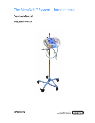
The MetaNeb™ System-International Service Manual Product No. PMN4XX
187293 REV 2
2015 by Hill-Rom Services PTE Ltd. ALL RIGHTS RESERVED. Manufactured by: HILL-ROM SERVICES PRIVATE LIMITED 1 YISHUN AVENUE 7 SINGAPORE 768923 Authorized European Union Representative: HILL-ROM SAS B.P. 14 - Z.I. DU TALHOUET 56330 PLUVIGNER FRANCE tel: +33 (0)2 97 50 92 12 No part of this text shall be reproduced or transmitted in any form or by any means, electronic or mechanical, including photocopying, recording, or by any information or retrieval system without written permission from Hill-Rom Services PTE Ltd. (Hill-Rom). The information in this manual is confidential and may not be disclosed to third parties without the prior written consent of Hill-Rom. The information in this manual is subject to change without notice. Hill-Rom makes no commitment to update or keep current, the information contained in this manual. Hill-Rom reserves the right to make changes without notice in design, specifications, and models. The only warranty Hill-Rom makes is the express written warranty extended on the sale or rental of its products. The MetaNeb™ System product may be covered by one or more patents. For a list of applicable patents, go to www.hill-rom.com/patents. This manual (187293) was originally released and supplied in English. For a list of available translations, contact Hill-Rom Technical Support. Second Edition, September 2015 First Printing, September 2014 MetaNeb™ is a trademark of Comedica, Inc. Hill-Rom® is a registered trademark of Hill-Rom Services, Inc. Replace this manual (187293) if it is damaged and/or can not be read. For product support or to order additional copies of this manual (187293), contact your distributor, local Hill-Rom representative, or go to www.hill-rom.com. The MetaNeb™ System-International Service Manual (187293 REV 2)
Page i
Reference Documents MetaNeb™ System User Manual (174432) MetaNeb™ System-183808 (Stand) Assembly (182920)
Page ii
The MetaNeb™ System-International Service Manual (187293 REV 2)
Table of Contents Chapter 1: Introduction Purpose... 1 - 1 Audience... 1 - 1 Reference Documents... 1 - 1 Document Symbols... 1 - 2 Model Identification... 1 - 3 Safety Tips... 1 - 3 Warning and Caution Labels... 1 - 4 Chapter 2: Troubleshooting Procedures Getting Started... 2 - 1 Pre-Use Check... 2 - 2 Rapid Problem/Solution Table... 2 - 3 Chapter 3: Theory of Operation Introduction... 3 - 1 Controller... 3 - 1 Chapter 4: Removal, Replacement, and Adjustment Procedures Tool and Supply Requirements... 4 - 1 Caster... 4 - 2 O-Rings... 4 - 3 Inlet Filter... 4 - 4 Removal... 4 - 4 Replacement... 4 - 5 Manometer Window... 4 - 6 Removal... 4 - 6 Replacement... 4 - 6 Adjust the Manometer to Zero... 4 - 7 Assemble the Oxygen Supply Hose (for country specific application)... 4 - 8
The MetaNeb™ System-International Service Manual (187293 REV 2)
Page iii
Chapter 5:Parts List Service Parts Ordering... 5 - 1 Exchange Policy... 5 - 3 In-Warranty Exchanges... 5 - 3 Out-of-Warranty Exchanges... 5 - 3 Recommended Spare Parts... 5 - 5 Controller and Stand... 5 - 6 Circuit... 5 - 8 Oxygen Supply Hose Assembly... 5 - 9 Chapter 6: General Procedures Clean and Disinfect... 6 - 1 Clean... 6 - 2 Disinfect... 6 - 2 Equipment Inspection... 6 - 3 Inspection Schedule... 6 - 4 Inspection Checklist... 6 - 5
Page iv
The MetaNeb™ System-International Service Manual (187293 REV 2)
Chapter 1 Introduction Purpose This manual gives the correct operation and service procedures for The MetaNeb™ System. It also gives a parts lists (in chapter 5) to order replacement components.
Audience This manual is intended for use by only facility-approved persons. Failure to obey this restriction can cause injury to people and damage to the equipment.
Reference Documents For more data (such as operation instructions, features, product symbols, and specifications), refer to The MetaNeb™ System User Manual (174432).
The MetaNeb™ System-International Service Manual (187293 REV 2)
Page 1 - 1
1
Document Symbols Chapter 1: Introduction
Document Symbols This manual contains different typefaces and symbols to make the content easier to read and understand: • Standard text-used for regular data. • Boldface text-emphasizes a word or phrase. • NOTE:-sets apart special data or important instruction clarification. • WARNING or CAUTION
Page 1 - 2
–
A WARNING identifies situations or procedures that can have an effect on patient or user safety. To ignore a warning could cause patient or user injury.
–
A CAUTION identifies special procedures or precautions that persons must obey to prevent equipment damage.
The MetaNeb™ System-International Service Manual (187293 REV 2)
Model Identification Chapter 1: Introduction
Model Identification Model Number a
PMN4XX
Description The MetaNeb™ System
a. XX is a placeholder for the country code.
Safety Tips WARNING: Only facility-approved service persons should service The MetaNeb™ System. Injury or equipment damage could occur. WARNING: Keep the unit in a dry environment, and do not permit moisture or liquid to pool on the unit. Injury or equipment damage could occur. WARNING: Use only with hospital grade 50 psi oxygen sources that meet local, state, and government regulations. CAUTION: Do not use harsh cleaners, solvents, or detergents. Equipment damage could occur.
The MetaNeb™ System-International Service Manual (187293 REV 2)
Page 1 - 3
1
Warning and Caution Labels Chapter 1: Introduction
Warning and Caution Labels
186180 174471
173269
Page 1 - 4
186183
The MetaNeb™ System-International Service Manual (187293 REV 2)
Chapter 2 Troubleshooting Procedures
2 Getting Started Do one of these: •
To isolate or identify a problem, go to “Pre-Use Check” on page 2-2.
•
If a problem is known, go to “Rapid Problem/Solution Table” on page 2-3.
Do the repair analysis procedure (RAP) or a component replacement shown for the problem. To make sure the repair corrected the problem, do the Pre-Use Check. If troubleshooting procedures do not identify the problem, contact your distributor or local Hill-Rom representative.
The MetaNeb™ System-International Service Manual (187293 REV 2)
Page 2 - 1
Pre-Use Check Chapter 2: Troubleshooting Procedures
Pre-Use Check Do this before each use: 1. Connect the gas hose to a 50 psi oxygen source. 2. Connect the circuit to the controller.
3. Set the mode to CHFO, and select Higher. 4. Turn the selector ring on the handset to three dots.
Higher
5. Turn the master switch ON. 6. Occlude the patient opening of the handset. 7. Watch the pressure gauge. The average of pressure fluctuations should not be less than 15 and not more than 30 cm H2O. 8. Set the mode to CPEP.
Lower
9. Turn the CPEP flow adjuster counterclockwise to full flow. 10. With the selector ring at three, occlude the patient opening of the handset and monitor the manometer. Make sure there is a peak pressure occurrence of not less than 20 and not more than 30 cm H2O. 11. If the device is not within the parameters specified above, do not use the unit. Contact your distributor or local Hill-Rom representative to examine and repair the unit.
Page 2 - 2
The MetaNeb™ System-International Service Manual (187293 REV 2)
Rapid Problem/Solution Table Chapter 2: Troubleshooting Procedures
Rapid Problem/Solution Table Problem Examine Repair Circuit will not connect cor- Examine the O-rings. Replace the O-rings rectly Examine the connector port. Replace the unit if port is damaged. Circuit will not function. Circuit not connected. Disconnect the circuit, and connect correctly. Leak in interface tubing. Replace the circuit. O-rings worn or missing. Replace the O-rings.
CHFO or CPEP therapy weak.
On/Off switch position. Filter inside oxygen hose connector on back of unit.
Make sure the switch is On. Replace the filter if dirty.
Connected to an approved 50 psi oxygen source.
Connect to an approved 50 psi oxygen source.
Selector ring is on the single Adjust the selector ring to dot setting. the 2 or 3 dot for the applicable effect. CPEP flow knob. Turn the CPEP flow knob to the applicable setting. No pulsations/flow. Mode, On/Off switch. Make sure the Mode selector switch and the On/Off switch are in the correct position. Unit DISS connection. Make sure the unit is connected to an approved 50 psi oxygen source. Connect the nebulizer corNebulizer not aerosolizing Nebulizer connection. rectly. correctly. Nebulizer is dirty. Clean or replace the nebulizer (see the Nebulizer package for cleaning instructions). Manometer shows a reading Go to “Adjust the Manomeeven though no pressure is ter to Zero” on page 4-7. applied.
The MetaNeb™ System-International Service Manual (187293 REV 2)
Page 2 - 3
2
Rapid Problem/Solution Table Chapter 2: Troubleshooting Procedures
NOTES:
Page 2 - 4
The MetaNeb™ System-International Service Manual (187293 REV 2)
Chapter 3 Theory of Operation Introduction The MetaNeb™ System is indicated for the mobilization of secretions, lung expansion therapy, the treatment and prevention of pulmonary atelectasis, and also has the ability to provide supplemental oxygen when used with compressed oxygen gas. The MetaNeb™ System can administer three types of therapy modes: • Continuous Positive Expiratory Pressure (CPEP)-the system supplies medicated aerosol combined with continuous positive pressure to help hold open and expand the airways. • Continuous High Frequency Oscillation (CHFO)-this is a pneumatic form of chest physiotherapy that delivers medicated aerosol while oscillating the airways with continuous pulses of positive pressure. • Aerosol-this is for the delivery of aerosol only. There are three components to the system: • Controller • Air supply hose • Disposable single patient use (SPU) circuit
Controller The controller has an input air supply connection, a user interface, a master On/Off switch, an internal regulator, pneumatic control circuitry, an oscillatory valve, and an output connection point for the SPU circuit. • Input air supply connection-an air supply hose permits the controller to be connected directly to the facility’s compressed oxygen gas supply. • User interface-shows status information and permits the user to input commands that control the operation of the system. • Master On/Off switch-controls the flow of incoming oxygen gas into the controller; the flow is either off or on. The MetaNeb™ System-International Service Manual (187293 REV 2)
Page 3 - 1
3
Controller Chapter 3: Theory of Operation
• Internal regulator-regulates the flow and pressure of the incoming oxygen gas into a range that can be used for both therapy modes and the nebulizer supply line. • Pneumatic control circuitry-determines the mode of operation and the flow level for CPEP mode. • Oscillatory valve-generates the pulses and determines the frequency used for CHFO therapy mode. • Output connection point (tri-connector port)-permits the disposable (SPU) to connect to the controller. The tri-connector port aligns the three supply lines (manometer feedback, nebulizer supply, and therapy) to the unit by means of the tri-filter and its mating tri-connector port. The three lines connect to the patient handset.
Page 3 - 2
–
The manometer feedback line transmits pressure readings from the front end of the handset to the controller and manometer. The manometer shows the average peak pressure in the handset.
–
The nebulizer supply line connects to the nebulizer via a universal connection bushing, and the nebulizer connects directly to the handset. The air pressure and flow supplied by the nebulizer line causes the liquid contents of the nebulizer cup to be aerosolized directly into the handset.
–
The therapy line connects to the back of the handset at the jet port. The therapy gas flows into the jet and is concentrated to the opening of the internal venture in the handset body. The venture pulls in the aerosol from the nebulizer and the outside air through the entrainment ports on the back of the handset jet and amplifies the airflow to the front of the handset. The venture also regulates the amplification of the flow based on the back pressure in the front of the handset. The mouthpiece or other respiratory fitting acts as the interface to the patient and permits the therapy air and aerosol to get to the patient lungs.
The MetaNeb™ System-International Service Manual (187293 REV 2)
Chapter 4 Removal, Replacement, and Adjustment Procedures Tool and Supply Requirements • Heavy-duty ferrule crimp tool • Rubber mallet • Small screwdriver • Small blade screwdriver • Tubing cutter • 7/8" open-end wrench
4
• 3/16" hex wrench
The MetaNeb™ System-International Service Manual (187293 REV 2)
Page 4 - 1
4.1 Caster Chapter 4: Removal, Replacement, and Adjustment Procedures
4.1
Caster Tools required:
Screwdriver Rubber mallet
Removal 1. Remove the controller from the pole. 2. Turn the stand upside down. 3. Remove the caster (A) from the arm (B) (see figure 4-1 on page 4-2). Figure 4-1. Caster
Replacement 1. Do the Removal procedure in reverse order. 2. Tap on the caster to make sure it is seated correctly.
Page 4 - 2
The MetaNeb™ System-International Service Manual (187293 REV 2)
4.2 O-Rings Chapter 4: Removal, Replacement, and Adjustment Procedures
4.2
O-Rings Tools required:
Small blade screwdriver
Removal 1. Disconnect the circuit from the controller. 2. Remove the O-ring(s) (A) from the circuit tri-connector port (B) (see figure 4-2 on page 4-3). Figure 4-2. O-rings
4
Replacement WARNING: Do not use any lubricants on the O-rings. Injury could occur. 1. Do the Removal procedure in reverse order. NOTE: Make sure the new O-rings are not damaged before you put the unit into service. 2. Do the “Pre-Use Check” on page 2-2. The MetaNeb™ System-International Service Manual (187293 REV 2)
Page 4 - 3
4.3 Inlet Filter Chapter 4: Removal, Replacement, and Adjustment Procedures
4.3
Inlet Filter Tools required:
3/16" hex wrench
Removal 1. Remove the controller from the pole. 2. Remove the oxygen supply line from the controller. 3. Use the hex wrench (A) to remove the inlet assembly (B) (see figure 4-3 on page 4-4). 4. Remove the spring (C), filter (D), and O-ring (E). Figure 4-3. Inlet Filter
Page 4 - 4
The MetaNeb™ System-International Service Manual (187293 REV 2)
4.3 Inlet Filter Chapter 4: Removal, Replacement, and Adjustment Procedures
Replacement WARNING: Do not use any lubricants on the O-rings. Injury could occur. 1. Install the O-ring (E), filter (D), and spring (C). 2. Install the inlet assembly (B). 3. Tighten the inlet assembly (B). 4. Do the “Pre-Use Check” on page 2-2.
4
The MetaNeb™ System-International Service Manual (187293 REV 2)
Page 4 - 5