Service Manual
122 Pages
Preview
Page 1
PROPRIETARY AND CONFIDENTIAL DRAFT March 08, 2017
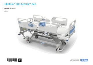
Hill-Rom® 900 Accella™ Bed Service Manual LI900B4
Rev.2 196238 *196238*
EN
PROPRIETARY AND CONFIDENTIAL DRAFT March 08, 2017 Hill-Rom® and Hill-Rom® 900 Accella™ are registered trademarks of Hill-Rom Services, Inc. Hill-Rom S.A.S. ZI du Talhouët 56330 PLUVIGNER - FRANCE Tel: + 33 (0)2 97 50 92 12 Fax: + 33 (0)2 97 50 92 03 www.hill-rom.com
2 3
Edition 2: March 2017 First printing 2016 Printed in Europe
The information contained in this manual is confidential and may not be reproduced or divulged in any form or by any means without the prior written permission of Hill-Rom. Hill-Rom reserves the right to make changes to the design, characteristics and models without prior notice. The only warranty Hill-Rom makes is the express written warranty extended on the sale or rental of its products. To order copies of this manual, refer to the last page, identify your national Hill-Rom representative and order the article with the part number 196238. © 2017 by Hill-Rom Services, Inc. ALL RIGHTS RESERVED.
Hill-Rom® 900 Accella™ Bed (LI900B4) Service Manual - 196238(2)
Allen® is a registered trademark of Industrial Fasteners, Inc. Loctite® is a registered trademark of Loctite Corporation, Inc. Torx® is a registered trademark of Textron, Inc. Truarc® is a registered trademark of Waldes Truarc, Inc.
PROPRIETARY AND CONFIDENTIAL DRAFT March 08, 2017
Table of Contents Chapter 1 : Introduction - description Introduction... 1 - 1 Applications... 1 - 1 Bed model and country of use... 1 - 1 Typographical conventions used in this manual... 1 - 1 Precautions for use... 1 - 2 Electrical safety precautions... 1 - 2 Abbreviations... 1 - 2 General description... 1 - 3 Warranty... 1 - 3 Accessories... 1 - 3 Symbols on the control units... 1 - 3 Standard functions... 1 - 4 Electrical function management... 1 - 4 HiLow... 1 - 4 Translation adjustable head section... 1 - 4 Head section CPR function... 1 - 4 Brakes... 1 - 4 Standard steering... 1 - 4 Endboards... 1 - 4 Hard surfaces... 1 - 4 Bumpers... 1 - 4 IV pole and patient helper receptacles... 1 - 4 Accessory support and bottle holder support pins... 1 - 4 Articulated sections of the sleep surface... 1 - 5 Autocontour function... 1 - 5 Trendelenburg/Reverse Trendelenburg... 1 - 5 Half-siderails... 1 - 5 Casters... 1 - 5 Sleep surface and weigh system... 1 - 5 Batteries... 1 - 5 Available functions depending on your bed model*... 1 - 6 Hill-Rom® 900 Accella™ Bed (LI900B4) Service Manual - 196238(2)
Bilateral HiLow pedal*... 1 - 6 “Bed connected to mains power, brake not applied” detection*... 1 - 6 Linen holder*... 1 - 6 Extension*... 1 - 6 Bilateral brake pedals at the head*... 1 - 6 Specifications... 1 - 6 General precautions for the place of use... 1 - 7 Precautions for transport and storage... 1 - 7 Electrical description... 1 - 8 Electric Control Unit... 1 - 8 Power-driven actuators... 1 - 10 “Bed connected to mains power, brake not applied” detection*... 1 - 10 Siderail keypads... 1 - 10 Graphical Caregiver Interface (GCI)®... 1 - 10 Weigh system... 1 - 10 Fault indicator Service required... 1 - 10 Night lights... 1 - 10 Head of Bed (HOB)... 1 - 11 Overview... 1 - 11 Configurations and wiring diagrams... 1 - 11 Regulatory requirements... 1 - 13
Chapter 2 : Troubleshooting procedures Getting Started... 2 - 1 Appendix... 2 - 1 Initial actions... 2 - 4 Final actions... 2 - 4 Quick problem identification/solution tables... 2 - 4 Operational checks... 2 - 5 None of the functions work... 2 - 8 The CSKs' lock-out LEDs flash when a button is pressed... 2 - 9 The bed's HiLow cannot be operated using the CSK... 2 - 10 The bed's HiLow cannot be operated using the HiLow foot controls... 2 - 11 Page 1
2 3
PROPRIETARY AND CONFIDENTIAL DRAFT March 08, 2017
2 3
The head section does not rise... 2 - 12 The head section does not descend... 2 - 13 Inoperative thigh section raise/lower function... 2 - 14 The Autocontour function is inoperative... 2 - 15 The manual CPR function is inoperative... 2 - 16 The electric CPR function is inoperative... 2 - 17 Inoperative electric Trendelenburg/Reverse Trendelenburg... 2 - 18 Chair position / Return to flat position / Bed exit Boost™ inoperative... 2 - 19 Night light inoperative... 2 - 20 The bed does not work with the battery... 2 - 21 Nurse call function does not work from a CSK... 2 - 22 Defective brake alarm... 2 - 23 Faulty brake function... 2 - 25 Faulty steering... 2 - 26 Weigh calibration error GCI... 2 - 27 Bed Incline Error GCI... 2 - 28 GCI error when weighing patient... 2 - 29 Weight out of weighing range error GCI... 2 - 30 HOB incline error GCI in main menu... 2 - 31
Chapter 3 : Part removal, replacement and adjustment procedures Preamble... 3 - 1 Appendix... 3 - 1 Symbols... 3 - 2 Position of casters... 3 - 3 Securing and locking out the electrical functions... 3 - 3 Accessing the power supply unit and securing against electric shocks... 3 - 4 Replacing the hard surfaces of the HS, LS, TS and FS... 3 - 5 Replacing the power cable... 3 - 6 Replacing the batteries... 3 - 7 Replacing the transformer... 3 - 8 Replacing the PSMB... 3 - 9 Replacing the MCB... 3 - 10 Replacing the NCB... 3 - 11 Replacing the ICB... 3 - 12 Replacing the SCB... 3 - 13 Replacing the brake alarm... 3 - 14 Page 2
Replacing the HiLow pedal*... 3 - 15 Replacing a HiLow motor... 3 - 16 Replacing a motor cord... 3 - 17 Replacing the CPR switch... 3 - 18 Replacing the adjustable head section CPR cables... 3 - 19 Replacing the AHS motor... 3 - 20 Replacing the adjustable thigh section motor... 3 - 21 Replacing the adjustable foot section racks... 3 - 22 Replacing the head section... 3 - 23 Replacing the foot section and/or the thigh section... 3 - 24 Replacing the brake/steer bar... 3 - 25 Replacing the casters, the brake caster and the steering caster... 3 - 27 Replacing the 5th self-steering wheel... 3 - 29 Replacing the extension or fixed end and/or linen holder... 3 - 30 Replacing the foot and headboard supports... 3 - 31 Replacing the head half-siderail assembly... 3 - 32 Replacing the foot half-siderail assembly... 3 - 33 Replacing the head half-siderail... 3 - 34 Replacing the foot half-siderail... 3 - 35 Replacing the head half-siderail mechanism... 3 - 36 Replacing the foot half-siderail mechanism... 3 - 37 Replacing the damper actuator of the head or foot half-siderail... 3 - 38 Replacing the head half-siderail control... 3 - 39 Replacing the accelerometer... 3 - 40 Replacing the GCI... 3 - 41 Replacing the HIB/GCI cable... 3 - 42 Replacing the load beam... 3 - 43 Replacing the buzzer... 3 - 44 Replacing the night light... 3 - 45 Replacing the nurse call cable... 3 - 46
Chapter 4 : General procedures Cleaning and care... 4 - 1 General Cleaning... 4 - 1 Dry steam cleaning... 4 - 1 Hard to Clean Spots... 4 - 1 Disinfection... 4 - 1 Hill-Rom® 900 Accella™Bed (LI900B4) Service Manual - 196238(2)
PROPRIETARY AND CONFIDENTIAL DRAFT March 08, 2017 Storing the bed... 4 - 1 Lubrication requirements... 4 - 2 Preventive maintenance... 4 - 2 Preventive Maintenance Schedule... 4 - 2 End-of-life equipment... 4 - 6
Chapter 5 : Calibration/weighing check procedure and HOB Introduction... 5 - 1 Definitions... 5 - 1 Equipment required... 5 - 1 Display modes... 5 - 1 USER mode... 5 - 1 HIGH RESOLUTION mode... 5 - 2 Weigh system check procedure... 5 - 2 Preparation of the bed... 5 - 2 Gravity constants... 5 - 3 Calibration... 5 - 4 Repeatability test... 5 - 6 Offset test... 5 - 7 Weighing test... 5 - 7 Reset accuracy... 5 - 8 Indication limit test... 5 - 8 Tare precision... 5 - 9 Final operations... 5 - 9 Adjustable head section angle calibration... 5 - 9
Hill-Rom® 900 Accella™ Bed (LI900B4) Service Manual - 196238(2)
2 3
Page 3
PROPRIETARY AND CONFIDENTIAL DRAFT March 08, 2017
2 3
Page 4
Hill-Rom® 900 Accella™Bed (LI900B4) Service Manual - 196238(2)
PROPRIETARY AND CONFIDENTIAL DRAFT March 08, 2017
Chapter 1 Introduction - description Introduction This manual contains the information required for the normal operation and maintenance of the Hill-Rom® 900 Accella™ Bed. The part numbers of the spares can be found in the spare parts list, P/N 196237. This manual is intended for use by facility-authorized personnel. Use by unauthorized personnel may result in damage to the equipment and/or serious injury to staff or users.
Applications Hill-Rom® 900 Accella™ LI900B4 hospital beds with CPR are beds for intensive care (the CPR function remains operational in the event of a mains power failure) acute care or outpatient (ambulatory) care for adult patients (EN60601-2-52 application environments 1, 2 and 5).
Bed model and country of use Certain bed features may be available or not, depending on the destination country. These features are identified with an asterisk (*). To identify your bed model and serial number (HRP000000) and its date of manufacture, refer to the identification label (See “Overview” page 1 - 11). Your bed (reference LI900B4) is composed of a chassis/sleep surface (reference CS900B4) and two endboards, a headboard and a footboard.
Typographical conventions used in this manual This manual contains different typefaces and icons designed to improve readability and increase understanding of its content. Note the following examples: • Normal: used for regular information. • Bold: emphasizes a word or phrase. • NOTE: highlights special information or explains an important instruction. • The symbols below represent different risks or hazards:
CAUTION:
1 2
The WARNING symbol identifies situations or actions that may affect patient or user safety.
WARNING: The CAUTION A symbol points out special procedures or precautions that G personnel must follow to avoid equipment damage.
ELECTRIC SHOCK HAZARD: The “ENTRAPMENT WARNING” symbol informs users of risks of entrapment if the warning is not heeded.
3
ENTRAPMENT WARNING: CS900B4XXXXXX: CS900 = Hill-Rom® 900 Accella™; B = version; 4XXXXXX = unique 7-figure numerical code according to different criteria such as the voltage, the electrical functions, the language, etc. HRPXXXXXXX: HRP = Hill-Rom Pluvigner; XXXXXXX = incremental code.
Hill-Rom® 900 Accella™ Bed (LI900B4) Service Manual - 196238(2)
The “ELECTRIC SHOCK HAZARD” symbol informs users of risks of electric shock if the warning is not heeded.
4 Page 1 - 1
PROPRIETARY AND CONFIDENTIAL DRAFT March 08, 2017 Precautions for use Chapter 1: Introduction - description
Precautions for use CAUTION: Use of the bed's functions may result in serious bodily harm. The bed's functions must only be used by trained and knowledgeable staff. The articulation functions of the bed can be stopped by releasing the control, while pressing and holding the switch of the opposite control or by disconnecting the power supply connector.
2
Before using the bed, read and understand the contents of the User Manual of the Hill-Rom® 900 Accella™ Bed LI900B4 and of this manual. It is also important to understand and strictly observe all the safety instructions in these manuals.
ENTRAPMENT WARNING: Users of this equipment are potentially exposed to electric shocks. Always train and inform staff of the risks inherent in electrical equipment.
3
The electric circuit is mechanically isolated from the metal parts of the bed. Preparations for use: • only connect the bed to a mains electric power supply with a protective earth (see “Electrical safety precautions” page 7), • the power plug must be accessible for disconnecting the bed, • wait 12 hours until the battery is fully charged before using the bed without the mains power supply, • make sure that all the moving parts are in good working order,
Electrical safety precautions The mains power supply for the bed must comply with following standards: • NF C 15-100 and NF C 15-211 (France) • International Electrotechnical Commission (IEC) 364 for other locations. Check that the bed’s power requirements on the identification label (See “Overview” page 1 - 11) correspond to the hospital's power supply voltage. The power supply should be equipped with a maximum 30 mA earth leakage circuit breaker, in compliance with IEC 364-5-53.
Page 1 - 2
Abbreviations Abbreviations AFS AHS ALS ATS CAN CPR CSK DCG DMM ECU EOT FS FS GCI HFC HIB HL HOB HS ICB IVP MCB NC NCB NO P/N PAT PPM PSK PSMB RAP S/A SCB T/RT TAHS TS VAC VDC WC
Definition Adjustable foot section (function) Adjustable head section (function) Adjustable leg section (function) Adjustable thigh section (function) Controller Area Network Head section “CPR” Caregiver Siderail Keypad Duty Cycle Guard Digital multimeter Electric Control Unit End of travel Foot section Foot section Graphical Caregiver Interface HiLow Foot Control Human Interface Board HiLow Head Of Bed Head section Interface Control Board IV pole Motor Control Board Normally closed Nurse Call Board Normally open Part number Portable appliance tester Patient Position Monitoring Patient Siderail Keypad Power Supply Management Board Repair and analysis procedure Subassembly Scale Control Board Trendelenburg/Reverse Trendelenburg Translation adjustable head section Thigh section Volts, alternating current Volts, direct current Weigh Cell
Hill-Rom® 900 Accella™ Bed (LI900B4) Service Manual - 196238(2)
PROPRIETARY AND CONFIDENTIAL DRAFT March 08, 2017 General description Chapter 1: Introduction - description
General description The operation of the Hill-Rom® 900 Accella™ Bed can be split into two subsystems: • Mechanical • Electrical Electrical functions: • HiLow: raise/lower sleep surface. • Adjustable head section: raise/lower. • Adjustable thigh section: raise/lower. • Trendelenburg/Reverse Trendelenburg Mechanical functions: • Adjustable foot section. The Hill-Rom® 900 Accella™ Bed is equipped with a battery. Installation of this battery is mandatory with the electric T/RT. The electrically-controlled functions can be accessed by the patient or caregiver using the controls built into the half-siderails or the bilateral HiLow pedal*.
Warranty
Symbols on the control units Figure 1-1. Bilateral HiLow pedal*
1
Lock control under the pedal* (for use by caregivers only)
Figure 1-2. Half-siderail keypads
1
Caregiver keypad Bed not in lowered position indicator
Nurse call activator Battery charge status LED.
45°
2
Fault indicator light. Service required. Night light*(1)
NOTE:
The warranty is automatically annulled if any electrical component of the bed is opened, apart from if the cover of the power supply unit is opened by an authorized person.
CPR Lock control(1)
Boost™ system
Accessories The list of accessories that can be used with the Hill-Rom® 900 Accella™ Bed can be found in the User Manual.
3
Patient keypad
CAUTION: Only the accessories specifically identified below are authorized to be used on the Hill-Rom® 900 Accella™ Bed.
4
Nurse call activator
45°
1. Functions available only to the caregiver.
Hill-Rom® 900 Accella™ Bed (LI900B4) Service Manual - 196238(2)
Page 1 - 3
PROPRIETARY AND CONFIDENTIAL DRAFT March 08, 2017 Standard functions Chapter 1: Introduction - description
Standard functions Electrical function management The electrical functions are managed by controls built into the half-siderails. They are used to disable and enable the electrical functions.
HiLow
2
The HiLow system is made up of two independent oscillating elevation arms that are articulated on the bed frame and slide into the sections of the chassis. The motors are attached to the bed frame and to the elevation arm.
Translation adjustable head section The AHS function combines the upwards and sideways movements of the head section towards the head of the bed. These combined movements increase the sitting surface for greater patient comfort when seated.
NOTE:
3
The bed is fitted with an angular marker for the head section that is built into the slider system.
Head section CPR function The Hill-Rom® 900 Accella™ Bed features a CPR function for the head section for cardio-pulmonary resuscitation. CPR handle The yellow CPR handles on either side of, or under, the head section are used to disengage the driving gear located inside the adjustable head section motor. The head section then descends by gravity. The movement is assisted and cushioned by the actuator until the section reaches the rubber stop on the bed frame. This automatically levels the bed's HiLow with the highest side CPR button This function is activated by pressing and holding the CPR button on the caregiver half-siderail keypads. This returns all sections of the sleep surface to the flat position and levels the bed frame with the lowest side.
Brakes The Hill-Rom® 900 Accella™ Bed has a central braking system that is controlled by a single brake bar. The brakes are applied simultaneously to the four casters by a hexagonal bar at the foot of the bed that controls two linkage bars in each section of the chassis, which actuate a hexagonal bar on each side of the head end of the bed. The brake bar is directly mounted on the foot end hexagonal bar of the bed.
Standard steering The Hill-Rom® 900 Accella™ Bed features a steering function for easier handling when moving the bed or transferring a patient. The steering caster on the right-hand side at the head of the bed (as seen by the patient) or on the lefthand side at the head of the bed* can be locked in the longitudinal axis of the bed by raising the brake bar.
Endboards The Hill-Rom® 900 Accella™ Bed is fitted with headboards and footboards. These endboards can be extracted vertically. They make the bed easier to move and steer thanks to the built-in handles. The boards are also fitted with sleeves for quick installation on the cross members at the head and the foot of the bed. The headboard and footboard are not interchangeable.
Hard surfaces The articulated hard surfaces are made of thick laminate. They can be removed and attached using a system of clips.
Bumpers The protective stops are positioned on the four corners of the bed frame on beds with mobile headboards. On fixed headboards: two at the foot of the frame and two at the head of the chassis.
IV pole and patient helper receptacles The Hill-Rom® 900 Accella™ Bed has four receptacles (two at the head end and two at the foot end) for IV poles. The two receptacles at the head end can also be used to install a patient helper.
Accessory support and bottle holder support pins The Hill-Rom® 900 Accella™ Bed is fitted with eight accessory support pins (Hill-Rom accessories, drainage bags, etc.). They are located on either side of the middle and rear sections of the bed beneath the sleep surface. Page 1 - 4
Hill-Rom® 900 Accella™ Bed (LI900B4) Service Manual - 196238(2)
PROPRIETARY AND CONFIDENTIAL DRAFT March 08, 2017 Standard functions Chapter 1: Introduction - description
Articulated sections of the sleep surface The sleep surface of the Hill-Rom® 900 Accella™ Bed is made up of three articulated sections: the adjustable head section, the adjustable thigh section and the mechanical adjustable foot section. Two racks are used to adjust the angle of the AFS.
Autocontour function The Autocontour function prevents the patient from sliding towards the foot of the bed when the head section is raised. When the raise HS function is activated, the head section is raised from the horizontal position, and then the head and thigh sections are raised simultaneously after 5 seconds. The thigh section rises to the fully raised position (28°) and the head section continues its movement. When the lower HS is activated, the head section is raised and the sections then descend simultaneously after 5 seconds. The thigh section descends to its lowered position and the head section continues its movement.
NOTE:
The Autocontour function is disabled if the ATS is locked.
Trendelenburg/Reverse Trendelenburg The sleep surface can be titled in two ways: – Reverse Trendelenburg: foot end in low position. – Trendelenburg: the head end is lowered The maximum angle for Trendelenburg/Reverse Trendelenburg is available at all heights of the sleep surface.
NOTE:
This function can be used without a mains power supply thanks to the battery.
NOTE:
A spirit level is built into the foot half-siderails to indicate the angle of the sleep surface in relation to the horizontal plane.
Half-siderails The head half-siderails are attached to the head section and are equipped with control keypads used to manage the bed's electrical functions. The foot half-siderails are attached to the bed frame.
Hill-Rom® 900 Accella™ Bed (LI900B4) Service Manual - 196238(2)
The half-siderails can be placed in two positions (low and high). The halfsiderail audibly clicks into the high position for greater safety. They can be turned towards the exterior of the bed and the downward movement is damped by a gas actuator.
Casters The Hill-Rom® 900 Accella™ Bed is fitted with four swiveling casters at the four corners of the bed. The bed is fitted with four casters (three brake casters and one brake and steering caster), each with a 30° incline control mechanism and three positions: • Brake caster: Brake/Neutral/Neutral • Steer caster: Brake/Neutral/Steer The standard caster can be replaced with an anti-static brake caster. It is identified by a yellow dot on the tread (single band) or in the center of the caster (double band). It is located to the left of the sleep surface at the head end (if there is a steering caster at the foot end) or at the foot end (if there is a steering caster at the head end).
1 2
Sleep surface and weigh system The upper part of the bed is composed of a supporting structure and a mobile sleep surface suspended by articulated rods. The rods are connected to weigh cells that are attached to the supporting structure. The weigh cells operate using the principle of strain gage. Table 1-1. Characteristics of the electric bed's weigh system HillRom® 900 Accella™ Features Value Class of the weigh system (2014/31/EEC) NAWI Class III Maximum range of the weigh system 250 kg Minimum range of the weigh system 10 kg Scale 0.5 kg
3
a
a. (Non-Automatic Weigh Instrument)
Batteries The Hill-Rom® 900 Accella™ Bed is equipped with a battery so that the bed operates normally when being moved or in the event of a mains power failure. They operate fully automatically.
Page 1 - 5
4
PROPRIETARY AND CONFIDENTIAL DRAFT March 08, 2017 Available functions depending on your bed model* Chapter 1: Introduction - description
Available functions depending on your bed model*
Specifications L+
Bilateral HiLow pedal*
W
L
The Hill-Rom® 900 Accella™ Bed can be fitted with a bilateral HiLow pedal that caregivers can use to raise or lower the sleep surface. A paddle located beneath the pedal can be actuated with the top of the foot to lock and unlock the HiLow.
65° 28°
“Bed connected to mains power, brake not applied” detection*
2
H
The brakes must always be applied when the bed is connected to the mains power. Otherwise, caregivers will be reminded to obey this rule by a continuous beep. This safety device prevents damage to the mains power cord when moving he bed. The audible alarm stops when the brake is applied or when the bed is unplugged from the mains. Steering system with controlled 5 wheel* The 5 wheel facilitates movements of the Hill-Rom® 900 Accella™ Bed thanks to a central steering point beneath the chassis. The system is enabled and disabled using the brake bar or the head end brake pedal*.
C
B1
B2
th
th
3
S1
Linen holder* The Hill-Rom® 900 Accella™ Bed can be fitted with a linen holder that slides away under the frame. Once deployed, the linen holder can be used to hold sheets and blankets when making the bed. The safe working load is 15 kg.
Extension* The extension of the Hill-Rom® 900 Accella™ Bed is designed for tall patients. It significantly increases the overall length of the bed. The extension is locked in position by a system of notches and is actuated by a handle. Six positions are available from 0 to 20 cm at 4 cm intervals. An extension cushion, available as an accessory, can be used to extend the mattress when the extension is deployed.
Bilateral brake pedals at the head* The Hill-Rom® 900 Accella™ Bed can be fitted with bilateral brake pedals at the foot of the bed in addition to the brake bar.
h
Features Maximum width (W) Maximum length (without extension) (L) Maximum length (with extension closed) (L) Maximum length (with extension open) (L+) Length of the head half-siderail protection (B1) Length of the foot half-siderail protection (B2) Siderail protection height (without mattress) (S1) Low position (casters Ø150 mm diameter double band) (h) Low position (casters 150 mm ) (h) High position (casters 150 mm diameter double band) (H) High position (casters 150 mm diameter) (H) Chassis clearance (casters 150 mm diameter double band) (C) b
b
b b
b
Page 1 - 6
Value 995 mm 2162 mm 2180 mm 2380 mm 499 mm 631 mm 393 mm 431 mm 439 mm 800 mm 808 mm 195 mm a
a a a
a a a a a a a a
Hill-Rom® 900 Accella™ Bed (LI900B4) Service Manual - 196238(2)
PROPRIETARY AND CONFIDENTIAL DRAFT March 08, 2017 Specifications Chapter 1: Introduction - description
Features Chassis clearance (casters 150 mm diameter) (C) Head section incline Thigh section incline Foot section incline Trendelenburg/Reverse Trendelenburg Positioning system Boost™ b
c
c
c
c
Electric CPR - return head section to flat position (T1) and sleep surface (T2) Safe working load (SWL) Maximum patient weight LI900B4 bed weight (no mattress or accessories) Total authorized weight during movement Maximum temperature of the applied parts at 40°C Unweighted peak acoustic pressure levels Weighted maximum measured acoustic pressure
Value 203 mm + 65° + 28° - 3° to -22° + 17°/- 17° -7°/ 30 sec T1 < 5 s T2 < 30 s 250 kg 185-215 kg 170 kg 420 kg 56.5°C <120 dB 42 dBA a
a
Precautions for transport and storage The following conditions must be met to ensure that the bed and its accessories are shipped and stored in complete safety.
a
a. These are average values which may vary according to manufacturing tolerances. b. Dimensions in mm. c. Maximum incline in relation to the sleep surface d. SWL 250 kg / the maximum patient weight varies according to the mattress and accessories used - 185 kg according to EN60601-2-52 (intensive and acute care) - 215 kg according to EN60601-2-52 (outpatient [ambulatory] care).
a
a
d
During shipment , the bed must be - in the low position - in “functions locked” mode - covered, brakes applied and all moving parts secured - protected from fluid ingress a
When stored, the bed must be
1
- in the low position - in “functions locked” mode - covered, brakes applied - protected from fluid ingress
a. Shipment does not include the transfer of the bed between wards with or without patients.
Table 1-3. Environmental conditions for shipment and storage Condition Range Temperature
Between -30° and +50°C
Humidity
20% - 85%
Pressure
700 hPa<P<1060 hPa from 0 to 2000m
During shipment or storage, the beds should not be stacked one on top the other.
3
General precautions for the place of use Table 1-2. Operating environment Condition Range Temperature
Between +10° and +40°C
Humidity
30% - 85%
Pressure
700 hPa<P<1060 hPa from 0 to 2000m
2
4 Hill-Rom® 900 Accella™ Bed (LI900B4) Service Manual - 196238(2)
Page 1 - 7
PROPRIETARY AND CONFIDENTIAL DRAFT March 08, 2017 Electrical description Chapter 1: Introduction - description
Electrical description
Electric Control Unit
Table 1-4. Hill-Rom® 900 Accella™ Bed specifications Description Specifications
2 3
Type Part number Type of protection against electric shock (according to IEC 60601-1) Degree of protection against electric shock (according to IEC 60601-1) Protection provided by the covers (according to IEC 60529) Intermittent operation factor Voltage Frequency: Fuse rating on primary Maximum absorbed power
Bed LI900B4 Class I Type B IPX4 10% 2 min/18 min 120V AC 230V AC 60 Hz 50-60 Hz 2 x 2.0 A T 2 x 1.6 A T 500 VA 500 VA a
a. Do not operate electrical functions continuously for more than 2 minutes in any 18 minute period when the bed is loaded at the safe working load value as this may damage the electrical components. The power supply of the actuator is temporarily cut off if the load factor is exceeded when using the HiLow.
The Hill-Rom® 900 Accella™ Bed complies with the standard EN60601-252 (for more details, refer to “Regulatory requirements” page 1-13). All beds are tested prior to delivery, and grounding and equalization of potentials and current leaks are verified.
Page 1 - 8
The ECU is comprised of several main parts used for controlling and powering the bed's different functions: • one transformer. • one power supply board (PSMB). • one motor control board. (MCB) • one scale control board (SCB). • one interface control board (ICB). • one nurse call board (NCB). • batteries. • a connector for maintenance appliances (CAN). Transformer The power stage is made up of a transformer, protected at the input by two delayed fuses (see table 1-4 page 1-8), and a rectifier bridge and filter capacitor at the output. The output voltage of approximately 33 VAC is not regulated. Its voltage varies around 24 V DC, depending on the power requirement. The transformer is also protected by a non-resettable internal thermal protection for the 230V version and a resettable internal thermal protection for the 120V version. Power supply board (PSMB) The PSMB powers the MCB and the ICB. The board ensures that the back-up batteries and emergency functions are charged. The output power is used to control several function simultaneously. Motor control board (MCB) This board controls the bed's different electrical functions: HiLow, adjustable head and thigh sections with Autocontour, brake alarm, chair position, return to the flat position, bed exit and Boost™. It is powered by the ICB. The board is controlled by a microcontroller and controls the motors by relays. In order to protect these relays from electrical arcing during switching, an FET transistor that is common to all the outputs checks the power after a delay when a function is activated, allowing the relays to switch off. The input voltage of the motors is rectified and filtered. The input voltage of the PCBs is rectified, filtered and regulated.
Hill-Rom® 900 Accella™ Bed (LI900B4) Service Manual - 196238(2)
PROPRIETARY AND CONFIDENTIAL DRAFT March 08, 2017 Electrical description Chapter 1: Introduction - description
Scale control board (SCB) This is powered by the ICB and performs the following functions: • control of the system by microcontroller. • reading and analog-digital conversion of the weigh cell signals. • transfer of data to the displays. • detection of longitudinal and/or tilting of the sleep surface by +/- 2°. • data storage (weight, tare, etc.) in an EEPROM. • monitoring of the power supplies that reset the microcontroller in the event of a power supply problem. Interface control board (ICB) Controls the communications between the various boards and the connected systems, such as the graphical caregiver interface (GCI), the HiLow pedal, the brake alarm, the night light, the accelerometer (HOB), the patient position monitoring (PPM), the nurse call system, the loudspeaker and the connector for maintenance appliances (CAN). Nurse call board (NCB) The nurse call board transfers the alarm signals to the caregivers via HillRom's Navicare™ system. Connection (CAN) The bed features a socket for connecting a maintenance device. • All devices connected to this socket (CAN) must meet the requirements of IEC 60950-1. Batteries These batteries can be used to operate the bed's functions when the mains power supply is not available. The charging circuit in the power supply unit has a current limiter, according to the level of the battery charge. Charging begins as soon as the unit is connected to AC power. At the end of charging, the load current is very low. An audible low battery alarm buzzer sounds during movement if the battery voltage drops (a continuous beep heard each time a control is pressed). In addition, an LED on the caregiver's half-siderail keypads indicates the battery charge level.
Hill-Rom® 900 Accella™ Bed (LI900B4) Service Manual - 196238(2)
Table 1-5. Battery charge indicators Green battery LED: the batteries are sufficiently charged. Orange battery LED: the batteries need to be charged. Flashing orange battery LED + orange maintenance LED: the back-up and/or emergency batteries are discharged and must be recharged immediately. Battery LED off: the back-up battery is completely discharged.
+
Table 1-6. Characteristics of the battery Description Specifications Composition Capacity of each element Voltage Circuit breaker with fuse Maximum charging time Discharging time (storage), battery connected to bed Discharging time (storage), battery not connected to bed
three 12 V elements in a block 1.2 Ah min 24 V DC 10 AT - 250 V - cut-off capacity: 100 A@250 VAC 12 hours 3 months 3 months
The sealed lead acid batteries are series connected to the main PCB and protected by a fuse on the connecting wires. The battery type has no memory effect and can be charged regularly without any particular constraints. Recap of the memory effect: certain types of battery (Nickel Cadmium) must be fully discharged before being recharged. Disregarding this caution may cause significantly reduce their service life. Battery capacity after a full recharge with safe working load on the bed: One complete HiLow, HS, TS and T/RT raise/lower cycle before alarm, then one more complete cycle.
Page 1 - 9
1 2 3 4
PROPRIETARY AND CONFIDENTIAL DRAFT March 08, 2017 Electrical description Chapter 1: Introduction - description
Power-driven actuators
2 3
Siderail keypads
Four separate motor-driven actuators powered by the MCB are used to operate the bed’s different electrical functions. They are all designed to withstand the risks of ingress of liquids under normal conditions of use. The AHS and ATS actuators only operate in thrust mode. When the rod is retracted, the AHS and ATS can disengage to avoid the risk of entrapment between the section and the structure of the bed frame. The section is lowered by the weight of the head and thigh sections. This function is also used to raise the head section manually without actuating the CPR handle. The upper and lower internal end of travel stops (EOT), detected when the motors reach their end positions, are controlled by the MCB. All movements can only be made by pressing and holding the button of the corresponding function. (There are no automatic movements, except for the mechanical CPR (See “CPR handle” page 1 - 4)). Depending on the function, one button corresponds to the movement of one or more motors (Autocontour). Table 1-7. Motor characteristics HiLow motor Head section Description SWL 250 kg motor Absorbed power Voltage Intermittent service Center-to-center with rod extracted Center-to-center distance with rod retracted
Thigh section motor
100 VA 70 VA 75 VA 24 VCC 24 VCC 24 VCC 10% 10% 10% (2 min/18 min) (2 min/18 min) (2 min/18 min) 570 mm 700 mm 300 mm a
420 mm
b
a
a
b
236.5 mm
440 mm
b
a. (±4 mm) b. (±2 mm)
“Bed connected to mains power, brake not applied” detection* The detection system operates using a NF switch, mounted on the foot end crossbar that is activated by the hexagonal brake bar. The power supply unit triggers an audible alarm if the following two circumstances occur at the same time: presence of mains voltage and switch not activated. The audible alarm stops when the brake is applied or if the bed is unplugged from the mains. Page 1 - 10
The bed is fitted with two siderail keypads on either side of the head halfsiderails. • patient siderail keypad, • caregiver siderail keypad. Each of the siderail keypads is made up of a cup panel connected to an junction PCB, which in turn is connected to the ICB.
Graphical Caregiver Interface (GCI)® The graphical caregiver interface is made up of the screen and the HIB. It is used to control the various interfaces, such as the weigh system, the bed exit alerts, the adjustable head section angle alert and the user preferences and provides technicians with access for maintenance and calibration purposes.
Weigh system The four weigh cells are connected to the weigh PCB which permanently analyzes the incoming signals. The analyzed data is displayed on the siderail display (GCI) according to the user's actions.
Fault indicator Service required The indicator lights flash in the event of various faults. The cause of the fault can be: 1. A faulty component, 2. Battery low, 3. Micro-power cut, 4. A person sitting on the side of the bed. In case 2, refer to tableau 1-5 page 1-9. In case 3, press a key. In case 4, ask the person to stand up. If the indicator light still flashes, proceed with troubleshooting (See “Operational checks” page 2 - 5).
Night lights The night lights are under the electrical control unit. They can be switched on and off on the caregiver keypads. Once activated, the night light comes on and changes color according to the height of the sleep surface. • Green: the bed is in the low position. • Orange: the bed is not in the low position.
Hill-Rom® 900 Accella™ Bed (LI900B4) Service Manual - 196238(2)
PROPRIETARY AND CONFIDENTIAL DRAFT March 08, 2017 Overview Chapter 1: Introduction - description
Head of Bed (HOB)
Configurations and wiring diagrams
The accelerometer is under the head section. It displays the patient position monitoring (PPM) function and the angle of the head section.
F
NOTE:
The dotted lines in the following diagrams represent functions that can be added to the bed.
Overview B
The Hill-Rom® 900 Accella™ Bed can be fitted with bilateral HiLow pedals.
A
1
H
C
2
I J E
K D
M
G
L
Item
Name
Item
A B C
H I J
Footboard Extension + linen-holder* Bumper (4)
D
Half-siderails Headboard 2 sockets for I.V. pole and patient helper Caregiver half-siderail controls
K
E F
Head section “CPR” control Patient half-siderail controls
L M
Central brake and steer bar control Casters 150 mm diameter* Bilateral HiLow pedal with caregiver mode*
G
Graphical Caregiver Interface controls (GCI)™
3
Name
Hill-Rom® 900 Accella™ Bed (LI900B4) Service Manual - 196238(2)
4 Page 1 - 11
PROPRIETARY AND CONFIDENTIAL DRAFT March 08, 2017 Overview Chapter 1: Introduction - description Figure 1-3. Wiring of bed with half-siderails with built-in controls - all functions Nurse Call Control cable
Right CSK
Power supply board (PSMB)
CPR
Night lights
2
Right PSK Right foot weigh cell (P3)
Battery
Right head weigh cell (P4)
Scale control board (SCB) Transformer
3
Motor control board (MCB)
CAN*
Nurse call board (NCB)* Interface control board (ICB)
Loud speaker
AHS Screen (GCI)
Human Interface Board (HIB) Head of Bed (HOB)
left foot weigh cell (P2)
left head weigh cell (P1)
Head
ATS
HiLow foot control*
HiLow foot control*
Left CSK
Foot Brake alarm*
Page 1 - 12
Left PSK
Junction PCB for half-siderail keypads
Hill-Rom® 900 Accella™ Bed (LI900B4) Service Manual - 196238(2)
PROPRIETARY AND CONFIDENTIAL DRAFT March 08, 2017 Regulatory requirements Chapter 1: Introduction - description
Regulatory requirements NF MEDICAL “Hospital beds” compliant bed • Authorization no.: NF178-01/01
• and "NF Environnement - Ameublement" Institut Technologique FCBA 10, Rue Galiléeavenue de Saint-Mandé 77420 Champs-sur-Marne - FRANCE www.fcba.fr Certified characteristics: • electrical safety precautions, • electromagnetic compatibility, • mechanical safety precautions, • aptitude for use. Complies with standards: • NF-S-90-312 (1984), • EN-60601-1 (2007), • EN-60601-1-2 (2007), • EN 60601-2-52 (2010), application environments 1, 2 and 5. The CE mark was applied for the first time in 2016, in accordance with the essential demands of the directive 93/42/EEC applying to class I medical devices. The NF Environnement-certified Hill-Rom® 900 Accella™ bed is designed, manufactured and checked to reduce environmental impact up to end of life (limitation of transformation energy of the materials, heavy metal-free finishing products, possibility to recycle, etc.). INMETRO rule no. 350, September 06, 2010 and mandatory certification of electrical equipment under requirements of National Health Surveillance Agency - ANVISA - RDC no. 27, 2011-06-21 and IN 03, 2011-06-21. The bed's weigh system Hill-Rom® 900 Accella™ meets the requirements of directive 2014/31/EEC applying to class III NAWI (non automatic weight instruments).
Hill-Rom® 900 Accella™ Bed (LI900B4) Service Manual - 196238(2)
General Symbols Manufacturer
Date of manufacture
Product reference
Serial number
General safety sign
Equipotential terminal
Refer to the user manual
Type B equipment
DO NOT BIN, follow the local recycling regulations
Direct Current
Danger – Do not use
Alternating Current
Recyclable material
Earth leakage circuit breaker rating
Total authorized weight during movement
Body Mass Index ≥17
Patient weight ≥40 kg
Patient size ≥146 cm
Atmospheric pressure limits
Moisture content limits
Temperature limits
Maximum patient weight
Safety earth
Safe working load (SWL)
1 2
Page 1 - 13
3 4
PROPRIETARY AND CONFIDENTIAL DRAFT March 08, 2017 Regulatory requirements Chapter 1: Introduction - description
2
References of recommended
Do not store in the place shown
No oxygen tents
Compliant with Directive 93/42/EEC
Compliant with Directive 2014/31/EEC
NF MEDICAL “Hospital beds” compliant bed
Patient helper position
NF ENVIRONMENT compliant bed
mattresses Steam cleaning
Endboard lock label
Caster control
Function symbols
3
Head section (CPR)
Do not sit or climb on the linen holder*
Headboard position Latitude/altitude label
Ground continuity and current leak values
Metrological certification label of the weigh system
In-service check sticker
Do not sit or climb on the extension*
Label indicating non-weighed support
Page 1 - 14
Hill-Rom® 900 Accella™ Bed (LI900B4) Service Manual - 196238(2)