Technical Manual
111 Pages
Preview
Page 1
Faxitron X-Ray Corp. Date Jan. 1, 1996
Models 43855A, 43855B, 43856A Manual No. 5081-9519
TECHNICAL MANUAL Faxitron Cabinet X-ray Systems Models 43855A, 43855B and 43856A
CONTENTS
SECTION
General Information
1
Installation
2
Operation
3
Principles of Operation
4
Maintenance
5
Schematics
6
Part List
7
Radiation Survey
8
Maintenance Schedule
9
© Copyright Faxitron X-Ray Corporation 1983, 1984, 1986, 1987, 1989, 1990, 1994, 1996. This document contains or refers to proprietary information that is protected by copyright. All rights are reserved. Copying or other reproduction of this document is prohibited without the prior written permission of Faxitron X-Ray Corporation.
225 Larkin Drive Wheeling, Illinois 60090-7209, USA Telephone 847-465-9729 Fax 847-465-9740
Rev. 9
0.0
Faxitron X-Ray Corp. Date Jan. 1, 1996
Models 43855A, 43855B, 43856A Manual No. 5081-9519
REVISION RECORD
Rev.
9
From Serial No.
To (and incl.) Serial No.
43855A: 43855B: 43856A:
43855A: 43855B: 43856A:
10
43855A: 43855B: 43856A:
43855A: 43855B: 43856A:
11
43855A: 43855B: 43856A:
43855A: 43855B: 43856A:
12
43855A: 43855B: 43856A:
43855A: 43855B: 43856A:
13
43855A: 43855B: 43856A:
43855A: 43855B: 43856A:
14
43855A: 43855B: 43856A:
43855A: 43855B: 43856A:
15
43855A: 43855B: 43856A:
43855A: 43855B: 43856A:
16
43855A: 43855B: 43856A:
43855A: 43855B: 43856A:
17
43855A: 43855B: 43856A:
43855A: 43855B: 43856A:
18
43855A: 43855B: 43856A:
43855A: 43855B: 43856A:
Rev. 9
Section and Revision
Date
1
2
3
4
5
6
7
8
9
9
9
9
9
9
9
9
9
9
Jan 1, 1996
0.1
Faxitron X-Ray Corp. Date Jan. 1, 1996
Models 43855A, 43855B, 43856A Manual No. 5081-9519
MAINTENANCE WARNING TO BE SERVICED BY QUALIFIED PERSONNEL ONLY Serious injury (both physical and genetic) can result if all X-ray shielding is not properly replaced or interlocks are not operating after maintenance. Proper shielding replacement and interlock operation can only be confirmed by performing a radiation survey before placing the system in operation, and before use whenever the system is moved or serviced.
INSTALLATION WARNING Faxitron X-Ray Corporation employees perform a radiation leakage survey during installation of your FAXITRON system. These persons are competent but may not be considered qualified experts. Check with your state radiation control authority to determine what the particular survey requirements are in your state. It might be required, that a qualified expert must survey the installation before placed in routine operation.
SAFETY SUMMARY The following general safety precautions must be observed during all phases of operation, service, and repair of this system. Failure to comply with these precautions or with specific warnings elsewhere in this manual violates safety standards of design, manufacture and intended use of the system. Faxitron X-Ray Corporation assumes no liability for the customer's failure to comply with these requirements.
To ensure personnel safety, it is necessary that a radiation meter be used to check for radiation leakage during installation, after extensive maintenance, periodically (not to exceed six months), and after moving the system. The radiation meter must be a Victoreen Model 450 P or equivalent. Geiger-Mueller and certain other scintillator-type radiation meters are not acceptable for checking radiation from Faxitron Systems. Faxitron X-Ray Corporation Service Centers will perform this survey upon initial installation as well as provide operational checks and user instructions. This is an essential part of every sale in order to validate the system's warranty and ensure maximum radiation protection. The manufacturer considers the National Bureau of Standards Classification of Faxitron Systems a Protective Installation. GOVERNMENT REGULATIONS Certain states in the U.S. have radiation control regulations that require registration of radiation sources with cognizant state and/or local jurisdiction public health agencies. Registration normally must be made immediately or within 30 days of acquiring
Rev. 9
0.2
Faxitron X-Ray Corp. Date Jan. 1, 1996
Models 43855A, 43855B, 43856A Manual No. 5081-9519
each such source. Please telephone or write your state or local public health agency for registration information pertinent to this installation.
OPERATOR SAFETY Faxitron Systems should be operated only by personnel who have been instructed in radiation safety and in operating instructions set forth in this manual. Each operator should read (as a minimum) sections 3 and 4 of the manual. In addition, Faxitron X-Ray Corporation recommends the use of a radiation film badge service for cumulative individual personnel monitoring. To obtain a film badge service and a radiation meter, contact the State Board of Health, a large hospital or an X-ray laboratory.
MOVING THE SYSTEM It is permissible to move a Faxitron System after initial installation. However, due to possible mishandling, it is essential that a radiation survey be performed after any move to prevent hazards to personnel.
DO NOT OPERATE IN AN EXPLOSIVE ATMOSPHERE Do not operate the system in the presence of flammable gases, fumes, or suspended dust particles. Fire or explosions could result because of ignition from electrical arcing.
GROUND THE SYSTEM To minimize shock hazard, the system chassis and cabinet must be connected to an electrical ground. The instrument is equipped with a three-conductor AC power cable. The power cable must be plugged into an approved three-contact electrical outlet.
CHECK FOR PROPER WALL PLUG POLARITY To retain optimum safety of the system in the event of improbable but possible electrical failures, it is important that the system be connected to a properly wired outlet. A properly wired outlet should give the following readings when checked with an AC voltmeter: Neutral to Ground = 0 volts Line to Ground = 120 volts
Rev. 9
0.3
Faxitron X-Ray Corp. Date Jan. 1, 1996
Models 43855A, 43855B, 43856A Manual No. 5081-9519
DO NOT SUBSTITUTE PARTS OR MODIFY SYSTEM Because of the danger of introducing hazards, do not install substitute parts or perform any unauthorized modification to the system. Request assistance from a Faxitron X-Ray Corporation Sales and Service Office for service and repair to ensure that safety features are maintained.
KEEP AWAY FROM LIVE CIRCUITS Operating personnel must not remove instrument covers. Component replacement and internal adjustments must be made by qualified maintenance personnel. Do not replace components with power cable connected.
DO NOT SERVICE OR ADJUST ALONE Do not attempt internal service or adjustment unless another person, capable of rendering first aid and resuscitation, is present.
DANGEROUS PROCEDURE WARNINGS Warnings, such as the example below, precede potentially dangerous procedures throughout this manual. Instructions contained
WARNING
During some maintenance procedures, dangerous radiation and high voltages, capable of causing death, are present in the system. Use extreme caution when handling, testing and adjusting. in the warnings must be followed.
CAUTION CARE SHOULD BE TAKEN WHEN OPERATING THIS MACHINE WHEN HIGH ELECTROSTATIC POTENTIALS ARE PRESENT. ELECTROSTATIC DISCHARGES MAY CAUSE LOSS OF FUNCTION AND/OR FILM ARTIFACTS TO OCCUR.
Rev. 9
0.4
Faxitron X-Ray Corp. Date Jan. 1, 1996
Models 43855A, 43855B, 43856A Manual No. 5081-9519
SECTI ON 1 GENERAL I NFORMATI ON
CONTENTS
1.1
Introduction ... 1.1
1.2
System and Manual Identification ... 1.1
1.3
Inquiries ... 1.1
1.4
System Description... 1.2
1.5
Specifications ... 1.3
1.6
Radiation Tables... 1.5
C:DOCUMENTS AND SETTINGSBJACKSONMY DOCUMENTSA-B MANUALFXF1A1.WPD
Rev. 9
PAGE
September 26, 2007
1.0
Faxitron X-Ray Corp. Date Jan. 1, 1996
Models 43855A, 43855B, 43856A Manual No. 5081-9519
SECTI ON 1 GENERAL I NFORMATI ON 1. 1
I NTRODUCTI ON. Faxitron X-Ray Corporation Faxitron Models are self-contained, radiation-shielded cabinet X-ray systems designed to give high resolution radiographs of small to medium-size objects of all types. Simple operating techniques and radiation safety features made the Faxitron usually convenient in scientific and industrial X-ray inspection, quality control, reliability, and failure analysis or other operations requiring nondestructive testing techniques. High resolution by means of the microfocus options, also makes it very useful for medical pathology. Each standard Faxitron system consists of a self-rectified X-ray generator with appropriate control circuitry mounted in a radiation-shielded cabinet, which has the shape of a small oven. The different models are available to accommodate various object sizes. The cabinet door is equipped with dual interlocks to prevent X-ray generation when the door is open. All cabinets and tables are designed to limit X-ray leakage to 0.5 mR/hour or less at 5 cm from any external surface. This meets the most recent recommendations by the National Bureau of Standards and the requirements of the Bureau of Radiological Health of the Department of Health and Human Services. Thus, they can be used in occupied areas with no additional X-ray shielding. The self-rectifying thermionic X-ray tube is equipped with a beryllium window to allow a full spectrum of soft X-ray output. The standard X-ray tube has a 0.5 mm focus and is rated at 110 kV max. Options of 0.5 mm focus/ 130 kV, 0.07 mm focus/ 110 kV and 0.05 mm focus/ 55 kV are also available. All Faxitron models are equipped with simple and convenient manual controls for selection of exposure time and X-ray tube kilovoltage. The option A02 and A02M features automatic exposure control, in addition to the standard manual controls. The automatic exposure control helps the operator to select the optimum kVp and determine correct exposure time. An ionization chamber (exposure sensor) under the film shelf, monitors the X-rays penetrating the object and reaching the film, and terminates the X-ray when the proper exposure has been achieved. With the automatic exposure control, good pictures are more consistently obtained by inexperienced operators. This manual contains installation and operating instructions, as well as maintenance information, system specifications, applications information and procedures for verifying proper operation. Preventive maintenance instructions, schematic diagrams, principles of operation, and troubleshooting information are provided for use in maintaining the system. The different models covered in this manual, are basically the same, except for minor differences which are noted within the text and on illustrations.
1. 2
SYSTEM AND MANUAL I DENTI FI CATI ON. System identification by model and serial number is located on the lower right hand corner of the cabinet below the door (refer to Figure 1-3). Faxitron X-Ray Corporation uses a two-section serial number consisting of a four-digit prefix and a five-digit suffix, separated by a letter designating the country in which the instrument was manufactured. (A - U.S.A.; G = Germany; J = Japan; U = United Kingdom). If changes have been made in the systems since this manual was printed, a “Manual Changes” supplement supplied with the manual will define these changes. Be sure to record these changes in your manual.
1. 3
I NQUI RI ES. Refer any questions regarding the manual or the Faxitron system to the nearest Faxitron X-Ray Corporation Sales/Service Office. Always identify system by model number and complete serial number in all communication. In addition to the radiographic information contained in this manual, the following publication may be obtained from Eastman Kodak Company. “Radiography in Modern Industry” (4th Edition) provides much of the basic information on radiographic techniques.
Rev. 9
1.1
Faxitron X-Ray Corp. Date Jan. 1, 1996
1. 4
Models 43855A, 43855B, 43856A Manual No. 5081-9519
SYSTEM DESCRI PTI ON
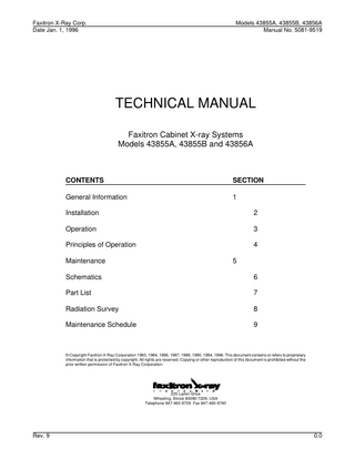
4 3 8 5 5 A Fa x i t r on Si ngl e Ca bi ne t X- Ra y Sy s t e ms ; 6 4 c m ma x i mum f oc a l di s t a nc e 10 110 kV output voltage; 3 mA continuous current, beryllium window (0.76 mm) X-ray tube; lead-shielded single cabinet; safety interlocks; 117 V, 60 Hz operation. 4 3 8 5 5 B Fa x i t r on Dua l Ca bi ne t X- Ra y Sy s t e ms ; 1 2 5 c m ma x i mum f oc a l di s t a nc e 10 - 110 kV output voltage; 3 mA continuous current, beryllium window (0.76 mm) X-ray tube; lead-shielded single cabinet; safety interlocks; 117 V, 60 Hz operation
4 3 8 5 6 A Fa x i t r on Ca bi ne t / Ta bl e X- Ra y Sy s t e ms ; 9 1 c m ma x i mum f oc a l di s t a nc e 10 - 110 kV output voltage; 3 mA continuous current, beryllium window (0.76 mm) X-ray tube; lead-shielded single cabinet; safety interlocks; 117 V, 60 Hz operation
43855A
43855B
43856A
Fig. 1.1 The Models Covered in this Manual OPTI ONS
Rev. 9
A0 2
Aut oma t i c e x pos ur e c ont r ol a nd be a m l oc a t or . Regulates exposures based on absorbed dose rather than time. Film densities can be repeatably achieved through the use of the ACE sensor which is placed under the film cassette or envelope. Compatible with A04 and standard X-ray sources.
A0 2 M
Aut oma t i c e x pos ur e c ont r ol a nd be a m l oc a t or . Used with M110 microfocus X-ray source.
A0 3
I s ol a t i on Li ne Ada pt i ng Tr a ns f or me r . This transformer has taps for 100, 190, 210, 230 and 250 V, 50 or 60 Hz. It is used to connect any of the Faxitron X-ray Systems to line voltages other than the standard 117 V, 60 Hz.
A0 4
1 0 - 1 3 0 k Vp X- r a y s our c e ; 3 mA tube current; beryllium window tube with 0.5 mm focal spot size. Recommended for thicker and/or denser samples.
M5 5
Mi c r of oc us X- r a y t ube wi t h 0 . 0 5 mm f oc a l window; 55 kVp max.
s pot
s i z e ; 0.3 mA tube current; beryllium
M1 1 0
Mi c r of oc us X- r a y t ube wi t h 0 . 0 7 mm f oc a l window; 110 kVp max.
s pot
s i z e ; 0.3 mA tube current; beryllium
A1 5
Fl uor os c opi c v i e wi ng s c r e e n; Incorporates a fluorescent screen and mirror assembly into the cabinet allowing operators an immediate view inside their samples without processing film. Primarily used for detecting the presence or absence of internal features when a permanent image is not needed.
1.2
Faxitron X-Ray Corp. Date Jan. 1, 1996
1. 5
Models 43855A, 43855B, 43856A Manual No. 5081-9519
SPECI FI CATI ONS.
RADI ATI ON SAFETY Radiation shielded cabinet. Compartment door equipped with dual safety interlocks - each compartment door and drawer on dual cabinet and table systems. Radiation: Less than 0.5 mR/hr at 5 cm (2 in.) from exterior surface at maximum kV. Certified to comply with standards set by the US Food and Drug Administration, Center for Devices and Radiological Health, (21 CFR-1020.40). Classified by Underwriters Laboratory in the US and Canada.
X- RAY TUBE
Focal spot size kV mA Beryllium window thickness X-ray beam divergence
BEAM COVERAGE ( BC) Mode l Max. BC cm SID cm Shelf Position 1 Shelf Position 2 Shelf Position 3 Bottom Shelf Position 4 Shelf Position 5 Shelf Position 6 Bottom Note:
a. b. c.
St a nda r d 0.5 mm 10-110 3 0.76 mm 30 deg.
Opt i on A0 4 0.5 mm 10-130 3 0.76 mm 30 deg.
Opt i on M1 1 0 0.07 mm 10-110 0.3 0.76 mm 30 deg.
Opt i on M5 5 0.05 mm 10-55 0.3 0.76 mm 30 deg.
AND SOURCE TO I MAGE DI STANCE ( SI D) 43855A 21 x 26 32 46 56 61 max
43855B 39 x 45 32 46 56 61 93 107 117 122 max
43856A 30 x 36 32 46 56 61
91 max
Radiation intensity exhibits normal “heel” effect, typical charts available upon request. When using options A02 or A02M, the maximum SID is reduced by about 4 cm. If unit is equipped with extension collar, add 15 cm to SID. Max BC will also increase.
EXPOSURE CONTROL Standard:
Manual timer with crystal controlled clock. 5 sec to 60 minutes (one second increments).
Option A02:
Automatic and manual.
EXTERI OR DI MENSI ONS (Approximate) Mode l 43855A 43855B 43856A Height mm (in.) * 889 (35) 1473 (58) 1803 (71) Width mm (in.) 559 (22) 559 (22) 1727 (68) Depth mm (in) 508 (20) 508 (20) 1143 (48) * If the unit is equipped with an extension collar, add 153 mm (6 in.)
Rev. 9
1.3
Faxitron X-Ray Corp. Date Jan. 1, 1996
Rev. 9
Models 43855A, 43855B, 43856A Manual No. 5081-9519
1.4
Faxitron X-Ray Corp. Date Jan. 1, 1996
Models 43855A, 43855B, 43856A Manual No. 5081-9519
SPECI FI CATI ONS (cont’d) COMPARMENT I NTERI OR DI MENSI ONS (Approximate) Mode l Height mm (in.) Width mm (in.) Depth mm (in)
43855A 368 (14.5) 457 (18) 394 (15.5)
43855B 889 (35) 457 (18) 394 (15.5)
43856A 152 (6) 1143 (45) 1143 (45)
43855B 347 (765) 386 (851)
43856A 726 (1600) 771 (1700)
WEI GHT (Approximate) Mode l Net kg (lbs) Shipping kg (lbs)
43855A 200 (440) 227 (500)
POWER REQUI REMENTS
Rev. 9
Standard:
117 VAC ±10%, 60 Hz, 600 VA.
Option A03:
Input taps for 100, 190, 210, 230 or 250 VAC ±6%, 50/60 Hz, 600 VA.
1.5
Faxitron X-Ray Corp. Date Jan. 1, 1996
1. 6
Models 43855A, 43855B, 43856A Manual No. 5081-9519
RADI ATI ON TABLES
MATERIAL
DOSE-R
Silicon semiconductor*
7 x 10⁶
Germanium semiconductor*
5 x 10⁴
Capacitor
3-7 x 10⁸
Resistor
2-5 x 10⁸
Plastics
2 x 10⁴
Ceramic, glass, optical
2 x 10⁴
Explosives
1 x 10⁸
Elastomeric materials
1 x 10⁵
* Packages normally filter at least some of the radiation from reaching the chip.
Table 1.1 Radiation Damage Thresholds (For Reference)
TUBE VOLTAGE kVp
DISTANCE FROM ANODE (CM.)
110
30.5
300
NONE
Victoreen 70/121 †
110
30.5
610
NONE
Victoreen 70/561 ††
110
63.5
70
NONE
Victoreen 70/131
110
*
51,000
NONE
Victoreen 70/651
130
30.5
400
NONE
Victoreen 70/131
130
30.5
10
0.36 Cu
Victoreen 70/131
APPROXIMATE DOSE R/MINUTE
FILTRATION (mm)
MEASURING INSTRUMENT
* At Window † Response to 30 kev †† Response to 6 kev
Table 1.2 Typical Radiation Output
Rev. 9
1.6
Faxitron X-Ray Corp. Date Jan. 1, 1996
Models 43855A, 43855B, 43856A Manual No. 5081-9519
Figure 1-2. Outline Drawing of Faxitron Standard X-ray Tube.
Rev. 9
1.7
Faxitron X-Ray Corp. Date Jan. 1, 1996
Models 43855A, 43855B, 43856A Manual No. 5081-9519
Figure 1-3. Location of Decals and Labels.
Rev. 9
1.8
Faxitron X-Ray Corp. Date Jan. 1, 1996
Models 43855A, 43855B, 43856A Manual No. 5081-9519
REGULATOR ADJ USTED AT 1 1 8 VAC PER I NSTRUCTI ON MANUAL
--
_____
*Note:
LI NE VOLTAGE OF 1 0 5 TO 1 3 0 VOLTS* Standard and Option A04 X-ray Tube Options M55 and M110 Microfocus X-ray Tube, Tube Current = mA x 0.1
While the tube Current Regulation will conform to the curve shown above over the power line voltage range of 105 to 130 volts, the tube kVp will not reach rated maximum below 118 volts.
Figure 1-4. X-ray Tube Current Regulation Characteristics.
Rev. 9
1.9
Faxitron X-Ray Corp. Date Jan. 1, 1996
Rev. 9
Models 43855A, 43855B, 43856A Manual No. 5081-9519
1.10
Faxitron X-Ray Corp. Date Jan. 1, 1996
Models 43855A, 43855B, 43856A Manual No. 5081-9519
SECTION 2 INSTALLATION
CONTENTS
Rev. 9
PAGE
2.1
Introduction ... 2.1
2.2
Initial Inspection ... 2.1
2.3
Preparation ... 2.1
2.4
Installation of Single Cabinet System 43855A ... 2.1
2.5
Installation of Dual Cabinet System 43855B... 2.2
2.6
Installation of Table System 43856A ... 2.3
2.7
Installation of Fluoroscopy Option A15 ... 2.5
2.8
Three Conductor AC Power Cable ... 2.6
2.9
Improperly Wired AC Outlets ... 2.6
2.10
Power Requirements ... 2.6
2.11
Operational Checkout and Radiation Survey ... 2.6
2.12
Claims ... 2.8
2.0
Faxitron X-Ray Corp. Date Jan. 1, 1996
Models 43855A, 43855B, 43856A Manual No. 5081-9519
SECTION 2 INSTALLATION 2.1
INTRODUCTION. This section contains information and instructions necessary for installing Faxitron Models Cabinet X-ray Systems. Included are initial inspection procedures, power and grounding requirements, environmental information, installation procedures and instructions for repackaging for shipment.
2.2
INITIAL INSPECTION. Each Faxitron system is carefully inspected both mechanically and electrically before shipment. It should be free from scratches and in perfect operating order upon receipt. To confirm this, the system should be inspected for physical damage incurred in transit. If damage is found, refer to the claims paragraph in this section. Retain the packing material for possible future use.
2.3
PREPARATION. All three systems are heavy and must be handled with care to prevent injury to personnel and/or damage to the equipment. The single cabinet system has a shipping weight of 227 kg (500 lbs), the dual cabinet system is 386 kg (851 lbs) and the table system is 771 kg (1700 lbs). For the dual cabinet system, which is top heavy, see special warning below. WARNING Read the Safety Summary at the front of this manual before installing or operating the system. NOTE. In the Continental United States, Hawaii, Alaska, Canada and certain European Countries, you can get assistance with installation from an FXC field engineer by contacting the nearest Faxitron X-Ray Corporation Sales/Service Office. The field engineer will also perform or arrange for a radiation safety survey, and he will assist in training customer personnel in proper operation and use of the system.
2.4
Rev. 9
INSTALLATION OF SINGLE CABINET SYSTEM 43855A. 1.
Remove the top and side panels of the crate.
2.
Unbolt the system from the shipping pallet.
3.
Carefully remove the sheet metal top then the metal side panels from the cabinet. Each panel can be removed by loosening the screws at the top rear of each panel and then sliding the panel back to free it from the retaining lip at the front of the cabinet. The unit (200 kg or 440 lbs) can now be removed from the shipping pallet by one of the following techniques. a.
If a hoist is available, a sling going UNDER the cabinet, should be used to lift the unit off the shipping pallet.
b.
If a hoist is not available, four or five people can lift the system. Again, lifting should be done ONLY from the frame of the cabinet.
2.1
Faxitron X-Ray Corp. Date Jan. 1, 1996
Models 43855A, 43855B, 43856A Manual No. 5081-9519
Installation of Single Cabinet System 43855A (cont'd)
2.5
4.
When the system is unloaded from the shipping pallet, it can be moved with a refrigerator type moving cart, available from U-Haul, retail dealers or an appliance store. The side of the cabinet should rest against the cart frame and a strap should be used to hold the system to the cart. The strap should be placed around the frame and above the door. DO NOT place the strap over the door as this could mechanically warp the door mounting hinges. With the system secured to the cart, carefully move it to the area where it will be installed.
5.
Using one of the procedures outlined in 3a or 3b, place the system on a sturdy, leveled table or bench. In areas where earth quake regulations are in effect, follow federal and local regulations to secure the system.
INSTALLATION OF DUAL CABINET SYSTEM 43855B.
WARNING Model 43855B is top-heavy. For safety of operating and service personnel, the system must 1. Remove topplease and side panels of the crate.of the system uncrated is 347 kg (765 be bolted to the floor. the Also note that the weight lbs). 2. Unbolt the system from the shipping pallet. 3.
Rev. 9
Carefully remove the sheet metal top and then the metal side panels from both cabinets. Each panel can be removed by loosening the screws at the top rear of each panel and then sliding the panel back to free it from the retaining lip at the front of the cabinet. The unit (347 kg or 765 lbs) can now be removed from the shipping pallet by one of the following techniques. a.
If a hoist is available, a sling going UNDER the lower cabinet, should be used to lift the unit off the shipping pallet.
b.
If a hoist is not available, six or seven people can lift the system, using one or two of the people to steady the system since it is top-heavy. Again, lifting should be done ONLY from the frame of the lower cabinet.
4.
When the system is unloaded from the shipping pallet, it can be moved with a refrigerator type moving cart, available from U-Haul, retail dealers or an appliance store. The side of the cabinet should rest against the cart frame and a strap should be used to hold the system to the cart. The strap should be placed around the frame between the doors of the two cabinets. DO NOT place the strap over the door as this could mechanically warp the door mounting hinges. With the system secured to the cart, carefully move it to the area where it will be installed.
5.
Place the system on the floor where it is to be used. By turning the adjustable feet, make certain that it is leveled and stable on the floor. Two holes with a 3/16"-16 thread are available, located inside the bottom base frame, one on each side of the unit. Depending on the floor construction and the local requirements, choose a method of securing the unit to the floor which will satisfy the requirements. For older systems with an extension base, access to bolt-down holes is gained by removing the base front cover. In areas where earth quake regulations are in effect, follow federal and local regulations to secure the system.
2.2
Faxitron X-Ray Corp. Date Jan. 1, 1996
2.6
Models 43855A, 43855B, 43856A Manual No. 5081-9519
INSTALLATION OF TABLE SYSTEM WITH PULL-OUT DRAWER RADIATION CHAMBERS, MODEL 43856A.
The system is packed in two crates. The larger of the two crates contains the table, the smaller crate the cabinet. If possible, with a forklift, move the system while still in crates, as close as possible to where they are to be installed.
Rev. 9
1.
Remove the top and side panels of the large crate for the table.
2.
The table can be lifted from the shipping pallet by using a hoist or eight strong people. The weight of the table is approximately 526 kg (1160 lbs). The table is normally not fastened to the shipping pallet.
3.
Position the table where it is intended to be located. Avail it by adjusting the four leveling screws.
4.
Remove the top and side panels of the crate for the cabinet.
5.
Unbolt the unit from the shipping pallet.
6.
Remove the four adjustable feet (one at each corner) from the bottom of the cabinet. The feet are threaded into the bottom frame.
7.
Carefully remove the sheet metal top and then the metal side panels from the cabinet. Each panel can be removed by loosening the screws at the top rear of each panel and then sliding the panel back to free it from the retaining lip at the front of the cabinet. The unit (200 kg or 440 lbs) can now be removed from the shipping pallet by one of the following techniques. a.
If a hoist is available, a sling going UNDER the cabinet, should be used to lift the unit off the shipping pallet.
b.
If a hoist is not available, four or five people can lift the system. Again, lifting should be done ONLY from the frame of the cabinet.
8.
When the cabinet unit is unloaded from the shipping pallet, it can be moved with a refrigerator type moving cart, available from U-Haul, retail dealers or an appliance store. The side of the cabinet should rest against the cart frame and a strap should be used to hold the system to the cart. The strap should be placed around the frame and above the door. DO NOT place the strap over the door as this could mechanically warp the door mounting hinges. With the system secured to the cart, carefully move it to the area where it will be installed.
9.
Using one of the procedures outlined in 7a or 7b, place the system on the already prepared steel table and align the two mounting holes with those on the table.
2.3