Huntleigh Healthcare
MP1 & MP1R Service Manual
Service Manual
28 Pages
Preview
Page 1
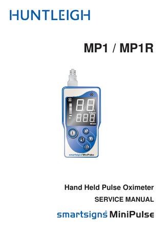
MP1 / MP1R
Hand Held Pulse Oximeter SERVICE MANUAL
This Service Manual is designed for use with the Held Pulse Oximeter.
Hand
Model Nos.: MP1 / MP1R
Although every care has been taken to ensure that the information in this manual is accurate, continuous development may result in equipment changes. The Company reserves the right to make such changes without prior notification, and resulting manual innaccuracies may occur. This manual and any changes protected by copyright.
© Huntleigh Healthcare Ltd All rights reserved
The Smartsigns® Minipulse is in conformity with the Medical Devices Directive 93/42/EEC as amended by 2007/47/EC and has been subject to the conformity assurance procedures laid down by the Council Directive
Manufactured in the UK by Huntleigh Healthcare Ltd. As part of the ongoing development programme the company reserves the right to modify specifications and materials without notice. Smartsigns® and Huntleigh are registered trademarks of Huntleigh Technology Ltd. 2007. © Huntleigh Healthcare Ltd. 2007, 2012
1. General Information ... 5 1.1 Introduction ... 5 1.2 Servicing Policy ... 5 1.3 CE Marking ... 5 1.4 Electrostatic Discharge (ESD) Precautions ... 5 1.4.1 What Is Static Electricity? ... 5
Table of Contents
Table of Contents
1.4.2 Protective Measures ... 6
1.5 Description... 6 1.6 Construction ... 7
2. Quality, Reliability and Safety ... 8 2.1 Safety ... 8 2.2 Maintenance ... 8 2.3 Cautions ... 8 2.4 General Care ... 9 2.5 Cleaning ... 9
3. Specifications... 10 3.1 Safety ... 10 3.2 Power Supply ... 10 3.3 Enclosure... 10 3.4 Auto Shut Off ... 10 3.5 Auto Dim ... 10 3.6 Controls and Indicators... 11 3.6.1 Front View ... 11 3.6.2 Rear View ... 12 3.6.3 Desk Stand / Charger ... 12
4. Technical Description ... 13 4.1 Oximetry Principle ... 13 4.2 SpO2 ... 13 4.3 Pulse Rate Meter ... 13 4.4 Bar Graph ... 13 4.5 Engineering Mode ... 14 4.6 Intelligent Auto Shut Off ... 14 4.7 Auto Dim ... 14 4.8 Calibration ... 14 3
Table of Contents
4.9 Block Diagram ... 15 4.10 Power Supply ... 15 4.11 Microcontroller ... 16 4.12 Display Driver ... 16 4.13 Audio Power Amplifier ... 16
5. Servicing Procedure ... 17 5.1 Dismantling Procedure ... 17 5.2 Main PCB Removal ... 18 5.3 Changing Components ... 19 5.4 SpO2 Module Removal ... 19 5.5 Battery Contact Replacement... 20 5.6 Contact PCB ... 21 5.7 Re-assembly... 21
6. MP1R Desk Charger... 22 6.1 Desk Charger Dismantling... 22 6.2 Charger Board Removal ... 22 6.3 Changing Components ... 22 6.4 Desk Charger Re-assembly ... 22 6.5 Mains adapter ... 22
7. Functional Test ... 23 7.1 MP1/MP1R Functional Test ... 23 7.2 Desk Charger Functional Test ... 24 7.3 Mains Adapter Functional Test ... 24
8. Fault Finding ... 25 9. Spare Parts List... 26 10.Ordering Information... 27 11.Service Returns ... 27
4
Although every care has been taken to ensure that the information in this manual is accurate, continuous development may result in equipment changes. The company reserves the right to make such changes without prior notification, and resulting manual inaccuracies may occur. This manual and any changes are protected by copyright.
1.1 Introduction This service manual provides the technical information required for the repair and and desktop charger. maintenance of the Huntleigh Healthcare Ltd
General Information
1. General Information
1.2 Servicing Policy Due to the nature of static sensitive surface mount technology, specialised equipment and training is required when working on the surface mount components used within these products. For this reason circuit diagrams are not included in this manual. Block diagrams and fault finding sections are included to make fault finding to modular or leaded component level possible. Units within the warranty period MUST NOT be dismantled and should be returned to Huntleigh Healthcare Ltd for repair. Any units returned showing signs of tampering or accidental damage will not be covered under warranty (refer to user manual for further details).
1.3 CE Marking This equipment carries a CE mark but this is only fully valid if it is used in conjunction with cables and other accessories approved by Huntleigh Healthcare Ltd.
1.4 Electrostatic Discharge (ESD) Precautions Due to the nature of the of the components used within the MP1/MP1R and the desk charger units, special precautions must be taken to avoid damage to the CMOS and microcontroller based circuitry. Static damage may not be immediately evident but could cause permanent failure.
1.4.1 What Is Static Electricity? Static electricity is generated when two materials move against one another. The voltage generated depends on the materials generating the electricity, the speed of movement, humidity and rate of discharge. All man made materials generate static, such as plastic coffee cups, plastic bags, binders and folders, all of which are likely to be within the working area. Activity
10-20% Relative Humidity
Walking across carpet
35,000 Volts
Walking across vinyl floor
12,000 Volts
Working at bench
6,000 Volts 5
General Information
Activity
10-20% Relative Humidity
Plastic folder
7,000 Volts
Poly bag lifted from bench
20,000 Volts
Foam padded work chair
18,000 Volts
Static electricity is generated very easily, and is only felt by us when we discharge the built up charge rapidly by touching a grounded object such as a door handle. The voltages felt by us are as low as 3kV, but only 20V is necessary to damage some components. Voltages as high as 35kV and current spikes of 40A have been known. The damage to the component or assembly can be immediate or latent. Latent damage is not immediately obvious but can lead to the circuitry subsequently failing or becoming erratic.
1.4.2 Protective Measures Measures must be taken to ensure that all charges generated are safely discharged before they build up to a dangerous level. The use of dissipative mats for the work surface and wearing anti-static wrist straps are recommended ways of preventing this problem. The dissipative mats must be connected to ground via a resistance and the wrist strap to the same ground point. Anti-static bags must be used when storing or transporting static sensitive components. Conductive mats are no longer regarded as being suitable, as a PCB or component could be electrostatically charged and it would be rapidly discharged be placing it on the conductive mat. This sudden discharge would be as damaging as placing a charged object in contact with the PCB or device. All static sensitive devices or assemblies must be placed within an anti-static bag or container whenever being moved away from the specialised handling area.
1.5 Description The MP1 range is designed for portable handheld spot monitoring of blood oxygen saturation levels by means of Photoplethysmographic sensor. MP1 is a hand held pulse oximeter MP1R is a hand held pulse oximeter and is fitted with rechargeable batteries. It is compatible with the supplied desk charger stand and mains adapter. The desk top charger allows charging of the MP1R with rechargeable batteries fitted only, with visual indication of the charge status by means of a tricolour LED. DO NOT FIT STANDARD ALKALINE BATTERIES TO THE MP1R For further information on the MP1 and MP1R, please refer to the user manual. 6
The MP1 is comprised of a main board, SPO2 module, case assembly and membrane keypad. The MP1R has an additional contact PCB assembly for charger input. The main board is powered by 4 AA cells and provides a regulated power supply for the on-board electronics and ‘piggy back’ SpO2 module. At the heart of the main board is a microcontroller that receives data from the SPO2 module and displays this to the user on 7 segment displays. It also outputs an audio signal to indicate either an alarm condition or audible beep in time with the patients heart beat. User input via the membrane keypad is also processed by the microcontroller. The board is populated with components on both sides, the majority of which are surface mount devices. If failure of such devices is suspected then the unit should be returned to the Huntleigh Healthcare service department for repair. Conventional through-hole components that may be replaced are the 7 segment displays and single LED (LED 1 to LED 7) and the 9 way ‘D’ type connector CON1. The SpO2 module, although nonserviceable, can be substituted with a replacement if deemed faulty.
General Information
1.6 Construction
The case is moulded in flame retardant ABS with a rubber outer surround for protection. The case comprises of 9 individual parts and they are as follows:
Front Case Rear Case Battery Cover without lock or Battery Cover with lock MP1R Battery cover locking tab Belt clip Finger Sensor Surround Display Bezel Membrane switch overlay
The MP1R Is supplied with a desk top charger that comprises of a mains adapter and desktop charger stand. The mains adapter is an OEM supplied part that must be returned to Huntleigh Healthcare with its desktop charger if suspected. The desktop charger comprises of three parts:
top casing bottom casing charger PCB assembly.
The charger PCB assembly is constructed of surface mount devices with only two conventional devices fitted to the assembly and they are the DC input socket and the tricolour LED. For service, return to Huntleigh Healthcare fitted in its original unit.
7
Quality, Reliability and Safety
2. Quality, Reliability and Safety 2.1 Safety The MP1 and MP1R are manufactured to high standards of performance, reliability and safety. In the event that the unit should require any repair or dismantling, the unit should be fully inspected and a full functional test carried out upon completion.
2.2 Maintenance Regular inspections must be made to check the integrity of the MP1/R and its related finger sensors, mains adapters and desktop chargers (where applicable). Ensure that no cables are showing signs of wear or become intermittent when flexed. For functional testing refer to section 8 of this manual. If you require any further assistance with the safety testing of your MP1, MP1R or your desktop charger and mains adapter, contact Huntleigh Healthcare Ltd or your supplier directly. For the U.K. refer to the Health Equipment Information Document Number MHRA DB2006 (05) – Managing Medical Devices. The following safety summary should be read before operating or carrying out any of the procedures described in this manual.
2.3 Cautions Do not use the MP1, MP1R or desk top charger and mains adapter in the presence of flammable gases such as anaesthetic agents. This product is not designed for sterile use. Do not use in the sterile field unless additional barrier precautions are taken. Do Not
8
immerse in any liquid, including probe. use solvent cleaners use high temperature sterilising processes (such as autoclaving) use E-beam or gamma radiation sterilisation.
Care
Maintenance
Storage
The main body of the MP1/R is robust and coated with a protective jacket of rubber to protect from accidental knocks and falls. Care should be taken not to crush or damage the sensor, sensor cable or connector. Other than routine cleaning and the replacement of batteries the MP1, MP1R, desktop charger and mains adapter are maintenance free. If you intend to store your MP1/R for a long period of time, the batteries should be removed.
2.5 Cleaning Caution
Quality, Reliability and Safety
2.4 General Care
Phenolic, or antiseptic solution such as steriscol or hibiscrub should never be used on any part of the system, as these chemicals will damage the case materials.
Care of the Sensor Clean the probe after each use. Clean the surface to the sensor and cable with a soft gauze pad by saturating it with a solution of 70% isopropyl alcohol. If low level disinfection is required, use a 1:10 bleach solution.
Care of the Unit If cleaning is required, wipe the Pulse Oximeter’s surfaces with a soft cloth moistened with a non-abrasive cleaner. Do not allow any liquid to enter any part of the system
9
Specifications
3. Specifications 3.1 Safety Type of protection against electric shock
Class 2 internally powered
Degree of protection against electric shock
Type BF
Mode of operation
Continuous
Degree of protection against water ingress
IPX1
Degree of safety in the presence of flammable gases
Not suitable for use in the presence of flammable gases
3.2 Power Supply MP1/R Battery Type
4 off nickel metal hydride NH15- AA 2500mAH or equivalent
MP1 Battery Type
Alkaline LR6 or equivalent
Mains Adapter Wall Cube Type
Input Voltage 100-240 VAC Output 9V For use with MP1/R desk charger only
@ 6VA
3.3 Enclosure MP1, MP1/R Case Material
Injection moulded ABS/PC with fixed rubber protective outer
Dimensions (Height x Width x Depth)
140 x 77 x 26
Weight
323gms ( including probe and batteries)
3.4 Auto Shut Off MP1 and MP1/R
If no probe or no finger is detected for 3 minutes, this function can be disabled in settings (Default is Enabled)
3.5 Auto Dim MP1 and MP1/R 10
The unit will auto dim after 2 minutes. This function can be disabled in settings.
3.6.1 Front View Item 1
Description Sensor connection 1
2
Loudspeaker
3
Protective grip
4
Display
5
Front Panel
6
Keypad
Specifications
3.6 Controls and Indicators
2
3 4
5
6
Display 2 x large 7 segment L.E.D. Display 3 x small 7 segment L.E.D. Display
2 x large segments display SpO2 3 x small segments display Heart Rate
Bar graph
Displays Perfusion Index and pulse indication
Keypad Button
Description
Button
Description
Power - ON / OFF Key
Up Key
MENU – Alarm limits and Pulse tone setting
Down Key
Alarm suspend - turns the alarms ON or OFF. Press and hold for 2 seconds to permanently disable the alarms; the system will sound a confirmation tone.
11
Specifications
3.6.2 Rear View 1 Item
Description
1
Probe socket
2
Probe storage
3
Belt Clip
4
Rear Panel
5
Battery Cover
6
Contacts
2 3
4
5
Rear panel Symbol Description Attention, consult accompanying documents / Instructions for Use.
6
Type BF applied part
Battery Cover (MP1R) 2
1
2. Remove battery cover.
1. Remove fixing screw.
3.6.3 Desk Stand / Charger
MP1 12
MP1R
4.1 Oximetry Principle Oximetry is the method of non-invasively measuring the percentage haemoglobin saturation in oxygen. The SpO2 percentage is directly correlated to the partial pressure of oxygen in haemoglobin; this determines how well oxygen is being delivered to the bodies’ cell tissue. The measurement is determined by transmitting two known wavelengths of light, one red (660nm, 2.0mW) and one infrared (905nm, 2.0-2.4mW), through a blood sample. The light is absorbed by haemoglobin at specific amounts depending on the levels of oxygenated haemoglobin and de-oxygenated haemoglobin. By measuring the light levels, by means of a photo detector, the resulting signal strengths are measured and processed. From this, the SpO2 can be determined.
Technical Description
4. Technical Description
4.2 SpO2 The MP1 range uses an OEM module to determine %SpO2. By separating the time variant parameters of SpO2 and arterial volume from the invariant parameters of tissue thickness, skin colour, light intensity, and venous blood, SpO2 can be calculated from the results, where oxygenated blood absorbs less red-light, and passes more infrared light than deoxygenated blood at a predictable amount. The SpO2 measurement from the module is processed and monitored by the on board micro processor for alarm limits and interfaced to the display circuitry and audio circuitry. The determined SpO2 rate is displayed on the 2 large 7 segment displays.
4.3 Pulse Rate Meter Each time the heart contracts, there is a surge of arterial blood, which momentarily increases arterial blood volume across the measuring site. During these surges the light absorption is increased. By monitoring these surges in light absorption, the pulse rate can be determined. The pulse rate is determined by the SpO2 module. This is further processed for upper and lower alarm limits and interfaced to the display and audio circuitry by the on board micro processor. The determined pulse rate is displayed on the 3 small 7 segment displays.
4.4 Bar Graph The bar graph displays the pulsatile signal or perfusion index. To obtain the perfusion index, press and hold the up arrow key while taking an SpO2 measurement. A Real time plethysmogram waveform is converted and displayed in bar graph form.
13
Technical Description
4.5 Engineering Mode Press and hold the menu key while switching the unit on. The screen will immediately illuminate displaying the version number of the software programmed into the on board micro processor. Each press will scroll you through the different engineering mode settings and tests.
On holding menu key
This displays the software revision number of the installed software for the MP1/R Micro processor.
1st Press of the menu key Current auto off setting (DEFAULT IS ON) 2nd Press
Current auto dim setting (DEFAULT IS ON)
3rd Press
Full display illumination test
4th press
Scroll through display count and audio test
5th press
Back to the software revision screen
If at any time the default upper and lower alarm limits and power saving functions need to be restored while the unit is in engineering mode and displaying the software revision, press and hold the alarm mute key until the MP1/R emits a short tone. This indicates that the factory defaults for all alarm limits and power saving functions have been restored.
4.6 Intelligent Auto Shut Off The software contains some power saving features to prolong the run time of the MP1/R on a single charge or a single set of non re chargeable batteries. One of these features is the auto function that monitors the unit’s activity. If there is no alarm condition, no finger or no probe, the unit will automatically switch off after 3 minutes. If the no finger alarm is triggered, the unit will not switch off unless the alarm has been suspended. With the MP1/R in Engineering mode and displaying the software version number, (refer to 4.4), press the menu key once. The display will show “Ao on” or “Ao off” ,(default is on), using the up or down arrow keys to toggle between on and off.
4.7 Auto Dim Another power saving feature of the MP1/R is the auto dim function. The display will automatically dim to 50% brightness after 2 minutes. This reduces the current required by the display and increases battery life by more than 50%. With the MP1/R in Engineering mode and displaying the software version number, (refer to 4.5), press the menu key twice. The display will show “Ad on” or “Ad off” (default is on) using the up or down arrow keys to toggle between on and off.
4.8 Calibration The MP1/R does not require user calibration, the SpO2 is calibrated at manufacture and requires no additional routine calibration. Regular performance checks can be performed with an SpO2 patient simulator.
14
Keypad
Display Driver
Microcontroller
Batteries
Audio Amplifier
SpO2 Module
Finger Probe
Technical Description
4.9 Block Diagram
Power Supply and low battery detection
Battery charger input terminals (MP1R only)
4.10 Power Supply The power supply regulates the battery voltage using a switch mode DC-DC converter, to supply a stable 3.3V to the display drivers and displays. An additional 3.3V regulator provides a seperate continuous supply for the microcontroller and SpO2 module (switched). The audio amplifier is fed from the unregulated battery supply. When the MP1/R is in the off state, the micro controller and audio amplifier are in a state of sleep. Pressing the on/off button wakes the micro processor, which in turn wakes the audio amplifier and the DC-DC converter for the SpO2 module and display driver. The unit will remain in the ‘ON’ state until:1. 2. 3. 4.
The auto shut down time has elapsed (no activity for 3 minutes) The low battery detection has switched the unit off The unit has been switched off using the key pad The MP1R has been placed on its desktop charger
15
Technical Description
4.11 Microcontroller The micro controller contains software that monitors the SpO2 and heart rate and ensures that they are within the user defined, upper and lower limits. It also interfaces the SpO2 module and displays the SpO2 readings and resultant heart rate. A pulse beep indicator is sent from the SpO2 module to the micro controller. The controller uses this indicator to light the pulse indicator led and to emit the pulse tone. A Real time plethysmogram waveform is received from the SpO2 module which is converted in software to a bar graph format then displayed on the bar graph. The micro controller also controls all the functions of the key pad, low battery detection and low battery shut down.
4.12 Display Driver The MP1/R display is driven by a serial interfaced eight digit common cathode display driver. It drives eight digits, each digit comprising of eight LED’s, although only six of these digit drivers are used. The display driver is serial interface to the micro controller. This interface is used to write configuration settings, such as display brightness and blink rate, and display data.
4.13 Audio Power Amplifier Audio tones are generated by the micro controller, in relation to the data received from the SpO2 module. These tones are amplified by the audio power amplifier then out putted to the audio speaker.
16
5.1 Dismantling Procedure 1.
Remove the battery cover by pressing in the locking tab and lifting the cover away. The MP1R is fitted with a screw lock that will need to be unscrewed before the cover can be removed.
2. 3.
Remove the 4 AA batteries. Remove the rear cover retaining screw located below the product label. DO NOT ATTEMPT TO PRISE THE CASE COVER APART. This will cause permanent damage and the case will need to be replaced. Pressing in the sides of the back cover will release the side clips and allow you to lift the rear cover away.
4.
Servicing Procedure
5. Servicing Procedure
17
Servicing Procedure
5.2 Main PCB Removal Remove the rear cover as described in section 5.1
1. 2.
Unplug the keypad ribbon cable from CON2. De-solder the battery terminal connections. Note the red battery wire must go to TP8 on the main electronics assembly and the red wire from the charge terminal must go to TP5. SIDE B TP7 TP6 CON4 CON1
TP8
18
CON3
CON2
TP5
3.
When lifting the main electronic PCB away from locating lugs on the front case assembly, remove to one side the plastic connector surround for the finger probe connector CON1.
There are no user serviceable parts on the PCB assemblies.
5.4 SpO2 Module Removal Remove the rear cover as described in section 5.1 1. The SpO2 board can be carefully unplugged from the main electronics PCB. 2. Plug in a replacement SpO2 module.
Servicing Procedure
5.3 Changing Components
SpO2 Module
19
Servicing Procedure 20
5.5 Battery Contact Replacement Battery contacts can be removed using nose pliers. 1.
Desolder battery contact wires where applicable.
2.
Ensure that there is no surplus solder on the battery contacts during reassembly.