INVOS
Medtronic Electrosurgical Generators
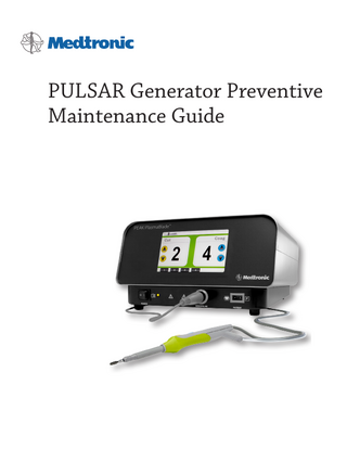
PULSAR Generator Preventative Maintenance Guide Rev C Feb 2014
Preventative Maintenance Guide
6 Pages
Preview
Page 1
PULSAR Generator Preventive Maintenance Guide
Intended Use of this Document WARNING: The information contained in this document is intended for the use of qualified personnel only. Biomedical technicians (e.g., ICC Certified Biomedical Equipment Technician [BMET]) or similar personnel performing the steps outlined here shall be fully familiar with all documentation on the functions, operations, warnings and components of the PULSAR/ PULSAR ll Generator. Serious injury can result if the activities described in this document are attempted by unqualified persons.
PULSAR Generator Preventive Maintenance Procedure The PULSAR (and PULSAR II) Generator provides radio frequency (RF) energy to a disposable electrosurgical device. This combined system is used to perform electrosurgery. The generator is capable of delivering multiple CUT and COAG modes at various power levels when connected to a PEAK PlasmaBlade™ disposable device. Every disposable device (PEAK PlasmaBlade) has a memory chip with ten set points for CUT modes and ten set points for COAG modes. This chip specifies the output power for each set point. The generator reads this memory chip to deliver RF power.
Equipment Required The following equipment will be required to complete the output power accuracy testing: • PULSAR or PULSAR II generator • A neutral electrode (return pad) connector with the pad cut off and the two leads shorted together. • PEAK PlasmaBlade disposable device (any one of PEAK PlasmaBlade 4.0, 3.0S, TnA, Needle, or PLUS). • Electrosurgical analyzer (ESU) (capable of measuring RF output at 1MHz and 460KHz). • Oscilloscope and current sensing coil (both with 50 MHz capability). Note: This equipment is required for cut modes 1-5 on both generator models.
Power Output Tests See Appendix on page 4 for test procedure. The Power Output Tests provide a means for the user to verify the accuracy of the RF energy output. The procedure to measure output power is as follows: 1.
Connect the PEAK PlasmaBlade device to the generator under test.
2.
Connect the tip of the PEAK PlasmaBlade device (metal needs to be exposed) to the ESU leads using an alligator clip.
3.
Connect the shorted leads of the neutral electrode to the ESU leads using an alligator clip.
4.
Set the load on the ESU to the value indicated on the appropriate table, (Table 1 for PULSAR II and Table 2 for PULSAR I). Refer to the ESU’s Instruction manual for set up instructions.
5.
Power on the generator and adjust to the appropriate set point per the table.
6.
Press the button (yellow for CUT and blue for COAG) on the PlasmaBlade device to activate RF. Measure the output power on the ESU. Refer to Tables 1 and 2 for accuracy of measured power depending on the type of device connected.
7. This should be repeated for all the values highlighted in blue italics at a minimum. Other values are presented for additional testing. 8.
Per IEC 60601-2-2: a.
2
201.12.1.101 Accuracy of output control setting For output powers in excess of 10% of the RATED OUTPUT POWER, the actual power as a function of the load resistance and output control setting shall not deviate from that shown in the diagrams specified in 201.7.9.3.1 by more than +/- 20%.
Table 1. Pulsar II Power Output Specs Setting
Mode
Power (Watts)
Impedance (Ohms)
Tolerance
Cut 1
Low Cut 1
0.5
100
*None Prescribed
Cut 2
Low Cut 1
2
100
*None Prescribed
Cut 3
Low Cut 1
6
100
+/- 20%
Cut 4
Low Cut 1
10
100
+/- 20%
Cut 5
Low Cut 1
20
100
+/- 20%
Cut 6
Medium Cut
20
400
+/- 20%
Cut 7
Medium Cut
35
400
+/- 20%
Cut 8
Medium Cut
50
400
+/- 20%
Cut 9
High Cut (Blend 1)
25
400
+/- 20%
Cut 10
High Cut (Blend 2)
50
400
+/- 20%
Coag 1
Low Coag 1
15
400
+/- 20%
Coag 2
Low Coag 1
20
400
+/- 20%
Coag 3
Low Coag 1
25
400
+/- 20%
Coag 4
Low Coag 1
30
400
+/- 20%
Coag 5
Low Coag 1
35
400
+/- 20%
Coag 6
High Coag
30
500
+/- 20%
Coag 7
High Coag
35
500
+/- 20%
Coag 8
High Coag
40
500
+/- 20%
Coag 9
High Coag
45
500
+/- 20%
Coag 10
High Coag
50
500
+/- 20%
* Max Power setting for this mode is 40W, therefore is not required to be within 20% tolerance according to IEC 60601-22 due to it being less than 10% of the max power setting.
Table 2. Pulsar I Power Output Specs Setting
Mode
Power (Watts)
Impedance (Ohms)
Tolerance
Cut 1
Low Cut 1
0.5
40
*None Prescribed
Cut 2
Low Cut 1
2
40
*None Prescribed
Cut 3
Low Cut 1
6
40
+/- 20%
Cut 4
Low Cut 1
10
40
+/- 20%
Cut 5
Low Cut 1
20
40
+/- 20%
Cut 6
Medium Cut
20
600
+/- 20%
Cut 7
Medium Cut
35
600
+/- 20%
Cut 8
Medium Cut
50
600
+/- 20%
Cut 9
High Cut (Blend 1)
25
600
+/- 20%
Cut 10
High Cut (Blend 2)
50
600
+/- 20%
Coag 1
Low Coag 1
15
600
+/- 20%
Coag 2
Low Coag 1
20
600
+/- 20%
Coag 3
Low Coag 1
25
600
+/- 20%
Coag 4
Low Coag 1
30
600
+/- 20%
Coag 5
Low Coag 1
35
600
+/- 20%
Coag 6
High Coag
30
1000
+/- 20%
Coag 7
High Coag
35
1000
+/- 20%
Coag 8
High Coag
40
1000
+/- 20%
Coag 9
High Coag
45
1000
+/- 20%
Coag 10
High Coag
50
1000
+/- 20%
* Max Power setting for this mode is 40W, therefore is not required to be within 20% tolerance according to IEC 60601-22 due to it being less than 10% of the max power setting.
3
Appendix Procedure for measuring the Pulsar Generator output power at Low Cut settings. Due to the low duty cycle characteristics of the low cut settings (Cut 1 through 5) of the Pulsar generator, it is necessary to follow these instructions to accurately measure the true rms output power for these settings.
Equipment Required: •
Pulsar Generator and PEAK PlasmaBlade hand piece
•
Oscilloscope
•
Current sensing coil (i.e.: Pearson Wide Band Current Monitor model 4100 or similar)
•
100 ohm non-reactive resistive load - Pulsar II
•
40 ohm non-reactive resistive load - Pulsar I
Test Setup:
Load (100Ω or 40Ω)
Use the test configuration above, keeping all interconnecting leads as short as possible. Set the oscilloscope x-axis time base to 1μs/division and the measurement to volts rms.
Procedure: Set the Pulsar generator to the desired setting (Cut 1 through 5) and activate the Cut (yellow) finger switch on the PEAK PlasmaBlade device. Adjust the trigger and delay on the oscilloscope to capture the rf signal with no “off” time in the screen. See the example screen to the right: Record the rms amperage indicated on the oscilloscope.
4
Calculate the resulting power (Watts) utilizing the equation and table below:
(l
2
x Duty Cycle
)
xR
I = Amps rms R = See indicated loads in Tables 1 and 2. Note: Equation into Spreadsheet example:
Table 3: Duty Cycle for Pulsar Generator (PEAK Plasmablade 4.0 & 3.0S) setting Setting
Duty Cycle
“On” Time
Repeat Cycle
Cut 1
0.0017
18 μs
40100 μs
Cut 2
0.0072
5261 μs
Cut 3
0.0144
Cut 4
0.0235
Cut 5
0.0353
38 μs 50 μs 62 μs 76 μs
3461 μs 2640 μs 2150 μs
i.e. (2.4^2 x 0.0353) x 100 = 20.33 Watts
Notes: For accuracy of output power measurement, IEC 60601-2-2 states: 201.12.1.101 Accuracy of output control setting For output powers in excess of 10% of the RATED OUTPUT POWER, the actual power as a function of the load resistance and output control setting shall not deviate from that shown in the diagrams specified in 201.7.9.3.1 by more than ± 20%.
5
70-10-1231 Rev C 2014/02 © Copyright 2013 Medtronic Advanced Energy LLC.
© 2013, Medtronic, Inc. All rights reserved. PEAK, PEAK PlasmaBlade and PULSAR are registered and/or trademarks of Medtronic, Inc. U.S. Patent Nos. 6,135,998, 6,730,075, 6,780,178, 7,238,185, 7,357,802, 7,736,361, and 7,789,879. Additional patents pending. Note: The information contained in this document was accurate at the time of publication. Medtronic reserves the right to make changes to the product described in this manual without notice and without incorporating those changes into any products already sold. No part of this document may be reproduced in any manner, or transmitted by any form or means electronic or mechanical, for any purpose without the express written permission of Medtronic Advanced Energy.
Caution: Federal Law (USA) restricts these devices to sale by or on the order of a physician. For a listing of indications, contraindications, precautions, and warnings, please refer to the Instructions For Use (IFU) that accompany PEAK PlasmaBlade™ disposable devices and/or the PULSAR/PULSAR ll Operator’s Manual.
Medtronic Advanced Energy LLC 180 International Drive Portsmouth, NH 03801 USA Tel 866.777.9400 Fax 866.222.0900
www.medtronicadvancedenergy.com manuals.medtronic.com