Technical Documentation
110 Pages
Preview
Page 1
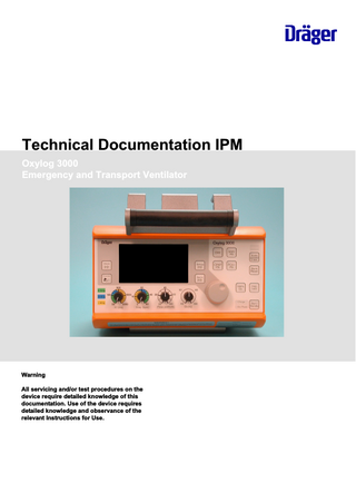
Technical Documentation IPM Oxylog 3000 Emergency and Transport Ventilator
Warning All servicing and/or test procedures on the device require detailed knowledge of this documentation. Use of the device requires detailed knowledge and observance of the relevant Instructions for Use.
No.1505_0000005861-001
This page intentionally left blank.
2
Oxylog 3000
Technical Documentation IPM
Table of contents
Table of contents 5 6 9 10 11 15 17 18 23
No.1505_0000005861-001
General 1 General notes ... Function descriptions 1 General information ... 2 Pneumatic assembly ... 3 Electronic assembly... 4 AGSS... 5 Function... Annex
Technical Documentation IPM
Oxylog 3000
3
Table of contents
No.1505_0000005861-001
This page intentionally left blank.
4
Oxylog 3000
Technical Documentation IPM
General
This chapter contains general notes and definitions that are important for the use of this documentation.
General notes ...
6
No.1505_0000005861-001
1
Technical Documentation IPM
Oxylog 3000
5
General General notes
1
General notes
1.1
Notes on use Read through the following notes thoroughly before applying this documentation. Dräger reserves the right to make changes to the device and/or to this documentation without prior notice. This documentation is intended solely as an information resource for maintenance personnel or technical specialists.
1.2
Copyright and other protected rights The content of this documentation, in particular its design, text, software, technical drawings, configurations, graphics, images, data and their selection and its composition and any amendments to it (content) are protected by copyright. The content must not (in whole or in part) be modified, copied, distributed, reproduced, republished, displayed, transmitted or sold without the prior written consent of Dräger.
1.3
Definitions WARNING An important advisory indicating a potentially hazardous situation which may result in death or serious injury if not prevented. CAUTION An important advisory indicating a potentially hazardous situation which may result in minor or moderate injury to the user or patient or in damage to the medical product or other assets if not prevented. NOTE A NOTE provides additional information intended to avoid inconvenience during operation and/or servicing. Term Maintenance
Maintaining the operative condition of a medical product by suitable means
Inspection
Assessment of the actual condition of a medical product
Servicing
Maintaining the operative condition of a medical product by recurrent, specified measures
Repair
Restoring the operative condition of a medical product after failure of a device function
General safety precautions Read through each section thoroughly before beginning servicing. Always use the correct tools and the specified test equipment. Otherwise the device may not work correctly or may be damaged.
6
Oxylog 3000
Technical Documentation IPM
No.1505_0000005861-001
1.4
Definition
General General notes
WARNING The device must be regularly inspected and serviced by maintenance personnel. Repairs and complex maintenance work on the medical product must be carried out by qualified specialists. If you require a service contract, or for any necessary repair work, Dräger recommends DrägerService. Dräger recommends using original Dräger parts for servicing. If the aforementioned instructions and recommendations are ignored, the correct functioning of the medical product may be put at risk. Pay attention to the "Servicing" section of the Instructions for Use. WARNING Non-conforming test values If test values do not conform to specifications, the safety of the patient may be put at risk. –
Do not put the device into operation if test values do not conform to specifications.
–
Contact your local service organization.
WARNING Impermissible modifications to the device If impermissible modifications are made to the device, the safety of the patient may be put at risk. Do not modify the device without Dräger's permission. WARNING Risk of infection The unit may transmit pathogens following use on the patient. –
Before carrying out any servicing, ensure that the device and its components have been handed over by the user cleaned and disinfected.
–
Service only cleaned and disinfected units and unit components.
WARNING Risk to patient. Ensure that no patient is connected to the device before starting maintenance or repair work. NOTE
No.1505_0000005861-001
Where reference is made to legislation, regulations and standards, in respect of devices used and serviced in Germany they are based on the laws of Germany. Users and technicians in other countries must comply with their national laws and/or international standards.
Technical Documentation IPM
Oxylog 3000
7
General General notes
No.1505_0000005861-001
This page intentionally left blank.
8
Oxylog 3000
Technical Documentation IPM
Function descriptions
This chapter contains descriptions of the device's technical functions.
General information ... Pneumatic assembly ... Electronic assembly... AGSS... Function...
10 11 15 17 18
No.1505_0000005861-001
1 2 3 4 5
Technical Documentation IPM
Oxylog 3000
9
Function descriptions General information
1
General information The Oxylog is a time-cycled, volume-controlled emergency and transport ventilator with pressure support for patients requiring machine or assisted ventilation. For use by and under supervision of trained health care professionals.
1.1
Functional principle The Oxylog primarily comprises the pneumatic components with the connection and metering block and the control and display electronics (Fig. 1). The connection block supplies a constant pressure to the metering block, contains the safety functions such as the emergency air and safety valves, control the pressure (PEEP) during expiration and, together with the ventilation accessories, provides the interface to the patient. The metering block passes defined volumes of gas to the connection block.
4293
The control and display electronics evaluate the measurement signals, control the valves and provide the interface to the operator.
Functional principle
No.1505_0000005861-001
Fig. 1
10
Oxylog 3000
Technical Documentation IPM
Function descriptions Pneumatic assembly
2
Pneumatic assembly
399
The description relates to the following pneumatics diagram. The Control PCB evaluates the measurement signals of the sensors and actuates the valves.
Fig. 2
Pneumatics diagram Key to Fig. 2
Item
Designation
1
Connection block
2
Metering block
No.1505_0000005861-001
DR Pressure regulator (PR) E1
Ejector
F1
Filter in O2 compressed gas connection port
F2
Filter for intake air
L1
L1 makes sure there is an even flow
NV
Emergency-air valve
S1
Flow sensor to measure internal inspiratory flow
S2
Flow sensor to measure the ambient air intake
S3
Pressure sensor (Pv) to measure supply pressure for valves V1 to V3
S4
Pressure sensor (Pint) to measure unit-internal patient pressure
S5
Pressure sensor (Paw) to measure pressure close to patient
Technical Documentation IPM
Oxylog 3000
11
Function descriptions Pneumatic assembly
Item
Designation
S6
Pressure sensor (delta P) to measure differential pressure at external flow sensor
S7 and S9
Pressure sensors to measure ambient pressure
S8
External flow sensor
SV
Safety valve
V1 to V3
Metering valves
V10
Ventilation valve
V6
PEEP valve
V7 and V8
Switching valves to calibrate pressure sensors S5 and S6
V9
Non-return valve
2.1
Inlet The compressed oxygen passes through the filter F1 and the pressure regulator DR to the valves V1 to V3. The pressure regulator regulates the pressure to 3 bar. This is done to attain a stable flow control. The Control PCB monitors this pressure, which is measured with sensor S3.
2.2
Metering unit Valves V1 to V3 are proportional valves, each delivering a flow proportional to the overall flow of 0 to 35 L/min. The flow sensor S1 measures the delivered flow and the Control PCB corrects the valve operation as necessary. Valve V3 comprises two parallel configured valves, to produce a total flow greater than 100 L/min. With the valve V1 and the ejector E1 ambient air can additionally be drawn in. Valve V1 meters a flow through the ejector. The resultant negative pressure draws ambient air through the filter F2, the flow sensor S2 and the non-return valve V9. Valve V2 adds oxygen to the ambient air depending on the selected O2 concentration.
At flows less than 9 L/min the volume of intake air is so low that an oxygen concentration of 40% is no longer guaranteed. At flows greater than 35 L/min oxygen is added accordingly. An oxygen concentration of 40% is no longer guaranteed.
12
Oxylog 3000
Technical Documentation IPM
No.1505_0000005861-001
The proportion of ambient air may be a maximum of 75%. The minimum oxygen concentration may thus be 40%.
Function descriptions Pneumatic assembly
In a flow range from 9 to 35 L/min an oxygen concentration of 40% or 100% (Oxylog 2000 plus) or 40% to 100% (Oxylog 3000) can be set. The nonreturn valve V9 prevents oxygen escaping into the ambient air. L1 prevents swirling, and ensures a uniform oxygen concentration.
2.3
Sensors and safety functions The flow sensor S1 measures the inspiratory flow inside the unit and the Control PCB corrects the operation of valves V1 to V3 as necessary based on the measured value. The safety valve SV opens at a pressure greater than 80 mbar, to prevent the patient from being exposed to high pressure in the event of unit malfunctions. The emergency breathing valve NV allows the patient to breathe spontaneously in case the unit fails. The pressure sensor S4 measures the internal patient pressure inside the unit and the PEEP pressure at the ventilation valve V10.
351
The pressure sensor S6 measures the differential pressure above the flow sensor S8 located close to the patient (Fig. 3). From it, the Control PCB calculates the flow.
Fig. 3
Functional principle of the external flow sensor
Pressure sensor S5 measures the pressure at the patient. Based on this pressure value, the Control PCB makes calculations including for actuation of the PEEP valve V6. Valves V7 and V8 switch the connections of S6, S5 against atmosphere at cyclic intervals. The Control PCB calibrates the sensors and any offset drift is prevented.
2.4
PEEP valve
No.1505_0000005861-001
The PEEP valve V6 controls the PEEP setting of the ventilation valve V10. The Control PCB actuates a coil which delivers a pressure to a diaphragm. The internal tubing system vents to this preset PEEP pressure during expiration.
Technical Documentation IPM
Oxylog 3000
13
Function descriptions Pneumatic assembly
This PEEP pressure also acts on a valve diaphragm in the ventilation valve V10 (Fig. 4/1). On expiration the preset PEEP pressure is established at the patient. During expiration an internal flow of 0.5 L/min flows through the PEEP valve V6 to hold the diaphragm of the PEEP valve still and ensure uniform opening of the PEEP valve.
349
During inspiration the PEEP valve V6 is closed by an actuation current of 130 mA.
Fig. 4
2.5
Ventilation valve
Ambient pressure conditions
No.1505_0000005861-001
The Oxylog meters the tidal volume under BTPS conditions. Sensors S7 and S9 measure the ambient pressure. S5 measures the current pressure level in the lung. In this way the Control PCB can balance fluctuating ambient pressure and the BTPS conditions (Body Temperature, Pressure, Saturated. Measurements referred to conditions of the patient's lung, body temperature 37 °C, ambient pressure, water vapor saturated gas).
14
Oxylog 3000
Technical Documentation IPM
Function descriptions Electronic assembly
3
Electronic assembly
4309
The description refers to the following block diagram, and depicts only the underlying principle. The connections of the individual modules are only indicated indirectly, and are made by cable harnesses, connectors and the conductors on the individual PCBs.
Fig. 5
Electronics block diagram
3.1
Charging Circuit PCB The Charging Circuit PCB controls charging of the internal replaceable battery and selection of the voltage supply (mains, on-board system or internal battery). The Charging Circuit PCB accommodates the input for the external voltage supply. The input is isolated from the remaining electronics by a protective circuit. The Charging Circuit PCB directly activates the power indicator LEDs. The LEDs are located on the front membrane cover. The Charging Circuit PCB has its own processor system, and thus its own software. This software is also located on the Control PCB, and is loaded from there onto the Charging Circuit PCB.
No.1505_0000005861-001
The internal replaceable battery has various dummy resistors, depending on the type used. The Charging Circuit PCB detects on the basis of the resistor which type is fitted (nickel metal hydride or lithium ion).
Technical Documentation IPM
Oxylog 3000
15
Function descriptions Electronic assembly
The temperature and charge capacity of the internal replaceable battery is determined by the battery itself. These data are transmitted from the Charging Circuit PCB to the Control PCB.
3.2
Sensor PCB The Sensor PCB holds all the pressure sensors of the pneumatic system and the internal temperature gauge. The Sensor PCB is the interface for pressure measurement and valve actuation between the pneumatic and electronic systems.
3.3
Front membrane cover On the front membrane cover are the keys, the LEDs and the rotary knob. Together with the display, the rotary knob and the potentiometers, the front membrane cover is the interface between the unit and the operator. The display is an EL display. EL stands for electroluminescent.
3.4
Control PCB The Control PCB holds the electronic ON/OFF switch components, the voltage generation of the individual internal operating voltages, and the microprocessor system for control and monitoring of ventilation. The electronic ON/OFF circuit is directly controlled (switched on or off) by the ON/OFF switch on the device. If the unit is ON and the power fails, an alarm generator generates an audible alarm signal. A Goldcap capacitor delivers the voltage for the signal. The voltage generator generates the various operating voltages from the supply voltage. For example the +5 V for the microprocessor. The microprocessor system comprises the microcontroller, an EEPROM, a flash EPROM, a RAM, and a real-time clock (RTC). The EEPROM holds the calibration data, software options, ID number, unit and service operating hours and the start-up conditions. The flash EPROM holds the medical device firmware and the software for the Charging Circuit PCB. The real-time clock generates the time and date. The real-time clock's RAM also holds the logs. The microprocessor system evaluates the measurement signals from the sensors, the settings of the potentiometers and the rotary knob and operates the valves and the display accordingly.
No.1505_0000005861-001
On a change of software the unit no longer needs to be opened. The infrared interface transfers the data from the PC/laptop to the microcontroller and vice versa.
16
Oxylog 3000
Technical Documentation IPM
Function descriptions AGSS
4
AGSS AGSS is an automatic gas source switch to supply the Oxylog with oxygen, oxygen-enriched air or medical air.
Functional principle
5918
4.1
Fig. 6
AGSS
Item
Designation
1
Outlet (Oxylog connection)
2
Inlet for pipeline supply (3 to 6 bar, here with cap)
3
Optical indicator
4
Inlet for cylinder supply (4.5 bar)
No.1505_0000005861-001
If an Oxylog and the cylinder supply are connected, AGSS switches the cylinder supply to the Oxylog. If the pipeline supply is additionally connected, AGSS automatically switches to pipeline supply and a visual indicator changes to green. If the pipeline supply is removed AGSS switches to cylinder supply and the green indicator goes out. To enable the pressure to be built up more rapidly when the pipeline supply is removed and to ensure safe switching, only tubing with no non-return valve should be used.
Technical Documentation IPM
Oxylog 3000
17
Function descriptions Function
5
Function
5.1
Introduction The following details the mechanical design and function of the "AOS" automatic switch.
Design
20455
5.2
Functional principle
5.3.1
Mechanical design
View of AOS
Fig. 8
Mechanical design
18
Oxylog 3000
No.1505_0000005861-001
20454
5.3
Fig. 7
Technical Documentation IPM
Function descriptions Function
Item
5.3.2
Mode of function
Designation
1
Connecting hole to "pressure regulator/internal source" input
2
Connection to "gas socket/external source" input
3
Connection to "Oxylog emergency ventilator" output
4
Sight glass, pressure readout for gas socket/external source
5
Connecting hole to "gas socket/external source" input
6
Vent
7
Piston to switch gas source
8
Piston O-rings
AOS is an automatic switch to toggle between two low-pressure gas sources (in the following termed the gas source). If only one gas source is connected, the connected gas source is automatically switched to the output (Fig. 9/3). If the internal gas source (pressure regulator) (Fig. 9/1) and the external gas source (gas socket/external source) (Fig. 9/2) are connected, the AOS switches to the external gas source because of the larger pressure surface area on the piston. The sight glass (Fig. 8/4) is coloured green. The O-rings (Fig. 9/8) prevent the oxygen from flowing through to the disabled input. The vent hole (Fig. 9/6) prevents pressure or vacuum building up when the piston moves. If both gas sources are connected and the pressure of the external gas source falls, at an outlet flow of 5 +/-1 L/min, at the earliest at 270 kPa, and at the latest at 80 kPa, the AOS switches to the internal gas source (Fig. 10). If the pressure of the external gas source falls, at an outlet flow of 5 +/-1 L/min, at the earliest at 220 kPa, and at the latest at 270 kPa, the AOS switches to the external gas source.
No.1505_0000005861-001
To assure exact switching, there should always be a certain minimum flow and the connector of the external gas source should have no closing nonreturn valve. If an Oxylog with continuous ventilation is connected, the tapped flow of the Oxylog is sufficient to make the switch.
Technical Documentation IPM
Oxylog 3000
19
Function descriptions
20453
Function
Fig. 9
External gas source switched through
Item
Designation "Pressure regulator/internal source" input
2
"Gas socket/external source" input
3
"Oxylog emergency ventilator" output
6
Vent
7
Piston to switch gas source
8
Piston O-rings
Fig. 10
20
No.1505_0000005861-001
20470
1
Internal gas source switched through
Oxylog 3000
Technical Documentation IPM