Service Manual
24 Pages
Preview
Page 1
A R T H R O S C O P Y
A R T H R O S C O P Y
®
®
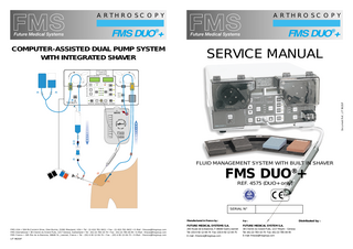
FMS DUO +
SERVICE MANUAL
Document Ref., LIT 9620/F
COMPUTER-ASSISTED DUAL PUMP SYSTEM WITH INTEGRATED SHAVER
FMS DUO +
FLUID MANAGEMENT SYSTEM WITH BUILT IN SHAVER
FMS DUO + ®
REF. 4575 (DUO+ only)
SERIAL N°
FMS USA • 504 McCormick Drive, Glen Burnie, 21061 Maryland, USA • Tel : (1) 410-761-9411 • Fax : (1) 410-761-9422 • E-Mail : [email protected] FMS International • 38 Chemin du Grand-Puits, 1217 Geneva, Switzerland • Tel : (41) 22-783-10-70 • Fax : (41) 22-785-04-95 • E-Mail : [email protected] FMS France • 265 Rte de la Baronne, 06640 St. Jeannet, France • Tel : (33) 4-92-12-04-74 • Fax : (33) 4-92-12-04-75 • E-Mail : [email protected] LIT 9620/F
Manufactured in France by :
For :
FUTURE MEDICAL SYSTEMS S.A.
FUTURE MEDICAL SYSTEM S.A.
265 Route de la Baronne, F-06640 Saint-Jeannet Tel: (33) 4-92-12-04-74 Fax: (33) 4-92-12-04-75 E-mail : [email protected]
38 Chemin du Grand-Puits, 1217 Meyrin - Geneva Tel: (41) 22-783-10-70 Fax: (41) 22-785-04-95 E-mail: [email protected]
Distributed by :
FMS DUO®+
NOTES
SHAVER / DUAL PUMP SYSTEM TABLE OF CONTENTS SECTION 1 INTRODUCTION SYMBOLS AND DESCRIPTION OF PARTS INSTRUMENT DIAGRAM
PAGES 1-3 1-4 1-5
SECTION 2 OPERATIONAL AND VISUAL CHECKS
2-1 to 2-2
SECTION 3 PERFORMANCE CHECKS
3-1 to 3-2
SECTION 4 ELECTRICS ELECTRICAL SECURITY CHECKS ELECTRICAL DISTRIBUTION ELECTRICAL WORKING DIAGRAMS
4-1 4-2 4-3 to 4-4 4-5 to 4-22
SECTION 5 SHAVER HANDPIECE SHAVER HANDPIECE WORKING DIAGRAM SHAVER BLADES
5-1 5-2 5-3
SECTION 6 OPERATION OF THE FOOT-PEDAL BOARD
6-1
SECTION 7 COMPLETE IRRIGATION / ASPIRATION SYSTEM DIAGRAM
7-1
SECTION 8 OPERATING PRECAUTIONS AND CHECKS TROUBLE SHOOTING
8-1 8-2
SECTION 9 SPECIFICATIONS FOR THE FMS DUO®+ SPARE PARTS FOR THE FMS DUO®+
9-1 9-2
SECTION 10 PROPRIETARY INFORMATION AND WARRANTY FORM SAV-06-A (AFTER SALES SERVICE)
10-1 10-2
WARNING • The Manufacturer and Licensed Seller of this device do not accept any liability for direct or consequential damage or injury caused by improper use or usage of disposables other than FMS products. Any alteration to this device, repair from an unlicensed service center or use of non-FMS disposables, will void CE marking, FMS warranty and product liability coverage. • Before servicing the FMS DUO®+, please read this manual completely and follow all instructions carefully. • Failure to follow these instructions may result in potential injury and damage or malfunction of the instrument. FMS DUO® SYSTEM is covered by US patents N° 4902 277, N° 5000 733 and N° 5131 823 European patents N° 0 306 445 and N° 0 448 909 B1, Japanese patent N° 2 107 259. FMS DUO®+ is a registered trademark of FMS © 1997 - Future Medical System S.A. LIT 9620/F
LIT 9620/F
NOTES
1
INTRODUCTION
The FMS DUO®+ combines a pump with a shaver and blade system. The FMS DUO®+ use is indicated for arthroscopic surgery for the following joints: Shoulder, Knee, Wrist, Elbow, Ankle. SERVICE Repairs should only be performed by qualified FMS technicians or at the FMS factory. We must be notified by fax of the date and waybill number of the shipment, please enclose form SAV-06A and a potential diagnosis if you have one . If you cannot be specific on the source of the problem, the malfunction of the instrument should be explained in detail. The information contained in this manual will allow a hospital biomedical engineer or technician to adjust, service and test the instrument. CAUTION Always connect to a properly earthed mains supply. Use FMS recommended cables only. FMS DUO®+ electrical specification : 120/230 V~ ; 50 -60 Hz; 500 VA WARNING The instrument cover should only be removed by a qualified technician when troubleshooting or servicing the unit. The power supply should be disconnected as there is a risk of severe electrical shock if exposed electrical components are touched. No changes should be made to the original design of this unit. Only use FMS recommended replacement parts. Use of any other parts or making changes which alter the original specifications will invalidate the warranty and may create an electrical shock, fire, safety or other hazard. GENERAL PRECAUTIONS 1. Do not use the FMS DUO®+ in the presence of flammable anesthetics or any material that will ignite due to electrical sparking. 2. Use only the appropriate Future Medical Systems disposable Arthroscopy sets and interface cables. 3. The instrument should only be operated by qualified and trained personnel. 4. Do not insert any foreign object into the FMS DUO®+ or in the transducer connector. CAUTION This Instrument is not intended for sale to the general public. No operator should attempt to use the FMS DUO®+ without first studying the Instruction manual. The Quick Manual is only a condensed version of the Instruction Manual and should not be used alone or to train personnel. DELIVERY AND PERIODIC INSPECTION All FMS DUO®+ instruments are checked and guaranteed free of mechanical and electrical defects before leaving our factory. On receiving your instrument, carefully unpack the unit and check for any shipping damage, scratches, dents etc., DO NOT attempt to run the instrument if damaged. Keep a record of all packing material as this may help verify any claim. Immediately notify the shipping company and FMS France. DO NOT return the instrument until the shipping company has inspected it and given authorization. If the Instrument appears to be in good condition proceed with the following inspection procedures. Periodic inspections and testing should be performed at least every six months to ensure safe and correct operation. The following check list should be carried out in the order listed : 1. Mechanical Inspection 2. Functional test 3. Electrical security test
LIT 9620/F 9620/C
LIT 9620/F
1-3
1 FRONT PANEL
1. Transparent safety covers These covers MUST be closed for the roller pumps to rotate. 2. POWER pad Turns the power ON if the main power switch in the back of the pump is on (the green STANDBY light is on). 3. Pressure display This shows the current dynamic pressure. 4. Shaver speed display Indicates the speed as well as the direction of the rotation. 5. Alarm The red indicator will light up if a safety parameter is violated. 6. Tension rocker arms They hold the tubing on the roller pump heads. They are factory set, no alterations should be made by the user. 7. Suction roller pump This roller pump provides outflow of fluid from the joint. 8. Two way Pinch Valve This valve is moved automatically when the foot-pedal is activated; depending on the function requested, one aspiration mode is selected: Normal suction through the cannula. Auxiliary suction through the shaver, basket punch or cannula. 9. Pinch Valve pad This is used to automatically open the pinch valve to place and remove the shaver suction tubing. This will not activate the shaver. 10. Lavage pad This feature automatically sets off a sequence of pressure and flow increases to clear the field of view of blood and debris. Press on the red <LAVAGE> pedal for 2 seonds to initiate the LAVAGE for 2 or 4 minutes. 11. Shaver Speed Selection pads Select the LOW, MED or HIGH pre-set speeds. 12. Shaver Run/Stop pad Used to start the shaver mode when using cutters or burs. 13. Cannula suction setting Indicates the selected flow rate through the cannula. It can be increased or decreased by pressing the CANNULA pad. Adjacent LIT 9620/F
NOTES
SYMBOLS & DESCRIPTIONS OF PARTS indicator lights (MIN, LOW, MED, HIGH) will light up green. The initial setting at power up is MED. Press the blue CANNULA SUCTION foot-pedal to increase suction. Shaver suction setting Indicates the suction rate selected through the shaver, it can be increased or decreased by pressing the SHAVER pad. Adjacent indicator lights (MIN, LOW, MED, HIGH) will light up. The initial setting at power up is LOW. 14. Shaver speed adjustment pads Increase and decrease the shaver RPM. This can also be achieved with the foot-pedal. 15. RUN / STOP pad Turns the pump on and off. If the pump is activated <PUMP> appears on the pressure display. 16. Pressure adjustment pads Press the arrows to increase or decrease the pressure. The initial setting is 50 in increments of 5. 17. Pressure transducer connection A differential transducer is built in the instrument. It measures the pressure in the pressure chamber of the irrigation tubing. 18. FILL CHAMBER pad This is used to automatically fill the chamber and turn off the LOW PRESSURE alarm. 19. Auto-locking device. The patented device allows the disposable tubing to be properly positioned and locked in place around the two roller pumps. For safety reasons it has been color-coded GREEN for the IRRIGATION and ORANGE for the SUCTION tubing. 20. Irrigation roller pump This roller pump provides the inflow of fluid to the joint. 21. Shaver plug To connect the shaver hand-piece
26. Caution Consult the accompanying documents. 27. Equipotentiality symbol.
28. Product conforms to the directive 93/42/EEC
29. Foot-pedal board Four-way color coded foot-pedals to activate the rinse, shaver and lavage modes. 30. Foot-pedal Connection This serves to connect the foot-pedal with the pump. 31. Identification and specifications The specifications of the instrument are indicated on the rear panel. The first 4 digits of the stamped serial number correspond to the year and week of manufacter. 32. Warning Warranty and liability depends on conditions of use. 33. Type B Class 1 Conforms to standard EN 60601-1 34. Waterproof for projections Protected against water projections
HANDPIECE
35. Suction port Connects to shaver suction tubing. 36. Suction toggle switch Controls the amount of suction and should be left completely open when using the shaver. 37. Blade locking ring Rotate the locking ring clockwise and insert blade. Rotate the ring counterclockwise to lock the blade in place. 38. Connector locking ring Slide the locking ring towards the cord to insert or remove the protective cap. REAR PANEL 39. Connector alignment mark Insert the hand-piece into the FMS DUO®+ 22.23.24. I/O Switch, fuses and power with the mark facing upward. socket The on/off switch, fuses and power socket 40. Protective cap Remove the protective cap by holding the are in the same casing (Fuses = 2 x 5 A locking ring and sliding the ring towards time delayed). the cord. While holding the locking ring 25. Shaver connection back, remove the protective cap. Place This is used to connect the connection the cap over the connector end of the cable to the power unit of the shaver. hand-piece before sterilizing or soaking. 1-4
LIT 9620/F 9620/C
10
PROPRIETARY INFORMATION AND WARRANTY
PROPRIETARY INFORMATION Future Medical System S.A. recommends that users of the FMS DUO®+ Fluid Management System study the entire Service and Instruction Manual prior to using , servicing or adjusting the FMS DUO®+. The proper, safe and effective use of the equipment is greatly dependent on the decisions made by the operator and service personnel and cannot be entirely controlled through the design of the equipment. It is imperative that all instructions given in the instruction manual be understood and followed to facilitate and optimize safety to the patient and operator. Future Medical System S.A. deems that all information contained in this manual is proprietary. All information and designs are the property of Future Medical System SA and/or its licensees. Future Medical System S.A. and/or its licensees reserve all patents, copyright and other proprietary rights to this manual including all designs, manufacturing and reproduction. This manual and related material is confidential and shall not be duplicated, in entirety or in part, unless with established written consent of Future Medical System S.A.
1
INSTRUMENT DIAGRAM
FRONT PANEL 1. Transparent Safety Cover
4. Shaver Speed Display
2. Power Pad
20. Irrigation Roller Pump
6. Tension Rocker Arm 7. Suction Roller Pump
3. Pressure Display
5. ALARM
19. Auto Locking Device 8. Two Way Pinch Valve
Future Medical System S.A. has several patents covering both the instrument and its disposable products. 18. Fill Chamber Pad
WARRANTY The FMS DUO®+ Fluid Management System is designed and manufactured using sound engineering practices to provide uninterrupted and dependable service under the most rigorous operating conditions. Should this product fail to provide satisfactory service, contact Future Medical System S.A. after sales service, Nice, France. Future Medical System S.A. guarantees the material and workmanship in the FMS DUO + for ONE YEAR from the date of shipment to the original purchaser. Any unit console failing to perform to material or workmanship standards under this guarantee will be repaired or replaced, at the discretion of Future Medical System S.A., without charge. Future Medical System S.A. liability under this warranty is limited to the above conditions. ®
13. Cannula/Shaver Suction Setting
17. Pressure Transducer Connection
10. Lavage Mode 9. Pinch Valve Pad
15. Pump RUN / STOP Pad 21. FMS Handpiece Connection 16. Pressure Setting Pads
11. Selection Pads
14. Shaver Speed Setting
31. IDENTIFICATION and SPECIFICATIONS
REAR PANEL If you have any questions regarding application of the warranty or service and repair to your FMS DUO®+ Fluid Management System, please contact Future Medical System S.A. at one of the following sales and service centers :
12. Shaver RUN / STOP Pad
33
34
28. Product conforms to the directive 93/42/EEC
26. Caution
27. Equipotentiality symbol
For after sales service, contact : Future Medical Systems S.A. 265 Route de la Baronne 06640 Saint Jeannet, FRANCE Tel : (33) 4-92-12-04-74 Fax : (33) 4-92-12-04-75 E-mail : [email protected]
For Commercial Services : Future Medical System S.A. 38 Chemin du Grand Puits 1217 Meyrin, Geneva, SWITZERLAND Tel : (41) 22-783-10-70 Fax : (41) 22-785-04-95 E-mail : [email protected]
30. Foot Pedal Connection 22. 23. 24. I/O Switch, Fuses and Power Connection
Blue 32. Warning
Red
25. Auxiliary Shaver Connection 29. Pedal Board
HAND PIECE 35. Suction Port
36. Suction Toggle Switch
40. Protective Cap 37. Blade Locking Ring
38. Locking Ring
LIT 9620/F
10-2
LIT 9620/F
39. Connector Alignment Mark
1-5
2
10
OPERATIONAL AND VISUAL CHECKS
1. MECHANICAL INSPECTION
SAV-06-A FAX THIS FORM TO : Future Medical Systems : (33) 4 92 12 04 75
Name/Title of person returning instrument or part :
a) Disconnect instrument from power supply b) Inspect all exterior components, surfaces and corners for damage. An instrument which has been dropped should be disassembled and checked for internal damage by a qualified technician.
Arthro FMS DUO®+ Serial # (on back panel)
Returned with :
2 Way Pedal
Serial #
Interface
Cat. #
Shaver cable
d) Ensure that the handpiece and foot-pedal cables and connectors are in good condition; no cracked insulation or bent pins.
The Mechanical Inspection is complete.
Cat. #
Handpiece Serial #
c) Inspect the power cable; verify that the insulation is intact and that there are no sharp bends or kinks. Damaged cables should be replaced.
e) Ensure that the handpiece and foot-pedal receptacles are clean and do not show signs of excessive ware.
4 Way Pedal
Control Unit
Serial #
If your problem is related to one of the following, please tick appropriate box or provide further information below : Irrigation Pump
Name of institution using instrument :
Suction Pump
2. FUNCTIONAL TESTS No suction from pump
Used for tests : QC test tubing Ref. 4588
Pressure reading incorrect
Switch The FMS DUO®+ on, press POWER and RUN/STOP pump.
Address :
Pinch valve malfunction
Irrigation motor :
Control Pad (please indicate appropriate pad)
• With the LEFT cover down (right cover raised), verify that the motor turns. Suction motor :
Fill Chamber Valve
• With the RIGHT cover down (left cover raised), verify that the motor turns.
Physical damage (describe)
Electrovalve (both covers raised) :
Handpiece
• Press « FILL CHAMBER » pad. The electrovalve should engage for 2 seconds.
Other (explain below)
Pinch valve : • Press « PINCH VALVE » pad. The pinch valve should clamp for 5 seconds. Verification of Pinch Valve occlusion : • Switch on the pump - without tubing • Verify that the Pinch Valve moves completely to the left. • Verify that the pinch valve moves back completely to the right. Verification of Pump Head occlusion :
Please use original FMS DUO®+ packing or pack one instrument per heavy duty cardboard box with adequate protection. Tick here if original packing has been used If parts are returned for standard exchange, please indicate parts returned : Push the tension rocker arm towards finger
• Place a new QC test tubing in position. Occlusion of the Irrigation Pump : • Release the tension rocker adjuster. • Turn the tension rocker adjuster until finger clicks into the groove on the tension rocker arm. • Position the pump head so that the finger on the tension rocker adjuster is aligned with the two rollers. • Check for wear on finger . Occlusion of the Suction Pump :
Irrigation motor
Suction motor
Central unit board
4 Way Pedal
2 Way Pedal
Handpiece
Cat.#
Finger movement 1mm maximum
Instrument or parts to be sent to :
Transportation :
• Carry out the same check for the right tension rocker adjuster.
Serial#
Future Medical Systems S.A. 265 Route de la Baronne, F-06640 St. Jeannet, FRANCE Tel : (33) 4 92 12 04 74 Fax : (33) 4 92 12 04 75
Express carrier
Road
Name of carrier : Reference : Date of shipment :
AWB :
Name/Title of Person returning instrument or part : LIT 9620/F
2-1
LIT 9620/F
Air
Signature : 10-1
9
SPARE PARTS FOR FMS DUO®+ and FOOT-PEDAL BOARD
FMS DUO®+ Ref. 4575 (DUO+ only) and FOOT-PEDAL BOARD Ref. 4176
2
OPERATIONAL AND VISUAL CHECKS (cont’d)
KEYBOARD TESTS, (the FMS DUO®+ is switched on with both covers raised) POWER pad :
ITEM
REFERENCE
Cardboard box and packing
N/A
Chamber support
4900
• Pressing this pad will start the instrument. The LCD « STANDBY » will go out. • Pressing the pad a second time will place the instrument on standby. « STANDBY » will be displayed. • A buzzer will sound twice when the instrument is ready. • Leave the instrument running while carrying out the following tests.
Complete pinch valve (for suction tubing)
4901
RUN/STOP pump pad :
SUB’D male 9 pin connector for foot-pedal
4902
• Pressing this pad once will start the pumps and a buzzer will sound. The LCD display will light up. • Pressing the pad a second time will stop the pumps and a buzzer will sound. The LCD display will go out.
SUB’D 9 pin connector cover
4903
Pressure adjustment (increase) pad :
Complete valve
4904
• Pressing this pad successively will increase the selected pressure level of 5/5 and sound the buzzer. The pressure will be displayed.
Pressure transducer
4906
Pressure adjustment (decrease) pad :
Complete tranformer 120/230 V
4910
• Pressing this pad successively will decrease the selected pressure level of 5/5 and sound the buzzer. The pressure will be displayed.
Complete pressure adjuster
4912
Fill chamber pad :
Tension rocker arm
4913
• Pressing this pad will sound the buzzer and activate the electrovalve.
Complete irrigation motor
4914
Complete suction motor
4915
Rubber foot
4916
Cannula pad : • Pressing this pad successively will sound the buzzer and change the suction flow rate of the cannula. Shaver pad : • Pressing this pad successively will sound the buzzer and change the suction flow rate of the shaver. • RUN/STOP Shaver pad : Guide line
4917
Hinge for safety cover
4918
LCD display with connector
4919
• Pressing this pad will start the shaver and the buzzer will sound. The LCD display will light up. • Pressing the pad a second time will stop the buzzer. The LCD will go out. Preselected shaver speed pads : • When these pads are pressed, the preselected shaver speeds are activated. The buzzer will sound. The corresponding LCD lamp will light up.
Left Lexan safety cover
4921
Right Lexan safety cover
4920
Luer lock
4922
Preselected Shaver speed adjustment pad (decrease) :
PEDDY black foot-pedal cover
4925
• Pressing this pad will decrease preselected shaver speeds.The buzzer will sound.
PEDDY blue foot-pedal cover
4926
PEDDY red foot-pedal cover
4927
Power entry module filter
4928
Sticker “lavage, cannula, reverse, forward”
4930
BUZZER :
Power supply board
4934
The buzzer sounds whenever a pad is pressed.
Plastic spacer (for luer lock)
4923
Metalic spacer (for luer lock)
4924
Complete roller pump head
4932
Preselected Shaver speed adjustment pad (increase) : • Pressing this pad will increase preselected shaver speeds.The buzzer will sound.
Lavage pad : • Pressing this pad successively will sound the buzzer and change the suction lavage selection. The corresponding LCD lamp will light up. Pinch valve pad :
LIT 9620/F
9-2
• Pressing this pad activates the buzzer and the pinch valve clamp.
LIT 9620/F
2-2
3
PERFORMANCE CHECKS
9
FUNCTIONAL TEST FOR PRESSURE SECURITY
DIMENSIONS
Used for test : Test tubing Ref. 4588 Manometer (0 - 1000 mbar)
Height: Width: Depth: Weight:
Low pressure security check : • The pump should be in RUN mode. • Turn the irrigation motor only (left cover down, right cover raised). • Release the right tension rocker adjuster. • A low pressure security alarm will activate if pressure stays at zero for more than 10 seconds. • The LCD ALARM should display and flash « PRES.L » (low pressure). High pressure security check 1 :
SPECIFICATIONS FOR THE FMS DUO®+ Ref. 4575 (DUO+ only)
21 cm 38,5 cm 37 cm 18 kg
PERFORMANCE SPECIFICATIONS Pressure levels (1)(2) : Initial pressure level: Cannula flow rate: Shaver flow rate:
10 - 140 (increments of 5) Precision ± 10% at 0 flow rate 50 100-600 ml/mn (pre-selected) Precision ± 15% of max. flow rate 200 - 800 ml/mn (pre-selected) Precision ± 15% of max. flow rate
• Connect the manometer to the luer lock. • Using the bulbs relayed to the manometer, increase pressure until the LCD ALARM lights up. The LCD ALARM should activate when pressure is at level 150 +/- 10.
Pre-set FLOW (ml/mn)
MIN
LOW
MED
HIGH
High pressure security check 2 :
Cannula Suction
200
300
500
600
• Connect the manometer to the luer lock. • Using the bulbs relayed to the manometer, increase pressure until you hear the relay engage. At this point the pressure reading on the manometer should be : P = 570 +/-5 mbar. • Restart the pump (RUN/STOP pad) press the FILL CHAMBER pad to allow air to enter and verify that the irrigation motor does not turn. • Switch off the pump (POWER pad) and restart to re-initialize the system. • Check that the irrigation motor turns.
Shaver Suction
200
400
600
800
CANNULA FLOW RATE TESTS
Shaver speed:
800 - 4000 rpm (increments of 100)
Pre-set SPEED (rpm)
LOW
MED
HIGH
Shaver speed
800
2000
4000
ELECTRICAL SPECIFICATIONS Input Power: 120 / 230 V~ Frequency: 50-60 Hz Current Draw: 500 VA Fuses: 5 AMP TD Conforms to Standard EN 60601-1 (Electromagnetic Compatibility).
Used for tests : 1 liter graduated beaker Chronometer QC test tubing Ref. 4588 4 Way Foot-Pedal L1. Cannula flow rate (no pedal) : • Activate pumps with test tubing in place. • Place a graduated beaker at tube extremity to recuperate liquid. • Use the graduated beaker to measure amount of liquid produced by suction for 1 minute. • The volume measured should be between 50ml. and 150ml. (100 +/- 50ml/mn.). L2. Cannula flow rate at MINIMUM : • Activate pumps with test tubing in place. • Press pedal « CANNULA SUCTION » • Press pad « CANNULA » to select « CANNULA MIN ». • Use the graduated beaker to measure amount of liquid produced by suction for 1 minute. • The volume measured should be between 150ml. and 250ml. (200 +/-50ml/mn.). L3. Cannula flow rate at LOW : • As for L2 with pad « CANNULA » in position « CANNULA LOW » • The volume measured should be between 225ml. and 375ml. (300 +/- 75ml/mn.). L4. Cannula flow rate at MED : • As for L2 with pad « CANNULA » in position « CANNULA MED » • The volume measured should be between 425ml. and 575ml. (500 +/- 75ml/mn.).
Storage Conditions Temperatures: - 10°C to + 50°C Operating Conditions Temperatures: +10°C to + 40°C Relative humidity: 30 to 75% GENERAL PRECAUTIONS • Use only appropriate Future Medical Systems arthroscopy sets. • Do not connect this device to a power source that is not properly earthed. • Disconnect the device from the main power source when cleaning, servicing or inspecting. • Do not allow this device to run unattended. Patient safety requires that the instrument be continuously monitored during the operation. EMERGENCY INSTRUCTIONS Should the instrument stop working due to a power failure, circuit overload, or other malfunction, disengage the tubing set and control fluid flow via the gravity method. CAUTION ! No operator should attempt to use the FMS DUO®+ without first studying these instructions. The quick manual is only a condensed version of this manual and should not be used to train personnel. CERTIFICATION : • CE 0197 : Directive 93/42/EEC (TÜV Rheinland) • Food and Drug Administration (FDA) under 510(K) classification.
L5. Cannula flow rate at HIGH : • As for L2 with pad « CANNULA » in position « CANNULA HIGH » • The volume measured should be between 525ml. and 675ml. (600 +/- 75ml/mn.). LIT 9620/F
3-1
(1) Pressure measured in pressure reservoir (2) For a level of 50, the pressure (1) in millimeters of mercury should be 112,5 ± 10%
LIT 9620/F
9-1
8
3
TROUBLE SHOOTING CAUSE
POSSIBLE SOLUTIONS
• No irrigation.
• The stop-cock on the arthroscope or one of the clamps is closed. • No outflow
• Check the inflow line from the bags to the joint. Open any closed clamps or stop cocks.
• The irrigation pump starts spinning frantically, excessive noise.
• No more irrigation fluid
• Replace saline bags and/ or check the clamps under the bags. • Press FILL CHAMBER
• The irrigation pump goes on and off erratically. • Abnormal pressure fluctuation.
• The pre-set pressure may be too close to the high pressure safety. • Water might have entered into the pressure sensing line.
• Lower the pressure.
• Air leak in the line.
• Check that the luer locks on the intermediary and pressure sensing tube are closed. • Change the irrigation tubing and start again.
PROBLEMS
• Too much water in the pressure chamber.
• Persistent air leak in the line. • Insufficient pressure.
• Irrigation problem.
• Change the irrigation tubing.
• Check the stop cock on the arthroscope, the clamps under the saline bags and under the pressure chamber.
PERFORMANCE CHECKS (cont’d)
SHAVER FLOW RATE TESTS Used for tests : 1 liter graduated beaker Chronometer QC test tubing Ref. 4588 4 Way Foot-Pedal M1. MIN shaver flow rate : • Activate pumps with QC test tubing in place. • Press pad « SHAVER » to select « SHAVER MIN ». • Place a graduated beaker at tube extremity to recuperate liquid. • Press « FORWARD » or « REVERSE » pedal. • Use the graduated beaker to measure amount of liquid produced by suction for 1 minute. • The volume measured should be between 150ml. and 250ml. (200 +/- 50ml/mn.). M2. LOW shaver flow rate : • As for MI with pad « SHAVER » in position « SHAVER LOW » • The volume measured should be between 325ml. and 475ml. (400 +/- 75ml/mn.). M3. MED shaver flow rate : • As for MI with pad « SHAVER » in position « SHAVER MED » • The volume measured should be between 525ml. and 675ml. (600 +/- 75ml/mn.). M4. HIGH shaver flow rate : • As for MI with pad « SHAVER » in position « SHAVER HIGH » • The volume measured should be between 725ml. and 875ml. (800 +/- 75ml/mn.). PRESSURE TRANSDUCER TESTS
• Insufficient irrigation.
• The cannula has been incorrectly placed (in the sub-cutaneous tissues) or is obstructed. • One of the covers is open.
• Reposition or clean the cannula
• The pump stops.
• The HIGH PRESSURE safety has gone off.
• Close the covers. • Modify the conditions of operation. • Press on the RUN/STOP pad to restart the pump. • Check the position of the pressure chamber and the tubing going to the pressure chamber. • (See ALARM on page 8) • Press on FILL CHAMBER to stop the alarm and press on the RUN/STOP pad to restart the pump. • Check if luer lock is tight.
• The LOW PRESSURE safety has gone off : “LOW PRESSURE” blinks.
• No suction.
• The cannula is obstructed. • The shaver blade is obstructed. • The pinch valve is not operating.
• Reposition or clean the cannula. • Dismantle the blade and clean it. • Check the positioning of the suction tubing.
Used for tests : Digital Manometer Chronometer QC test tubing Ref. 4588 J1. Pressure transducer leak tests : • Activate pumps with QC test tubing in place. • Raise the preselected pressure to 140 +/- 5 feet H2O. This will appear on the display. • Raise both covers, the motors should stop. • Place the roller pump heads manually with regard to the fingers to achieve maximum watertightness. • The pressure should stay at the same rate for one hour. • Note the pressure level after one hour. The pressure displayed should not vary more than 2 feet H2O. K1. Pressure transducer tests : • With the pump working, raise both covers. • Connect the manometer to the luer lock. • Using the bulbs on the manometer, introduce the pressure reference in feet H2O. Note the exact value displayed. • Pressure reference = 50 +/- 5 feet H2O. • Measure real pressure with the manometer and note value. • Compare these values with the pressure reference. The difference between the displayed pressure reference on the pump and that read on the manometer should not be more than 5% of the pressure reference. Attention : The value read on the manometer is in mbar. Use the following formula to convert mbar into feet H2O :
• Check that the main power switch on the back of the pump is on the I position and that the RUN/STOP pad green light is on. • Check that both covers are closed.
• Set the switch on I and on RUN
Feet H2O = Value in mbar displayed on the manometer 2,9993
• Close the covers and restart.
K2.Pressure transducer tests : • Pressure reference = 75 +/- 5 feet H2O • Same operation as K1
• Blades continue to rotate when pedal is released.
• Circuit problem
• Turn off unit (I/O switch, see 22, 23, 24 instrument diagram page 5)
K3. Pressure transducer tests : • Pressure reference = 100 +/- 5 feet H2O • Same operation as K1
• Insufficient R.P.M. regardless of setting.
• Circuit problem
• Turn off unit (I/O switch, see 22, 23,24 instrument diagram page 5)
K3. Pressure transducer tests : • Pressure reference = 125 +/- 5 feet H2O • Same operation as K1
• The pump heads don’t rotate.
LIT 9620/F
8-2
LIT 9620/F
3-2
4
8
ELECTRICS
OPERATING PRECAUTIONS AND CHECKS
DAILY MAINTENANCE OF THE FMS DUO®+ At the end of the operating day, switch the FMS DUO®+ off, unplug the power cord and discard all tubing. Wipe off the instrument’s sides, front panel and covers with a soft cloth that has been slightly moistened with a neutral-pH detergent. Wipe again using distilled water to rinse. DO NOT IMMERSE FOOT-PEDAL BOARD / CLEANING AND DECONTAMINATION After each operation, clean the foot-pedal and the power cord with a neutral-pH detergent. The foot-pedal board is waterproof except for the electrical connection which must remain dry. DO NOT AUTOCLAVE • Do not twist the cable when storing • Do not unplug instrument by pulling on cable PRE-OPERATIONAL / WEEKLY CHECKS 1. 2. 3. 4. 5.
Examine the power cord for any damage or deterioration. Check that the roller heads rotate freely on their axes. Check that the pressure transducer is free of debris. Check that the connectors on the back of the pump are not damaged and free of debris. Check that the pinch valve moves freely by pressing on the PINCH VALVE pad (the pump must be in the RUN mode to activate the pinch valve). 6. Check foot-pedal springs. PUMP SET-UP / OPERATIONAL CHECKS 1. Place the FMS DUO®+ preferably near the video cart at the same level as the patient. 2. Connect the foot-pedal to its connection on the rear panel of the pump, and place it under the table next to the person responsible for its operation. 3. Connect the pump to a power source of the right voltage and correct earth. Turn the main power switch to I on the back of the unit. Open the covers. 4. Turn the pump on by pressing on the POWER pad (2), (the covers must be open); the LCD screen will light up. 5. Check the pressure pre-set level by pressing the pressure increase or decrease pads (16); the initial setting at power up is level 50. 6. Increase the pre-set pressure by pressing the pressure increase pad ▲ (16). The LCD display shows 55 (preset pressure) for 2 seconds and then displays “Pump 4000”. 7. Decrease the pre-set pressure to level 45 by pressing the ▼ pad. 8. At power up, the cannula suction should be at the MED setting; the shaver suction as well as the lavage mode should be in the LOW setting. Press the CANNULA suction pad and note that the LCDs light up sequentially (MIN, LOW, MED, HIGH); follow the same procedure for the SHAVER suction. 9. Press POWER pad to reset suction and lavage to the initial settings or to the surgeon’s preference. 10. Press the PINCH VALVE pad (9) and check to see if the plastic piece moves freely; wait 5 seconds and the pinch valve will return to its initial position (the instrument must be in the RUN mode to activate the pinch valve). 11. Close both covers, the roller pumps should rotate when the covers are closed. Turn off the pump with the RUN/STOP pad if the pump functions correctly. 12. Press the REVERSE or FORWARD foot-pedal and control the movement of the Pinch Valve (the pump must be in the RUN mode (15) to activate the Pinch Valve) and check that the green light on the SHAVER side is blinking. 13. Press the blue CANNULA SUCTION foot-pedal. It will not activate the Pinch Valve but will cause the green light on the CANNULA side to blink. 14. WARNING ! Do not run the pump continuously without tubes around the roller heads. REPLACING THE FUSES (2 X 5A Time Delay) The fuses are housed in the mains switch assembly (22) on the back panel. 1. Disconnect the power cord. 2. Pull the fuse drawer out fully and swing down to access the two fuses. 3. Replace the defective fuses (check that they are correctly placed), swing the drawer up and push back fully into its housing.
LIT 9620/F
4-1
LIT 9620/F
8-1
7
COMPLETE IRRIGATION / ASPIRATION SYSTEM
4
ELECTRICAL SECURITY CHECKS
EARTH BOND TEST Carry out an earth bond test according to the standard EN60601-1-1- (Class 1 type B) Current test : l = 25A Use a Bio-Tek Instrument, Model 601 or equivalent. Measure the resistance value. The meter should measure less than 0.2 ohm. If greater than 0.2 ohm the mains cable or chassis wiring may be damaged. The FMS DUO®+ should be serviced before being used. CURRENT LEAKAGE TEST These instructions give the method used for the current leakage test of the FMS DUO®+ to the directive EN 60601-1. Used for test : Electronic security device Bio-Tek instrument, model 601 or equivalent. The FMS DUO®+ should be tested with : • FMS DUO®+ mains cable. • Test tubing. • The handpiece equipped with bur and cable. • The test pedal board. Connect the suction tubing to the suction socket on the hand piece. Note :
The handpiece should be connected to the FMS DUO®+ to be tested (front panel). The handpiece stop-cock should be opened to maximum. The handpiece should be tested with a bur.
Check the following before testing : • The correct fuses are installed. • The casing is securely screwed down. • The mains switch is in the « I » position. • The mains cable is properly connected to the FMS DUO®+ being tested. • Connect the mains cable of the instrument to the test socket of the 601 PRO. • Connect the red test conductor on the red terminal of the 601 PRO to the earth contact on the FMS DUO®+. Verify that the main menu of the 601 PRO is displayed. Switch on the FMS DUO®+ to be tested (the mains switch is in the « I » position). Close both covers. The 601 measures the following : • Mains tension (Ph-Earth / Ph-N). • Earth resistance, I =25 A (R<0.200Ω). • Isolation resistance (R>2MΩ) • Current consumption. • Current leak to earth (<500 µA in CN and <1000 µA in CPD). • Current leak through cover (<100 µA in CN and <500 µA in CPD). • Current leak to patient (<100 µA in CN and <500 µA in CPD). Current leaks are measured in normal conditions (CN), and simulated first fault (CPN), in normal and inverted polarity. ISOLATION RESISTANCE These instructions show the method that should be employed during the final isolation test of the FMS DUO®+. Used for test : Megaohmeter High threshold : 200 GΩ ® The FMS DUO + should be tested with its mains cable. Check the following before testing : • The correct fuses are installed. • The casing is securely screwed down. • The mains switch is in the « I » position. • The mains cable is properly connected to the FMS DUO®+ being tested. Connect the Megaohmeter wire to the earth contact on the back panel of the FMS DUO®+. Connect the two wires with their clips to the neutral and positive wires of the mains cable of the FMS DUO®+. Apply tension of 500 V during 5 sec. The insulation resistance measured with the aid of the Megaohmeter, should be R>2MΩ. LIT 9620/F
7-1
LIT 9620/F
4-2
4
6
ELECTRICAL DISTRIBUTION
OPERATION OF THE FOOT-PEDAL BOARD
Future Medical Systems has developed a foot-pedal board which controls the Dual Pump System and its shaver. When the pedal is not activated the normal suction rate is 100ml/mn.
TRANSFORMER
CAUTION: Only use LAVAGE MODE with adequate outflow. Use an FMS 4.5mm Outflow Cannula Ref. 1580. PRESS ON THE FOOT PEDAL
TRANSFORMER (viewed from above)
ACTION ON THE SHAVER
Black
70mm
The brown and white 0-115V wires should be passed through and around the ferrite tube (A), three times.
Blue
Reverse
Red
SHAVER ROTATION SENSE
Internal mains connection cable
A
SUCTION THROUGH
Forward
B
Oscillate
180mm
Connection of the 5 point primary junction : 1 - Grey wire 115V 2 - Brown wire 115 V 3 - Black wire 0V 4 - White wire 0V
NO SUCTION
SPEED DECREASE
NO SUCTION
SPEED INCREASE
BOTH
BOTH
INCREASED SUCTION
SUCTION
360mm
SHAVER ROTATION SPEED
BOTH
The black and grey 0-115V wires should be passed through and around the ferrite tube (B), three times.
NONE Increased suction by cannula at the pre-set level
START LAVAGE
Connection of the 4 point secondary junction :
NONE
LAVAGE
1 - 34V Red wire 2 - 34V Red wire 3 - 15V Blue wire 4 - 15V Blue wire
IMPULSE (2 sec)
Increased pressure and intermittent variation of flow
STOP LAVAGE (before end of cycle) NONE IMPULSE (2 sec)
LIT 9620/F
4-3
LIT 9620/F
Return to normal suction 100ml/mn
6-1
5
4
SHAVER BLADES
FMS shaver blades are designed for limited re-use. The blades are manufactured with 100% medical grade stainless steel and the adapters are of re-usable and autoclavable plastic (FMS shaver blades are compatible with LINVATEC, FRIATEC and ARTHREX shavers).
ELECTRICAL DISTRIBUTION (cont’d)
FMS DUO®+ ELECTRICAL DISTRIBUTION PLAN (viewed from above)
1. 1. Outer blade 2. Tab to track number of uses 3. Ring - colour indicates the type of blade 4. Locking pin
1
3
2
4
7 2.
5. Inner blade 6. Cap - the colour indicates 5 the type of blade 7. Body - colour indicates blade diameter : Light grey = 3,5 mm White = 4,0 mm Dark grey = 5,0 mm Black = 5,5 mm
4. 7
3.
6
Note : Colour of Ring #3 and Cap #6 should always match.
• The inner blade must be removed from the outer blade for cleaning and sterilization. To do so, grasp the end of the inner blade and pull it until it snaps out of the outer blade. • To re-insert the inner blade into the outer blade, push until a click is heard, indicating that it has snapped into place. Match color coding of inner and outer blades to reassemble. Before and after each use, disassemble the inner blade from the outer blade and clean the blades using FMS brushes (see page 19) with a mild pH balanced detergent. Ensure that all components are free from blood, tissue, fats or foreign materials. Immerse blades in a solution of water and detergent/decontaminant, refer to detergent instructions for length of immersion time. Rinse well with water and dry. NOTE: The blades can be re-used and re-sterilized until cutting efficiency is no longer appropriate. FMS recommends re-using the same blade a maximum of five times.
8.
SHAVER INSTRUCTIONS • Press on the shaver RUN/STOP pad (12). • When the control unit is switched on, 2000 RPM appears in the display. • The
selection pad (11) gives a pre-set speed of 800 rpm which is recommended for 3.5mm CUTTERS.
10. 1. 2. 3. 4. 5.
LIT 9620/F
5-5
Mother board Combined fuse/mains switch assembly Mains circuit board Transformer Suction motor
MAINS CABLE SPECIFICATION (external) Ref : Material : Tension : Connector : Specification : Cable : Homologation :
• Pressing the (2000 rpm) or (4000 rpm) selection pads (11) provides pre-set speeds for use with BURS • The maximum oscillating speed for CUTTERS is 1500 rpm. • The rotation speed can be set by pressing the or pads (14) or by using the foot-pedal (see instructions). • Blade rotation is activated by pressing the foot-pedals as described on page 16.
7. 9.
SHAVER BLADE DISINFECTING / STERILIZATION • STEAM STERILIZATION 134°C for 18 minutes. • ETO STERILIZATION The blades can also be Ethylene Oxide (gas) sterilized using the hospital’s operating parameters for the gas and aeration cycles. NOTE: These guidelines do not guarantee that the device is sterile after the procedure. The institution is responsible for sterility assurance validation.
5.
6.
CLEANING / DECONTAMINATION
Specification : Color : Length : LIT 9620/F
Cord 6-21 DDG 2,5 PVC Current 10/16 A 250 VAC Dia. 4.8 mm EEC 7 Vll H05 VVF 3GO,75 VDE K S N D FI EEC 22 V Grey 2,5 m 4-4
6. 7. 8. 9. 10.
Irrigation motor Pinch valve Electrovalve Display Keyboard
4
LIT 9620/F
ELECTRICAL WORKING DIAGRAMS
4-5
5
SHAVER HAND-PIECE REFERENCES
DIAGRAM REF.
ITEM
REFERENCE
1
Body
98-151030
2
Complete output shaft
98-2-51000
3
Coupling hub
98-1-51140
4-5
Allen screws
DIN913 M2. 5x3 A2 stainless steel
6
Complete motor
B0912H4877
7
Complete connector
98-2-51020
8a-8b
Nuts
98-1-51150
9
Protection cap
98-1-51130
10
Suction tube
98-1-51090
11
Control valve
98-1-51110
12
Control valve handle
98-1-51100
13
Allen screws
DIN913 M2x5 A2 stainless steel
14
O-Ring
14x1.78 EPDM
15
Locking system
98-1-51050
16-17
Locking system screws
98-1-51060
18
Locking ring
98-1-51040
19-20-21
Springs
98-1-51080
22-23-24
Contact washers
98-1-51070
25-26-27
Stainless steel ball bearings
Ø3
28-29
Allen screws
DIN912 M2x4 A4 stainless steel
32
Teflon strip
N/A
33
O-Ring
4x1 EPDM
34
Sleeve
98-1-51260
LIT 9620/F
5-4
4
ELECTRICAL WORKING DIAGRAMS (cont’d)
5
SHAVER HANDPIECE OPERATING INSTRUCTIONS
WARNING: Prior to use, the system components should be checked for any damage. Do not use if any damage is apparent. • Plug the power cord into the wall outlet and the back of the FMS DUO®+. • Plug the pedal board into the back of the FMS DUO®+. • Switch on the control unit by setting the main power switch (I/O at rear of instrument) to the I position. • Insert the hand-piece connection cable into its port on the front panel of the FMS DUO®+.
CONNECTING THE SHAVER HANDPIECE NON-STERILE ZONE
NON-STERILE ZONE
STERILE ZONE
STERILE ZONE
SHAVER
FMS
Hold here while removing cap and when disconnecting from front panel
1. Receive the shaver connector from the sterile field.
ARTHRO FMS ®+ SHAV ER
Future Medical Systems
POWER
SPEED ADJUST
SPEED PRE-SET
STANDBY
LOW
M ED
HIGH
NEVER PULL ON CABLE
2. Hold the connector and remove cap, align red dots and connect to front panel.
3. Insert the shaver tubing onto the shaver suction port.
4. Insert shaver blade. Open suction toggle to MAX.
LOADING SHAVER-BLADES INTO THE HANDPIECE STEP 1 OPEN Rotate the blade ring clockwise.
STEP 2 Hold the locking ring, align the blade guide with the slot on the handpiece, insert blade into the handpiece.
STEP 3 CLOSE Release the blade locking ring or rotate counter-clockwise to secure the blade To open suction stop-cock, turn the suction toggle clockwise. To close it, turn the toggle counter-clockwise
HANDPIECE CLEANING & DECONTAMINATION 1. Disconnect the instrument from the main power supply. 2. Place the protective cap securely onto the cable to shaver connection (9 pin plug). 3. Leave the suction control in the MAX position. 4. Wipe the console and hand-piece with a neutral detergent/decontaminant solution. 5. Clean the drainage tube with a brush. 6. Rinse thoroughly and dry. NOTE: Do not use any cleaning products containing hydroxide. They will damage the anodized aluminum coating.
HANDPIECE DISINFECTING / STERILIZATION The handpieces are factory sealed and are completely sterilizable using either a steam autoclave, ETO, or soaking. • STEAM STERILIZATION OF ARTHRO FMS® SHAVERS: Steam at 134°C for 18 minutes. • SOAKING: The handpiece may be immersed in a chemical disinfecting bath (such as CIDEX) for cleaning and disinfecting. Refer to the manufacturer’s instructions. Cold soak “sterilants”are not recommended as a method of choice because of extended time required for effectiveness. Extended soaking of instruments that contain dissimilar metals may lead to electrolytic corrosion. NOTE: These guidelines do not guarantee that the device is sterile after the procedure. The institution is responsible for sterility assurance validation.
LIT 9620/F
4-7
LIT 9620/F
5-2