Service Manual
674 Pages
Preview
Page 1
To obtain information about a warranty, if any, contact Covidien Technical Services at 1.800.635.5267 or your local representative. Purchase of this instrument confers no express or implied license under any Covidien patent to use the instrument with any ventilator system that is not manufactured or licensed by Covidien.
Copyright information Copyright 2013 Covidien. All rights reserved. The Puritan Bennett™ 840 Ventilator System is manufactured in accordance with Covidien proprietary information. U.S. Patents 5,271,389; 5,319,540; 5,339,807; 5,771,884; 5,791,339; 5,813,399; 5,865,168; 5,881,723; 5,884,623; 5,915,379; 5,915,380; 6,024,089; 6,161,539; 6,220,245; 6,269,812; 6,305,373; 6,360,745; 6,369,838; 6,553,991; 6,668,824; 6,675,801; 7,036,504; 7,117,438; RE39225. COVIDIEN, COVIDIEN with logo, the Covidien logo and positive results for life are U.S. and internationally registered trademarks of Covidien AG. All other brands are trademarks of a Covidien company. The information contained in this manual is the sole property of Covidien and may not be duplicated without permission. This manual may be revised or replaced by Covidien at any time and without notice. You should ensure you have the most current applicable version of this manual; if in doubt, contact the Technical Support Department of Covidien or your local representative. While the information set forth herein is believed to be accurate, it is not a substitute for the exercise of professional judgment. The ventilator should be operated and serviced only by trained professionals. Covidien’s sole responsibility with respect to the ventilator, and its use, is as stated in the limited warranty provided. Nothing in this manual shall limit or restrict in any way Covidien’s right to revise or otherwise change or modify the equipment (including its software) described herein, without notice. In the absence of an express, written agreement to the contrary, Covidien has no obligation to furnish any such revisions, changes, or modifications to the owner or user of the equipment (including its software) described herein.
Manufacturer: Covidien llc 15 Hampshire Street Mansfield, MA 02048 USA Phone: +800.255.6774
Authorized Representative: Covidien Ireland Limited IDA Business & Technology Park Tullamore
Preface
Definitions This manual uses three special indicators to convey information of a specific nature. They include: Warning Indicates a condition that can endanger the patient or the ventilator operator.
Caution Indicates a condition that can damage the equipment.
NOTE: Indicates points of particular interest that make operation of the ventilator more efficient or convenient.
Warnings, cautions, and notes Please take the time to familiarize yourself with the following caveats as they cover safety considerations, special handling requirements, and regulations that govern the use of the Puritan Bennett™ 840 Ventilator System. • To ensure proper servicing and avoid the possibility of physical injury, only qualified personnel should attempt to service or make authorized modifications to the ventilator. • To prevent possible personal injury and equipment damage, make sure the brakes on the casters are set to prevent inadvertent movement of the ventilator during service. • The user of this product shall have sole responsibility for any ventilator malfunction due to operation or maintenance performed by anyone not trained by Covidien staff. • To avoid an electrical shock hazard while servicing the ventilator, be sure to remove all power to the ventilator by disconnecting the power source and turning off all ventilator power switches. • To avoid a fire hazard, keep matches, lighted cigarettes, and all other sources of ignition (e.g., flammable anesthetics and/or heaters) away from the Puritan Bennett 840 Ventilator System and oxygen hoses. Do not use oxygen hoses that are worn, frayed, or contaminated by combustible materials such as grease or oils. (Textiles, oils, and other combustibles are easily ignited and burn with great intensity in air enriched with oxygen.) In case of fire or a burning smell, immediately disconnect the ventilator from the oxygen supply, facility power, and BPS. • When handling any part of the Puritan Bennett 840 Ventilator System, always follow your hospital infection control guidelines for handling infectious material. Covidien recognizes cleaning, sterilization, sanitation, and disinfection practices vary widely among healthcare institutions. It is not possible for Covidien to specify or require specific practices that will meet all needs, or to be responsible for the effectiveness of cleaning, sterilization, and other practices carried out in the patient care setting. Covidien does recommend users of its products that require cleaning and sterilization/ disinfection consider the National Standards and Recommended Practices for Sterilization published by the Association for the Advancement of Medical Instrumentation (AAMI), as well as the following Center for Disease Control (CDC) publications: Guidelines for Maintenance of In-use Respiratory Therapy Equipment and Guidelines for Prevention of Nosocomial Pneumonia.
ii
Preface
• Patients on life-support equipment should be appropriately monitored by competent medical personnel and suitable monitoring devices. • The Puritan Bennett™ 840 Ventilator System is not intended to be a comprehensive monitoring device and does not activate alarms for all types of dangerous conditions for patients on life-support equipment. • For a thorough understanding of ventilator operations, be sure to thoroughly read the Puritan Bennett™ 800 Series Ventilator System Operator’s and Technical Reference Manual before attempting to use the system. • Before activating any part of the ventilator, be sure to check the equipment for proper operation and, if appropriate, run SST (Short Self Test). • Do not use sharp objects to make selections on the graphical user interface (GUI) display or keyboard. • Federal law (U.S.) restricts the sale of this device to, or by the order of, any physician. • Check the ventilator periodically as outlined in this manual; do not use if defective. Immediately replace parts that are broken, missing, obviously worn, distorted, or contaminated. • An alternative source of ventilation should always be available when using the Puritan Bennett 840 Ventilator System.
Year of manufacture The year of manufacture for ventilators whose serial numbers begin with 4200 is indicated on the rear panel of the BDU as shown here. The two digit number following the year indicates the month of manufacture.
2003 – 10 For ventilators whose serial numbers begin with 3510, the year of manufacture is indicated by the serial number’s 5th and 6th digits. In the example below, a ventilator with serial number 3510021223 was the 1223rd unit built in 2002.
3510 02 1223 Sequential number Year of manufacture
iii
Preface
Electromagnetic susceptibility The Puritan Bennett™ 840 Ventilator System complies with the requirements of IEC 60601-1-2 (EMC Collateral Standard), including the E-field susceptibility requirements at a level of 10 volts per meter, at frequencies from 26 MHz to 1 GHz, and the ESD requirements of this standard. However, even at this level of device immunity, certain transmitting devices (cellular phones, walkie-talkies, cordless phones, paging transmitters, etc.) emit radio frequencies that could interrupt ventilator operation if located in a range too close to the ventilator. It is difficult to determine when the field strength of these devices becomes excessive. Practitioners should be aware radio frequency emissions are additive, and that the ventilator must be located a sufficient distance from transmitting devices to avoid interruption. Do not operate the ventilator in a magnetic resonance imaging (MRI) environment. Chapter 7 describes possible ventilator alarms and what to do if they occur. Consult with your institution’s biomedical engineering department in case of interrupted ventilator operation and before relocating any life support equipment. Warning Accessory equipment connected to the analog and digital interfaces must be certified according to IEC 60601-1. Furthermore, all configurations shall comply with the system standard IEC 60601-1-1. Any person who connects additional equipment to the signal input part or signal output part of the Puritan Bennett 840 ventilator configures a medical system, and is therefore responsible for ensuring the system complies with the requirements of the system standard IEC 60601-1-1. If in doubt, consult Covidien Technical Support at 1.800.255.6774 or your local representative.
Customer assistance If you require further assistance, contact Covidien at 1.800.255.6774 or your local Covidien representative.
Additional information For online technical support, visit the SolvITSM Center Knowledge Base at http://www.puritanbennett.com. The SolvIT Center provides answers to frequently asked questions about the Puritan Bennett 840 Ventilator System and other Covidien products 24 hours a day, 7 days a week.
About this manual This manual provides information needed to service the Puritan Bennett 840 Ventilator System. This manual is intended for use by certified biomedical engineering technicians or personnel with equivalent experience and training in servicing this type of equipment. It is recommended the user complete the Covidien training class geared specifically to the Puritan Bennett 840 Ventilator System. While this manual covers the ventilator configurations currently supported by Covidien, it may not be all-inclusive and may not be applicable to your ventilator. You should ensure you have the most current applicable version of this manual; if in doubt, contact Covidien or visit the Covidien product manual Web page at http://www.puritanbennett.com/serv/manuals.aspx Some illustrations and photos are shown with a ready-to-assemble (RTA) cart, Puritan Bennett 800 Series Ventilator Compressor Mount Cart or a Puritan Bennett 800 Series Ventilator Pole Cart. Please note these images are for illustrative purposes only, and regardless of which cart you have, the required information is provided. The term “RTA cart” refers to the ready-to-assemble cart and any earlier cart versions. Within the USA, contact Covidien at 1.800.255.6774 for questions regarding the applicability of the information.
iv
SECTION
Table of Contents 1
General Information 1.1 1.2 1.3 1.4 1.5 1.6 1.7 1.8 1.9 1.10 1.11 1.12 1.13 1.14 1.15
2
How to use this manual ... 1-1 General product description... 1-1 Configuration information ... 1-2 Accessories ... 1-3 Specifications ... 1-4 Compliance and approvals... 1-8 1.6.1 Manufacturer’s Declaration ... 1-10 Technical information ... 1-15 Range, resolution, accuracy, and new patient/default settings ... 1-18 Tools, equipment, and service materials... 1-29 Periodic maintenance ... 1-34 Service kits ... 1-35 Controls and indicators ... 1-37 Onscreen symbols and abbreviations... 1-58 Ventilator serial numbers and software version ... 1-58 Service philosophy... 1-58
Theory of Operation 2.1
2.2 2.3
2.4
2.5
Major ventilator subassemblies ... 2-1 2.1.1 Breath delivery unit (BDU) ... 2-2 2.1.2 Graphic user interface (GUI)... 2-3 2.1.3 806 Compressor Unit... 2-4 2.1.4 802 or 803 Backup Power Source (BPS) ... 2-4 2.1.5 Cart ... 2-5 2.1.6 Patient system ... 2-6 Operational overview ... 2-7 Pneumatic system ... 2-11 2.3.1 Inspiratory module... 2-16 2.3.2 Patient System... 2-35 2.3.3 Exhalation module... 2-37 2.3.4 806 Compressor Unit... 2-42 Electrical system ... 2-47 2.4.1 Summary of electrical components... 2-47 2.4.2 Overview of electrical system operation ... 2-52 2.4.3 AC distribution components ... 2-57 2.4.4 Power supply ... 2-61 2.4.5 BPS ... 2-63 2.4.6 Card Cage ... 2-65 2.4.7 Data key subsystem... 2-76 2.4.8 GUI ... 2-76 2.4.9 BDU LED PCBA ... 2-91 2.4.10 Inspiratory module PCBA... 2-91 2.4.11 Exhalation transducer PCBA... 2-93 2.4.12 806 Compressor unit ... 2-95 Breath delivery ... 2-104
v
Table of Contents
2.6
2.7
3
Self Tests 3.1 3.2 3.3
3.4
3.5
3.6
4
Introduction... 3-1 How to enter Service Mode ... 3-1 Self tests and background checks ... 3-1 3.3.1 POST (Power On Self Test)... 3-1 3.3.2 SST (Short Self Test) ... 3-1 3.3.3 EST (Extended Self Test) ... 3-2 3.3.4 Background checks ... 3-2 3.3.5 When self tests are run... 3-2 Power on self test (POST)... 3-4 3.4.1 Safety ... 3-7 3.4.2 POST characteristics ... 3-7 3.4.3 POST following power interruptions... 3-8 3.4.4 POST user interface... 3-8 3.4.5 Structure of POST ... 3-9 SST (short self test) ... 3-12 3.5.1 When to run SST ... 3-13 3.5.2 Hardware requirements ... 3-14 3.5.3 Running SST ... 3-15 EST (extended self test)... 3-19 3.6.1 Description of EST ... 3-19 3.6.2 When to run EST ... 3-19 3.6.3 Hardware requirements ... 3-20 3.6.4 How to run EST ... 3-20 3.6.5 How to run Single Test EST ... 3-28
Service Mode 4.1 4.2
vi
2.5.1 Inspiration ... 2-104 2.5.2 Exhalation ... 2-106 Other hardware operations ... 2-109 2.6.1 Gas supply and control ... 2-109 2.6.2 Data monitoring ... 2-109 2.6.3 Pressure transducer autozero ... 2-111 2.6.4 Power monitoring and power fail handling ... 2-113 Emergency modes of operation ... 2-115 2.7.1 Safety valve open (SVO) state ... 2-115 2.7.2 Occlusion handling ... 2-117
Accessing Service Mode ... 4-1 Service Mode functions ... 4-3 4.2.1 SST RESULT: Displaying SST results ... 4-5 4.2.2 DIAG LOG: Displaying diagnostic or event and status logs... 4-5 4.2.3 Alarm log: Displaying the alarm history ... 4-7 4.2.4 VENT CONFIG: Displaying software revisions and serial numbers ... 4-7 4.2.5 OPERATION TIME: Displaying ventilator and compressor elapsed hours.. 4-7 4.2.6 TEST SUMMARY: Displaying results from EST and SST ... 4-7 4.2.7 EST: Extended self test... 4-7 4.2.8 DATE/TIME: Adjusting date and time ... 4-7 4.2.9 EXIT: Exiting Service Mode ... 4-8
Table of Contents
4.2.10 4.2.11 4.2.12
5
Performance Verification 5.1 5.2 5.3 5.4 5.5 5.6 5.7
5.8
6
Other screens... 4-8 Automatically executed Service Mode functions... 4-17 Oxygen sensor calibration ... 4-20
Tools, test equipment, and service materials ... 5-1 When to run ... 5-1 Preliminary ventilator cleaning and inspection... 5-4 Preliminary ventilator setup ... 5-4 Preliminary calibrations and tests ... 5-5 Performance verification guidelines ... 5-7 Performance verification tests... 5-7 5.7.1 Electrical safety test ... 5-8 5.7.2 Ground isolation check... 5-8 5.7.3 Extended self test (EST) ... 5-9 5.7.4 Regulator pressure verification... 5-10 5.7.5 Serial loopback test (10.4-inch GUI only)... 5-11 5.7.6 Using PTS 2000 Performance Test System and BreathLab 840 VTS software5-12 5.7.7 Manual ventilator check using alternate equipment ... 5-16 Regulator calibration hose repair instructions ... 5-17
Diagnostic Codes 6.1 6.2 6.3 6.4 6.5 6.6
Introduction... 6-1 Reference Tables ... 6-1 Troubleshooting ... 6-2 POST fault handling ... 6-2 Diagnostic CPU LED arrays ... 6-3 Diagnostic codes... 6-4 6.6.1 How to interpret diagnostic codes ... 6-4 6.7 Organization of diagnostic codes table... 6-5 6.8 System Diagnostic Log and BDU POST analog devices test ... 6-76 6.9 Diagnostic codes for POST faults... 6-78 6.9.1 POST interrupt errors and test failures... 6-86 6.10 SST and EST test sequences and diagnostic codes... 6-88 6.11 Troubleshoot VGA LCD controller PCBA faults (UT0002) (9.4-inch GUI only) .. 6-126 6.12 Troubleshoot GUI LCD screen messages ... 6-127 6.12.1 Example 1: Missing data key information ... 6-127 6.12.2 Example 2: No communication between the GUI and BDU ... 6-129 6.12.3 Example 3: POST or Background check errors... 6-130
7
Alarm Handling 7.1 7.2
8
Alarm classifications ... 7-1 Responding to alarms ... 7-2
Service and Repair 8.1 8.2 8.3 8.4
How to use this chapter ... 8-1 General repair safety ... 8-1 General repair guidelines ... 8-2 Repair-related cleaning ... 8-3 vii
Table of Contents
8.5 8.6 8.7 8.8 8.9 8.10 8.11 8.12 8.13
8.14
viii
Electrical cables and pneumatic tubing ... 8-3 Adhesive use ... 8-3 Leak testing ... 8-4 Electrostatic discharge control ... 8-4 8.8.1 ESD procedures and precautions ... 8-4 Replacement part ordering ... 8-5 Testing, calibration, and other post-service procedures... 8-5 Patient system and accessories ... 8-7 Graphic user interface (GUI) ... 8-7 Repairing the 10.4-inch GUI ... 8-9 8.13.1 Removing/installing the 10.4-in GUI when mounted on RTA cart... 8-9 8.13.2 Removing/installing the 10.4-in GUI when mounted on compressor mount cart or pole cart... 8-10 8.13.3 Removing the 10.4-inch GUI cable... 8-12 8.13.4 Replacing the 10.4-inch GUI cable ... 8-13 8.13.5 Removing the 10.4-inch GUI rear housing ... 8-13 8.13.6 Replacing the 10.4-inch GUI rear housing... 8-14 8.13.7 Removing the 10.4-inch CPU EMI shield ... 8-14 8.13.8 Removing the 10.4-inch GUI backlight inverter PCBAs ... 8-15 8.13.9 Removing the 10.4-inch GUI CPU PCBA... 8-16 8.13.10 Replacing the 10.4-inch Non-TE GUI CPU PCBA with the TE GUI CPU PCBA817 8.13.11 Replacing the 10.4-inch TE GUI CPU PCBA with a new 10.4-inch TE GUI CPU PCBA ... 8-21 8.13.12 Replacing the compact flash component (TE GUI CPU PCBA only) ... 8-21 8.13.13 Replacing the real-time clock... 8-22 8.13.14 10.4-inch GUI support bracket ... 8-23 8.13.15 10.4-inch LCD panels ... 8-24 8.13.16 10.4-inch touchframe PCBA (MKG Touch)... 8-24 8.13.17 Replacing the 10.4-inch touchframe PCBA... 8-25 8.13.18 10.4-inch GUI LED PCBA ... 8-25 8.13.19 10.4-inch GUI alarm assembly ... 8-26 8.13.20 10.4-inch GUI keyboard ... 8-27 8.13.21 10.4-inch GUI front housing ... 8-29 8.13.22 10.4-inch rotor ... 8-29 Repairing the 9.4-inch GUI ... 8-31 8.14.1 Removing the 9.4-inch GUI touch screen bezel ... 8-31 8.14.2 9.4-inch GUI window ... 8-32 8.14.3 Installing the 9.4-inch bezel ... 8-33 8.14.4 The 9.4-inch keyboard ... 8-33 8.14.5 Removing or installing the 9.4-inch GUI... 8-35 8.14.6 9.4-inch GUI rear housing... 8-36 8.14.7 9.4-inch GUI alarm assembly ... 8-39 8.14.8 9.4-inch GUI backlight inverter PCBA and GUI LED PCBA ... 8-40 8.14.9 GUI Electromagnetic Interference (EMI) shield... 8-42 8.14.10 9.4-inch video controller and VGA LCD controller PCBAs ... 8-43 8.14.11 9.4-inch GUI CPU PCBA ... 8-44 8.14.12 Replacing the compact flash component (TE GUI CPU PCBA only) ... 8-46 8.14.13 Replacing the real-time clock... 8-47
Table of Contents
8.15
8.16 8.17
8.18
8.14.14 9.4-inch touchframe PCBA (CarrollTouch™*) ... 8-48 8.14.15 9.4-inch backlight panels and LCD panels ... 8-50 8.14.16 9.4-inch GUI cooling vent filters... 8-52 8.14.17 9.4-inch rotor... 8-53 Breath delivery unit (BDU)... 8-54 8.15.1 Removing BDU from RTA cart... 8-57 8.15.2 Removing BDU from compressor mount cart or pole cart ... 8-57 8.15.3 BDU power cord and retainer ... 8-58 8.15.4 Installing BDU onto RTA cart ... 8-59 8.15.5 Installing BDU onto compressor mount cart or pole cart... 8-59 8.15.6 Analog interface (AI) PCBA and breath delivery (BD) CPU PCBA ... 8-60 8.15.7 Power supply assembly ... 8-63 8.15.8 Power switch (S1) ... 8-65 8.15.9 Humidifier receptacle (100 – 120 V models only) ... 8-66 8.15.10 Inspiratory module... 8-69 8.15.11 Exhalation module... 8-93 8.15.12 BDU housing... 8-111 8.15.13 Power indicator... 8-116 8.15.14 Release handle ... 8-122 806 compressor unit ... 8-122 Servicing the 806 compressor ... 8-122 8.17.1 Compressor inlet filter ... 8-123 8.17.2 Removing and installing the compressor inlet filter ... 8-123 8.17.3 Removing compressor from cart ... 8-123 8.17.4 Removing top cover... 8-124 8.17.5 Installing top cover ... 8-125 8.17.6 Cooling fans ... 8-125 8.17.7 Removing the rear panel... 8-126 8.17.8 Reinstalling the rear panel ... 8-126 8.17.9 Replacing an accumulator fitting and O-ring ... 8-127 8.17.10 Pneumatic hoses... 8-127 8.17.11 Plenum assembly... 8-128 8.17.12 Heat exchanger (HE) ... 8-130 8.17.13 Removing and replacing the AC power cord ... 8-130 8.17.14 Removing and replacing the data cable... 8-130 8.17.15 Compressor PCBA... 8-131 8.17.16 Air dryer (dryer) and solenoid valve assembly ... 8-131 8.17.17 Compressor assembly... 8-133 8.17.18 Replacing compressor panels ... 8-135 8.17.19 Reinstalling the plenum assembly ... 8-136 8.17.20 Reconnecting electrical cables ... 8-136 8.17.21 Replacing the Tinnerman clips ... 8-136 8.17.22 Reinstalling the rear panel/accumulator assembly ... 8-136 8.17.23 Replacing the main inlet filter and reinstalling the top... 8-137 8.17.24 Reinstalling the compressor module ... 8-137 Backup power source (BPS)... 8-137 8.18.1 Removing the 802 or 803 BPS ... 8-138 8.18.2 Installing 802 BPS ... 8-139 8.18.3 Installing 803 BPS ... 8-139 ix
Table of Contents
8.18.4 Battery pack ... 8-144 8.18.5 BPS PCBA ... 8-147 8.19 Cart... 8-148 8.19.1 Removing and replacing the battery in the compressor mount cart BPS8-150 8.19.2 Removing and replacing the battery in the pole cart ... 8-157 8.19.3 BPS PCBA removal and replacement for pole cart... 8-161 8.19.4 Cart Casters ... 8-162 8.19.5 Removing casters from compressor mount cart or pole cart ... 8-163 8.19.6 Installing casters on compressor mount cart or pole cart ... 8-163 8.19.7 Removing/installing GUI mount on all carts... 8-163 8.19.8 Removing/installing GUI mount ... 8-164 8.19.9 Removing/installing flex arm inserts on RTA cart ... 8-164 8.19.10 Removing/installing flex arm inserts on compressor mount cart/pole cart8165 8.19.11 EMC-enhanced BDU Chassis ... 8-165
9
Parts List 9.1 9.2 9.3
9.4
x
How to use this parts list ... 9-1 Puritan Bennett™ 840 Ventilator System patient system and accessories ... 9-3 9.2.1 NeoMode patient system and accessories ... 9-6 Flex arm assembly, oxygen and air hose assemblies, power cords ... 9-8 9.3.1 Flex arm assembly ... 9-8 9.3.2 Oxygen hose assemblies ... 9-10 9.3.3 Air hose assemblies ... 9-12 9.3.4 Power cords ... 9-14 Ventilator major assemblies ... 9-16 9.4.1 Major ventilator assemblies (shown on compressor mount cart) ... 9-18 9.4.2 Major ventilator assemblies (shown on pole cart)... 9-20 9.4.3 10.4-inch GUI assembly with trending-enabled (TE) GUI CPU PCBA ... 9-29 9.4.4 10.4-inch GUI assembly ... 9-32 9.4.5 10.4-inch GUI (graphic user interface) handle ... 9-34 9.4.6 10.4-inch graphic user interface (GUI) rotor assembly ... 9-36 9.4.7 10.4-inch GUI keyboards and speaker assembly ... 9-38 9.4.8 9.4-inch graphic user interface (GUI) ... 9-40 9.4.9 Breath delivery unit (BDU) ... 9-48 9.4.10 806 compressor unit ... 9-70 9.4.11 802 Backup power source (802 BPS) ... 9-78 9.4.12 803 Backup power source (803 BPS) ... 9-80 9.4.13 RTA (ready-to-assemble) cart assembly ... 9-82 9.4.14 Compressor mount cart assembly ... 9-84 9.4.15 Pole cart assembly... 9-86
Tables Table 1-1. Table 1-2. Table 1-3. Table 1-4. Table 1-5. Table 1-6. Table 1-7. Table 1-8. Table 1-9. Table 1-10. Table 1-11. Table 1-12. Table 1-13. Table 1-14. Table 1-15. Table 1-16. Table 1-17. Table 1-18. Table 1-19. Table 1-20. Table 2-1. Table 2-2. Table 2-3. Table 2-4. Table 2-5. Table 3-1. Table 3-2. Table 3-3. Table 3-4. Table 3-5. Table 3-6. Table 3-7. Table 3-8. Table 3-9. Table 3-10. Table 3-11. Table 3-12. Table 4-1. Table 4-2. Table 4-3. Table 4-4. Table 4-5. Table 4-6. Table 4-7. Table 4-8.
Ventilator specifications... 1-4 Compliance with standards... 1-8 Electromagnetic Emissions... 1-10 Electromagnetic Immunity... 1-11 Electromagnetic immunity – conducted and radiated RF... 1-12 Recommended separation distances between portable and mobile RF communications equipment and the Puritan Bennett™ 840 Ventilator System 1-13 Compliant cables... 1-14 Technical information... 1-15 Ventilator range, resolution, accuracy, new patient/defaults... 1-18 Tools, equipment, and service materials... 1-29 Schedule of periodic maintenance... 1-34 Service kits... 1-35 GUI front view... 1-38 GUI rear view... 1-45 BDU front view... 1-46 BDU I/O panel... 1-49 BDU right-side panel... 1-51 BDU rear view... 1-52 GUI rear view... 1-53 BPS charging status and battery indicators... 1-56 Pneumatic component descriptions... 2-13 Electronic Component Descriptions... 2-48 NOVRAM contents... 2-73 Monitored data... 2-109 Out-of-tolerance supply voltages... 2-115 Self tests... 3-3 Components tested by self tests... 3-4 POST Structure... 3-10 POST outcomes... 3-12 Hardware requirements for SST... 3-14 SST tests... 3-17 SST individual test results... 3-18 Overall SST outcomes... 3-18 Hardware requirements for EST... 3-20 EST tests... 3-25 EST individual test results... 3-27 Overall EST outcomes... 3-28 Service Mode functions... 4-3 Other screens... 4-8 Service Mode Setup... 4-8 Exhalation valve calibration errors... 4-10 Vent Inop Test phases... 4-12 Vent Inop Test troubleshooting... 4-13 Flow sensor calibration errors... 4-14 Data key update error... 4-16
xi
Table 4-9. Table 4-10. Table 4-11. Table 4-12. Table 5-1. Table 5-2. Table 5-3. Table 6-1. Table 6-2. Table 6-3. Table 6-4. Table 6-5. Table 6-6. Table 6-7. Table 6-8. Table 6-9. Table 6-10. Table 6-11. Table 7-1. Table 7-2. Table 8-1. Table 8-2. Table 8-3. Table 8-4. Table 9-1.
xii
Serial Loopback Test error... 4-17 Initialize Flow Sensor errors... 4-18 Cal Info Duplication errors... 4-18 Serial number setup errors... 4-19 Tools, equipment, and service materials required for performance verification... 5-2 Pre-performance verification testing and calibration requirements... 5-6 Manual ventilator check target values... 5-17 Values of diagnostic code digits... 6-4 Puritan Bennett™ 840 Ventilator System diagnostic codes... 6-7 Address codes for BDU POST analog devices test errors... 6-76 BDU and GUI- Phase 1 (kernel) POST diagnostic codes... 6-78 BDU only - Phase 2 POST diagnostic codes... 6-80 GUI only - Phase 2 POST diagnostic codes... 6-83 BDU or GUI-Phase 3 POST diagnostic codes... 6-85 Interrupt errors and test failures – POST self tests... 6-86 SST diagnostic codes... 6-88 EST test sequence... 6-99 UT0002 Fault Addresses for VGA LCD controller PCBA errors... 6-126 How the ventilator responds to alarm conditions... 7-1 Alarm messages... 7-3 Testing and calibration requirements... 8-6 Differences between GUIs... 8-7 GUI part replacement chart... 8-9 BDU part replacement chart... 8-55 Abbreviations used in parts list... 9-2
Figures
Figures Figure 1-1. Figure 1-2. Figure 1-3. Figure 1-4. Figure 1-5. Figure 1-6. Figure 1-7. Figure 1-8. Figure 1-9. Figure 1-10. Figure 1-11. Figure 1-12. Figure 1-13. Figure 2-1.
Figure 2-2. Figure 2-3. Figure 2-4. Figure 2-5. Figure 2-6. Figure 2-7. Figure 2-8. Figure 2-9. Figure 2-10. Figure 2-11. Figure 2-12. Figure 2-13. Figure 2-14. Figure 2-16. Figure 2-17. Figure 2-18. Figure 2-19. Figure 2-20. Figure 2-21. Figure 2-22. Figure 2-23. Figure 2-24. Figure 2-25. Figure 2-26. Figure 2-27. Figure 2-28. Figure 2-29. Figure 2-30. Figure 2-31. Figure 2-32. Figure 2-33.
Remote alarm (nurse’s call) port pinout (view from back of GUI)... 1-7 Puritan Bennett™ 840 Ventilator System RS-232 serial port pinout... 1-7 Monochrome GUI front view (showing all keys)... 1-37 10.4-inch GUI rear view... 1-45 BDU front view... 1-46 BDU I/O panel... 1-49 BDU right-side panel... 1-51 BDU rear view... 1-52 GUI rear view... 1-53 802 BPS charging status indicators... 1-54 803 BPS charging status indicators... 1-54 Compressor mount cart charging status and battery indicator labels... 1-55 Pole cart charging status and battery indicator labels... 1-56 L-R Puritan Bennett™ 840 Ventilator shown on RTA cart, Puritan Bennett 800 Series Ventilator Compressor Mount Cart, and Puritan Bennett 800 Series Ventilator Pole Cart... 2-2 BDU... 2-3 10.4-inch GUI... 2-3 Compressor unit... 2-4 802 BPS... 2-5 803 BPS... 2-5 RTA cart, compressor mount cart, and pole cart... 2-6 Patient system... 2-6 NeoMode patient system... 2-7 Puritan Bennett™ 840 Ventilator System block diagram... 2-8 Pneumatic system block diagram... 2-11 Pneumatic system diagram... 2-12 Inspiratory module... 2-16 Inspiratory module in ventilator... 2-16 Gas supply conditioning subsystem... 2-17 Gas supply conditioning subsystem gas flow diagram... 2-18 Gas supply conditioning subsystem components... 2-20 Flow control subsystem... 2-22 Flow control subsystem gas flow diagram... 2-23 Hot film... 2-23 Flow control subsystem components... 2-24 Safety valve and inspiration monitoring subsystem... 2-26 Inspiration monitoring subsystem gas flow diagram... 2-26 Safety valve and inspiration monitoring subsystem components... 2-28 Safety valve open gas flow diagram... 2-30 Air flow diagram... 2-31 Oxygen flow diagram... 2-33 Patient system (minus exhalation collector vial and expiratory filter)... 2-35 Patient system flow diagram... 2-36 Exhalation module (removed from BDU)... 2-37 Exhalation module flow diagram... 2-38 Exhalation module components... 2-40
xiii
Figures
Figure 2-34. Figure 2-35. Figure 2-36. Figure 2-37. Figure 2-38. Figure 2-39. Figure 2-40. Figure 2-41. Figure 2-46. Figure 2-48. Figure 2-49. Figure 2-51. Figure 2-52. Figure 2-53. Figure 2-54. Figure 2-55. Figure 2-57. Figure 2-58. Figure 2-60. Figure 2-61. Figure 2-62. Figure 2-63. Figure 2-64. Figure 2-65. Figure 2-66. Figure 2-67. Figure 2-69. Figure 2-70. Figure 2-71. Figure 2-72. Figure 2-73. Figure 2-74. Figure 2-75. Figure 2-76. Figure 2-77. Figure 2-79. Figure 2-81. Figure 2-82. Figure 2-83. Figure 2-84. Figure 2-85. Figure 2-87. Figure 2-88. Figure 2-92. Figure 2-94. Figure 3-1. Figure 3-2.
xiv
806 compressor on compressor mount cart... 2-42 806 Compressor Pneumatic Diagram... 2-42 806 components... 2-43 Heat exchanger... 2-44 806 water trap... 2-44 Air dryer... 2-45 806 back panel... 2-45 806 cooling fans... 2-46 AC panel... 2-58 Power switch (S1) and indicator... 2-60 Power supply... 2-61 802 BPS... 2-63 803 BPS... 2-64 802 BPS battery pack... 2-64 BPS PCBA... 2-64 Card cage with all PCBAs installed... 2-65 Motherboard PCBA... 2-67 Motherboard PCBA in place... 2-68 BD CPU PCBA... 2-71 AI PCBA... 2-74 Data key... 2-76 10.4” Non-TE GUI CPU PCBA... 2-77 10.4” TE GUI CPU PCBA... 2-77 9.4” Non-TE GUI CPU PCBA and backlight inverter PCBA in place... 2-78 9.4” GUI TE GUI CPU PCBA... 2-78 Interconnect diagram – GUI 10.4-inch LCD panels... 2-80 Interconnect diagram – GUI 9.4-inch LCD panels (TE GUI CPU PCB shown)... 2-83 Touch Frame PCBA... 2-84 Keyboard... 2-86 GUI LED PCBA... 2-87 10.4” GUI LCD panels... 2-88 9.4-inch LCD panels and backlight tubes... 2-89 GUI alarm... 2-90 BDU LED PCBA... 2-91 Inspiratory module PCBA... 2-91 Exhalation transducer PCBA... 2-93 BD alarm... 2-95 806 compressor... 2-96 806 Compressor fans... 2-97 806 compressor PCBA installed... 2-98 806 compressor PCBA block diagram... 2-100 Compressor operational sequence... 2-103 Compressor unit start-up sequence... 2-104 Power loss sequence... 2-114 Pressure release, patient circuit occluded diagram... 2-119 Patient circuit setup for SST... 3-15 EST setup... 3-21
Figures
Figure 3-3. Figure 4-1. Figure 4-3. Figure 4-4. Figure 4-5. Figure 4-6. Figure 5-1. Figure 5-2. Figure 5-3. Figure 5-4. Figure 5-5. Figure 5-6. Figure 5-7. Figure 5-8. Figure 6-1. Figure 7-1. Figure 7-2. Figure 8-1. Figure 8-2. Figure 8-3. Figure 8-4. Figure 8-5. Figure 8-6. Figure 8-7. Figure 8-8. Figure 8-9. Figure 8-10. Figure 8-11. Figure 8-12. Figure 8-13. Figure 8-14. Figure 8-15. Figure 8-16. Figure 8-17. Figure 8-18. Figure 8-19. Figure 8-20. Figure 8-21. Figure 8-22. Figure 8-24. Figure 8-26. Figure 8-29. Figure 8-30. Figure 8-31. Figure 8-32. Figure 8-33. Figure 8-34. Figure 8-35.
EST screens during testing... 3-23 Service Mode screens... 4-2 System diagnostic log... 4-5 System Information Log... 4-6 EST/SST Diagnostic Log... 4-6 100% O2/CAL In Progress indicator... 4-20 Side view - PTS 2000 port... 5-9 Access door... 5-10 Access to air and oxygen regulator pressure test ports... 5-11 How to access the test logs... 5-12 Report selection menu... 5-13 PVT setup with PTS 2000... 5-14 PVT setup with PTS 2000 and laptop computer... 5-15 Regulator calibration hose repair... 5-17 Location of BD LED array... 6-3 Alarm message format... 7-2 Alarm log... 7-3 GUI... 8-8 10.4-inch GUI front and back... 8-9 10.4-inch GUI mounting platform... 8-10 P-clip and GUI cable installed on pole cart... 8-11 Removing and replacing 10.4-inch GUI cable assembly... 8-12 Removing 10.4-inch GUI rear housing... 8-13 10.4-inch GUI rear warning label and serial number tag... 8-14 Removing the 10.4-inch EMI shield... 8-15 Removal of a 10.4-inch backlight inverter PCBA... 8-16 RS-232 shield and components... 8-17 GUI CPU PCBA touch panel jumpers configured for “MKG TOUCH”... 8-17 Socket savers and spacers installed onto RS-232 connectors... 8-18 RS-232 shield with gaskets installed... 8-18 Thermal pad adhered to CPU heatsink... 8-19 How to replace the compact flash component... 8-21 GUI CPU PCBA real-time clock... 8-22 10.4-inch LCD panels and LCD shield... 8-23 10.4-inch GUI touchframe PCBA and GUI LED PCBA locations... 8-25 Removal of the 10.4" GUI LED PCBA... 8-26 Removing the 10.4-inch GUI alarm... 8-27 How to attach the grounding strap to the EMI shield... 8-28 10.4-inch GUI rotor... 8-30 9.4-inch GUI tilt positions... 8-33 9.4-inch GUI mounting platform... 8-36 9.4" GUI interior (TE GUI CPU PCBA shown)... 8-39 Replacing the 9.4-inch GUI alarm assembly... 8-40 Replacing 9.4-inch backlight inverter and GUI LED PCBAs... 8-41 Removing 9.4-inch GUI EMI shield... 8-42 Removing 9.4-inch VGA LCD controller PCBAs... 8-43 GUI CPU PCBA touch panel jumpers... 8-45 Thermal pad adhered to CPU heatsink... 8-46 xv
Figures
Figure 8-36. Figure 8-37. Figure 8-39. Figure 8-40. Figure 8-43. Figure 8-44. Figure 8-45. Figure 8-49. Figure 8-50. Figure 8-51. Figure 8-52. Figure 8-53. Figure 8-56. Figure 8-58. Figure 8-60. Figure 8-61. Figure 8-62. Figure 8-63. Figure 8-64. Figure 8-65. Figure 8-66. Figure 8-67. Figure 8-68. Figure 8-69. Figure 8-70. Figure 8-72. Figure 8-73. Figure 8-74. Figure 8-75. Figure 8-79. Figure 8-80. Figure 8-81. Figure 8-82. Figure 8-83. Figure 8-84. Figure 8-85. Figure 8-86. Figure 8-87. Figure 8-88. Figure 8-89. Figure 8-90. Figure 8-92. Figure 8-93. Figure 8-97. Figure 8-98. Figure 8-99. Figure 8-102. Figure 8-103. Figure 8-104. xvi
How to remove the compact flash component... 8-47 GUI CPU PCBA real-time clock (TE GUI CPU PCBA shown)... 8-47 Routing the backlight extender cable assemblies... 8-49 LCD panel and backlight panel assembly... 8-51 BDU... 8-54 BDU connections... 8-57 Sure-Lock™* retainer and power cord... 8-58 BDU I/O panel connections... 8-62 BD CPU PCBA real-time clock... 8-62 Replacing power supply assembly... 8-64 Replacing power switch (S1)... 8-65 Power switch actuator... 8-66 Adding ferrite beads to air and oxygen transducer harnesses... 8-70 Removing inspiratory module fascia panel... 8-71 Pressure switches... 8-73 Replacing PSOL valve... 8-74 Removing inspiratory module... 8-75 Removing countersunk screws... 8-76 Metal tape locations... 8-76 Copper finger strip... 8-77 Opening oxygen sensor access port... 8-78 Detail of oxygen sensor... 8-79 Replacing oxygen sensor... 8-80 Inspiratory check valve manifold, flap, and seat... 8-81 Removing inspiratory module right-side plate... 8-82 PSOL manifold ready for removal... 8-85 Replacing oxygen and air flow sensors (Q1 and Q2) and safety valve... 8-86 Oxygen and air flow sensors (Q1 and Q2)... 8-87 Safety valve... 8-88 Exhalation module disassembled... 8-95 Replacing exhalation module... 8-96 Removing exhalation valve shield... 8-97 Location of upper exhalation module shields... 8-98 Exhalation module removal... 8-99 Metal tape and screw locations... 8-99 Proper position of harness... 8-100 Location of tubing and harness clamps... 8-101 Sealing gaps with metal tape... 8-101 Punching cutout hole for locater access... 8-102 Exhalation sample port... 8-103 Replacing exhalation module components... 8-104 Exhalation flow sensor with EMI shield installed... 8-108 Replacing exhalation module PCBA... 8-109 BDU alarm and motherboard PCBA cable connections... 8-116 Replacing power indicator... 8-117 Cable connections to AC panel... 8-118 Replacing AC power supply blindmate harness... 8-121 806 compressor mounted on cart... 8-123 Top cover removed from compressor... 8-124
Figures
Figure 8-105. Figure 8-106. Figure 8-107. Figure 8-108. Figure 8-109. Figure 8-110. Figure 8-111. Figure 8-112. Figure 8-113. Figure 8-114. Figure 8-115. Figure 8-116. Figure 8-117. Figure 8-118. Figure 8-119. Figure 8-120. Figure 8-121. Figure 8-122. Figure 8-123. Figure 8-125. Figure 8-126. Figure 8-127. Figure 8-128. Figure 8-129. Figure 8-130. Figure 8-131. Figure 8-132. Figure 8-133. Figure 8-134. Figure 8-135. Figure 8-136. Figure 8-137. Figure 8-138. Figure 8-139. Figure 8-140. Figure 8-141. Figure 8-142. Figure 8-143. Figure 8-144. Figure 8-146. Figure 8-147. Figure 9-2. Figure 9-7. Figure 9-8. Figure 9-10. Figure 9-13. Figure 9-34. Figure 9-35.
Fans installed in compressor... 8-125 Removing the rear panel and accumulator assembly... 8-126 Disconnecting filter outlet port from main supply hose... 8-128 Disconnecting heat exchanger inlet connection... 8-128 806 compressor PCBA... 8-129 Air dryer/solenoid valve assemblies installed... 8-132 Air dryer and solenoid valve assemblies... 8-133 806 compressor motor... 8-134 Water trap assembly... 8-134 802 BPS and RTA cart... 8-138 Connecting BPS to BDU on RTA cart... 8-139 Removing existing brackets... 8-140 Remove screws from 803 BPS bracket backstop... 8-141 Slide bracket off 803 BPS... 8-141 Backstop position for system without a compressor... 8-141 Backstop position for system with a compressor... 8-142 View of underside of cart for bracket placement... 8-142 Position of mounting bracket on cart without compressor... 8-143 Position of mounting bracket on cart with compressor... 8-143 Replacing 803 Battery Pack and PCBA... 8-146 Remove four countersunk screws... 8-148 BPS assembly in compressor mount cart... 8-149 Connecting BPS to BDU on compressor mount cart... 8-150 Removing BPS bezel... 8-151 Remove eleven screws from BPS... 8-151 Four-hour battery cable routing... 8-152 Battery charging status and indicator labels (compressor mount cart)... 8-153 Location of four top cover screws... 8-154 One-hour battery orientation... 8-155 Serial number label location compressor mount cart... 8-156 BPS PCBA attached to plate... 8-156 BPS PCBA connectors... 8-157 Securing Phillips screws on pole cart battery carrier (four-hour battery shown)... 8-158 Battery charging status and indicator labels (pole cart)... 8-159 Orientation of one-hour battery... 8-160 Serial number label location pole cart... 8-160 BPS PCBA cover... 8-161 Battery and harness connectors... 8-162 Removing caster from RTA cart... 8-163 Flex arm insert... 8-164 Flex arm insert on compressor mount cart and pole cart... 8-165 Neonatal patient circuit and accessories (shown on pole cart)... 9-7 Ventilator major assemblies on RTA cart... 9-16 Ventilator major assemblies on compressor mount cart... 9-18 Label kits (Sheet 1 of 2)... 9-27 10.4-inch GUI handle assembly... 9-35 Compressor mount cart assembly... 9-85 Pole cart... 9-87
xvii
This page intentionally blank.
xviii
SECTION
General Information
This chapter provides introductory information on the Puritan Bennett™ 840 Ventilator System. Included are a description of the ventilator, including specifications, required tools and test equipment, schedule of maintenance, and controls and indicators.
1.1 How to use this manual This manual describes how to service the Puritan Bennett 840 Ventilator System. Covidien recommends you become familiar with this manual and accompanying labels before attempting to operate or maintain the ventilator. The Puritan Bennett™ 840 Ventilator System Service Manual is intended to be used in conjunction with the Puritan Bennett™ 800 Series Ventilator System Operator’s and Technical Reference Manual. Both manuals are needed for field repair of the ventilator. In several cases, however, similar information is contained in both manuals: • Refer to the “Maintenance and service” chapter of the Puritan Bennett™ 800 Series Ventilator System Operator’s and Technical Reference Manual for operator maintenance of filters and the patient system. Refer to Chapter 8 of this manual for complete ventilator maintenance information. • Refer to the “Part numbers” appendix of the Puritan Bennett™ 800 Series Ventilator System Operator’s and Technical Reference Manual for patient system part numbers. Refer to Chapter 9 of this manual for complete part ordering information.
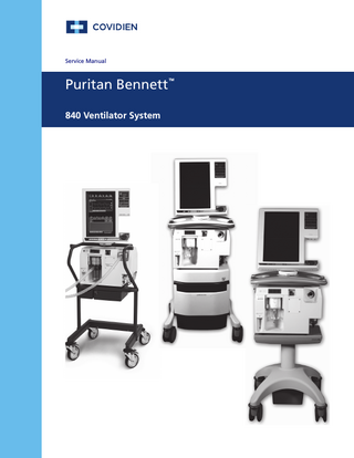
1.2 General product description The Puritan Bennett 840 Ventilator System is a critical care ventilator intended for acute and subacute care of infant, pediatric, and adult patients. Electronically controlled and pneumatically powered, the Puritan Bennett 840 Ventilator System contains a breath delivery unit (BDU), graphical user interface (GUI), and backup power source (BPS). An optional compressor unit and three different cart styles [the RTA (ready-to-assemble) cart, Compressor Mount Cart, and the Pole Cart] are also available. The Compressor Mount Cart, which allows use with an 806 compressor, can be used with a one-hour battery or an optional four-hour battery installed in its BPS, which is located in the BDU shelf. The Pole Cart can also be used with a one-hour battery or an optional four-hour