LABORIE
Urocap III Service Manual Ver 12 July 2014
Service Manual
23 Pages
Preview
Page 1
LABORIE
™
UROCAP III Service Manual Document Number: UC3-SM01 Version Number: 12 Release Date: July 28, 2014 Issued by: R.A. LABORIE OFFICES: USA 400 Avenue D, Suite 10 Williston, Vermont, USA 05495 Sales/Marketing: 802.857.1300 Customer Service: 800.522.6743 Technical Support: 800.333.1039 Fax: 802.878.1122 [email protected]
CANADA 2101 Boul. Lapinière Brossard, Québec, Canada J4W 1L7 Montreal: 450.671.5901 Customer Service: 888.522.6743 Technical Support: 800.333.1039 Fax: 450.671.7182 [email protected]
LABORIE MEDICAL TECHNOLOGIES EUROPE LIMITED Lumonics House, Valley Drive Rugby, Warwickshire CV21 1TQ UK Tel.: +44.01788.547888 Fax: +44.01788.536434 [email protected]
INTERNATIONAL 6415 Northwest Dr., Unit 10 Mississauga, Ontario, Canada L4V 1X1 Customer Service: 905.612.1170 Fax: 905.612.9731 [email protected]
www.laborie.com
UROCAP III is a trademark of Laborie Medical Technologies Canada ULC. Bluetooth is a registered trademark of Bluetooth SIG, Inc. Other names may be trademarks of their respective owners. © Copyright 2014 by LABORIE All rights reserved. No part of this publication may be reproduced in any form whatsoever without the prior written permission of LABORIE. LABORIE MEDICAL TECHNOLOGIES CANADA ULC 6415 Northwest Drive, Unit 10 Mississauga, ON L4V 1X1 CANADA
Table of Contents 1 2
Introduction ... 1 Technical Description ... 2 2.1 2.2 2.2.1 2.2.2 2.2.3 2.2.4
2.3 2.4 2.5 2.6
3
3.2.1 3.2.2
3.3
4.2.1
4.3 4.4
Calibrating the UROCAP III - Standalone Model ... 6 Calibrating the Urocap III - Wired or Wireless PC Model ... 8 Calibration through the Hyper Terminal ... 8 Calibration through the UDS120 Software ... 9
Tips for Better Calibration ... 10 Cleaning ... 11 Preventive Maintenance ... 11 Check the Flow and Volume of the Uroflowmeter ... 11
Virus Protection (for wired/wireless PC model) ... 12 Treating and Disposing of Products After Use ... 12
Troubleshooting... 13 5.1 5.2 5.3
6
Software Features List ... 4 Classifications ... 4 Applicable Directives and Standards ... 4 Accessory Descriptions ... 5
Cleaning and Preventive Maintenance... 11 4.1 4.2
5
Standard Equipment for Standalone Model ... 3 Standard Equipment for Wired to PC Model ... 3 Standard Equipment for Wireless PC Model ... 3 Optional Accessories ... 4
Transducer Calibration ... 6 3.1 3.2
4
System Specifications ... 2 Equipment/Accessory Part Numbers ... 3
Troubleshooting For all models ... 13 Troubleshooting for the UROCAP III standalone model ... 14 Troubleshooting for the UROCAP III wired/wireless PC models ... 15
Electromagnetic Compatibility (EMC) ... 17 6.1 6.2
Emissions ... 17 Immunity ... 17
7
Symbols... 18
8
Schematic – PROPRIETARY INFORMATION ... 19
9
End-User Software License Agreement ... 20
UROCAP III™ Service Manual
LABORIE
1 INTRODUCTION The UROCAP III™ is one of the world’s most compact Uroflowmetry analyzers with built-in comparative studies. These studies, along with other unique features, will deliver highly accurate Uroflowmetry recordings that are easy to produce and interpret. The purpose of this manual is to provide enough information for service and troubleshooting. All service and repair should be done by Laborie trained technicians. For further information or technical service, contact your local sales representative or LABORIE. There are three different UROCAP III models:
the UROCAP III standalone model the UROCAP III wired to PC model the UROCAP III wireless with PC model
The information located in this manual is intended for the Biomedical Department of a hospital or clinic.
Page 1
UROCAP III™ Service Manual
LABORIE
2 TECHNICAL DESCRIPTION 2.1 SYSTEM SPECIFICATIONS Model UROCAP III Dimensions (WxDxH) 15.5cm x 15cm x 11.9cm (6.1" x 5.9" x 4.7") Weight 725 g (1.6 lb) Measurement Ranges and Flow: 0 to 50 ml/s Volume: 0 to 1000 ml Tolerances Channels 2 (Volume and Flow) Sampling Rate 4 points per second per channel Output Thermal Printer of PC software via RS232 (Standalone Model) Desktop Printer (PC Models) Maximum Overload 23 Kg (50 lbs.) Resolution Printer: 140 pixels per channel PC: 8 bits for 1000ml Maximum Study Length 10 min Transportation and Storage Temperature: -20°C to 60°C (-4°F to 140°F) Conditions Humidity: 20% to 80%, non-condensing Pressure: 800hPa to 1014hPa Operating Conditions Temperature: 15°C to 30°C (59°F to 86°F) Humidity: 30% to 75%, non-condensing Pressure: 800hPa to 1014hPa
Page 2
UROCAP III™ Service Manual
LABORIE
2.2 EQUIPMENT/ACCESSORY PART NUMBERS 2.2.1 Standard Equipment for Standalone Model
ITEM UROCAP III, wired Beaker Thermal Printer (modified) Thermal Printing Paper Printer Cable Power Supply Medical Grade Power Cord Commode Chair Uroflow Funnel Plus instruction manuals
PART NUMBER TRA709 DIS173 PRI527 DIS155 CAB432 POW810/POW725 POW005 (110V) or POW740 (220V) CHA171 CHA172
2.2.2 Standard Equipment for Wired to PC Model
ITEM UROCAP III, wired RS-232 Cable Beaker Power Supply Medical Grade Power Cord Commode Chair Uroflow Funnel UROCAP III Software CD Software Key for Urocap software Plus instruction manuals
PART NUMBER TRA709 CAB347 DIS173 POW810/POW725 POW005 (110V) or POW740 (220V) CHA171 CHA172 LAB918 COM397
2.2.3 Standard Equipment for Wireless PC Model
ITEM UROCAP III, wireless Beaker Bluetooth USB Adaptor/ PCMCIA Card Power Supply Medical Grade Power Cord Commode Chair Uroflow Funnel UROCAP III Software CD Software Key for Urocap software Plus instruction manuals
PART NUMBER TRA710 DIS173 COM090/COM094 POW810/POW725 POW005 (110V) or POW740 (220V) CHA171 CHA172 LAB918 COM397
Page 3
UROCAP III™ Service Manual
LABORIE
2.2.4 Optional Accessories ITEM Flow stand Funnel for Uroflow Stand Funnel for folding commode chair Folding Commode Chair HP995C Printer Bluetooth support
PART NUMBER STA700 CHA172 CHA874 CHA180 PRI085/PRI120
2.3 SOFTWARE FEATURES LIST Feature
Item Number FEA125 FEA665 FEA185 FEA395 FEA693 FEA215 FEA150 FEA145
Batch Print Move Events by Drag and Drop Cursor Playback VBN – Normal Curve Overlay Change Channel Order Change Channel Titles and Units Change Channel Scales
2.4 CLASSIFICATIONS Type of protection against electric shock Degree of protection against electric shock Degree of protection against ingress of water Mode of Operation
Class 1 Equipment Type B Equipment IPX1 Equipment Continuous
2.5 APPLICABLE DIRECTIVES AND STANDARDS Directive: MDD Directive 93/42/EEC Standards: IEC/EN 60601-1 IEC/EN 60601-1-2
General Requirements for Safety EMC – Requirements and Tests
UPON REQUEST, LABORIE will make available to the customer any circuit diagrams, component part lists, and/or other technical documentation directly related to the UROCAP III.
Page 4
UROCAP III™ Service Manual
LABORIE
2.6 Accessory Descriptions UROCAP III Transducer The UROCAP III uses a weight transducer to measure both volume and flow rate. A beaker is placed on top of the transducer. When urine is collected in the beaker, the transducer detects the change in weight and the Uroflow procedure starts. Beaker The type of plastic beaker included with the package is the only recommended beaker to be used with the UROCAP III. Using another type of beaker can result in invalid/incorrect Uroflow data. The beaker should be placed on top of the Uroflow transducer in such a way that it is properly seated on the transducer’s dish. Thermal Printer The thermal printer provides the Uroflow study. Thermal Printing Paper The printer must use thermal printing paper for operation. Contact your local authorized dealer or sales representative for replacement rolls. Note: As the paper is running out, a red die line appears. This is an indication to replace the current roll. Power Supply The power supply provides power to both the transducer and the printer. For medical safety it is the only supply to be used for this device. The supply is an auto switcher, which means it can accept the wide range of inputs supplied from all countries. Medical Grade Power Cord To conform to medical standards, the power cord is of a medical grade accepted by hospitals. The plug portion of the cord will vary depending on which country the unit was delivered to or on the customer’s request. A green dot on the plug indicates it conforms to medical standards. Flow stand and Funnel The flow stand allows flexibility for users who have a different commode chair with no funnel. It can also be used for male studies with the man voiding in a standing position. Commode Chair and Funnel The commode chair and funnel are both made of sturdy PVC material. Software Package and Software Key The software package contains the UDS software CD-ROM that is to be installed on a PC computer. The software key sets your software version. Page 5
UROCAP III™ Service Manual
LABORIE
3 TRANSDUCER CALIBRATION The UROCAP III uses software to calibrate the Uroflow transducer. There is no need to open the unit in order to calibrate the transducer. For the UROCAP III with a thermal printer, the instructions will be printed on the paper. For the UROCAP III model with a PC, a software session must be started by going to the Start Menu of Windows and selecting Programs > Laborie > UDS120.
IMPORTANT! Your UROCAP III unit is initially calibrated at the factory before shipment. When you first receive your unit there should be no need to calibrate it. LABORIE recommends that the unit’s calibration be verified at least every six months after its initial calibration. Follow the procedures in this section only if the unit’s calibration is inaccurate.
3.1 CALIBRATING THE UROCAP III - STANDALONE MODEL (The bold print represents what is printed on the paper.) 1. Pre-measure 500 ml of water and place aside. 2. Press and hold the Reprint button for 5 seconds. 3. Release the Reprint button. Result: UROCAP III Transducer Calibration Serial Number: xyxxx Put empty beaker on transducer Press REPRINT button to continue… 4. Place an empty beaker on the Uroflow transducer. Press and release the Reprint button. Result: Please wait… (after 5 seconds) Volume ADC = X1 Flow ADC = X2 Pour 500ml into beaker slowly Press REPRINT button to continue… 5. Slowly pour the pre-measured 500ml of water into the beaker on the Uroflow transducer. Keep a constant flow as much as possible.
Page 6
UROCAP III™ Service Manual
LABORIE
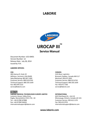
6. When you are finished pouring, press and release the Reprint button. Result: Volume ADC = X3 DeltaFlow50 ADC =X4 Please Remove Beaker. Press REPRINT button to continue… 7. Remove the beaker from the Uroflow transducer. 8. Press and release the Reprint button. Result: Volume ADC = X5 Calibration Completed. Date: ________________ LED blinks red slowly. 9. Tear off the calibration printout. 10. Fill in the calibration date and file it with your calibration records.
Figure 3.1: Sample Calibration Printout NOTE: The values in the sample calibration printout shown here are examples only. Your printout will display different values.
Page 7
UROCAP III™ Service Manual
LABORIE
3.2
Calibrating the Urocap III - Wired or Wireless PC Model
The Urocap III wired or wireless model can be calibrated with a terminal program or through the ServerX menu in the UDS120 software. 3.2.1 Calibration through the Hyper Terminal 1. Start the Urocap III and the PC. NOTE: For the Urocap III wireless with PC model, use the Bluetooth Manager to connect the PC to the Urocap III transducer through a virtual COM port. 2. Double-click the Urocap Calibration icon on the desktop. Result: A terminal program will open.
IMPORTANT! The terminal program is pre-set to use COM2 for Urocap III. If the Urocap III is connected to a different COM port, click Call > Disconnect to disconnect from COM2 and then click File > Properties to change to the correct COM port. To finish, select Call > Call to open the COM port. The status bar shows Connected 0:00:00 with a continuous time increment. 3. Type R (the Reset command) in the terminal program to reset the Urocap III connection. 4. Type UDS-120. (remember to type it exactly as shown here) Result: The letter M will appear. 5. Type C (the Calibration command) to enter calibration mode. Result: Calibration instructions displayed. 6. Follow the instructions to place an empty beaker on the Urocap III transducer and press ENTER. Result: After a brief moment, the Flow and Volume values for no flow and empty beaker are displayed on the terminal program. 7. Follow the instructions to pour 500 ml of water gradually into the empty beaker. Press ENTER when completed. Result: The Flow and Volume values for 50ml/s and 500ml are displayed on the terminal program. 8. Follow the instructions to remove the beaker from the Urocap III transducer and press ENTER. Result: The Volume values for no beaker are displayed on the terminal program followed by the Calibration completed message. 9. Press ENTER. 10. Print the calibration record from the terminal program and keep a copy for your files. 11. Close the terminal program. Page 8
UROCAP III™ Service Manual
LABORIE
3.2.2 Calibration through the UDS120 Software
LABORIE recommends that transducer calibration of the system be verified at least every six months after its latest calibration. Transducer calibration cannot be performed after the selection of a procedure or after opening a file for review. If you make a mistake during calibration do not click Cancel. Continue with the current calibration, and when complete immediately redo the calibration with the correct steps.
Calibration is part of a set used with a particular configuration of catheters and transducers. Start the UDS120 software and click ServerX > Pump/Transducer Calibration to open the Transducer Calibration window OR Click Connection Manager and click the Calibration button next to the UDS device to calibrate to open the Transducer Calibration window.
3.2.2.1 Calibrate Volume 1. Place an empty beaker on the Uroflow transducer. 2. Click on the Common tab name. 3. Select Volume from the transducer list. 4. Type the number zero (0) in the Low Scaled edit box and then click the Apply button. NOTE: For calibration purposes, do not connect a cartridge to the pressure transducer.
5. Place a beaker with 500 ml of water on the Uroflow transducer. *Depending upon the calibration equipment/tools at your disposal, the High Scaled value can also be set to 1000 if you have a correct measure of 1000ml. 6. Input the number 500 (or 1000) in the High Scaled edit box and select the Apply button. Result: Calibration is complete. 7. Select the Flow transducer to calibrate. Page 9
UROCAP III™ Service Manual
LABORIE
3.2.2.2 Calibrate Flow IMPORTANT! Flow can only be calibrated after Volume is calibrated! 1. Select Flow from the transducer list. 2. Place an empty beaker on the Uroflow transducer and select the Apply button. Result: After placing the beaker onto the Uroflowmeter and pressing Apply, the previous screen will be refreshed and new instructions will appear informing you to pour approximately 500ml of water gradually into the beaker. 3. Start pouring the 500 ml of water at a constant rate of 25 – 50 ml/sec into the beaker. DO NOT TOUCH THE SIDES OF THE BEAKER. 4. Calibration is complete.
3.3 TIPS FOR BETTER CALIBRATION
To produce an even flow it is best to use a small hand held funnel. By keeping the water level constant in the funnel as you are pouring, the flow will be relatively constant. If you do not have access to a funnel, a paper or foam cup with a hole in the bottom will suffice.
To verify your calibration, use the same pouring procedure as the calibration, but perform a study. The unit should provide you with the same volume reading as was poured if it was calibrated correctly.
Page 10
UROCAP III™ Service Manual
LABORIE
4 CLEANING AND PREVENTIVE MAINTENANCE 4.1 Cleaning IMPORTANT! Do not soak the Urocap in water or in any other liquids! It is nonimmersible.
Always wear protective gloves when cleaning the transducer to prevent biological contamination. The exterior surface of the transducer and the dish should be wiped using a clean cloth dampened with alcohol, soap, or disinfectant detergent to wipe clean. Immediately wipe the surfaces dry. Do not let any liquid leak into the seams of the transducer. The transducer should be stored in a cool and dry area at room temperature. The Uroflow beaker should be rinsed and dried after use. Soap and water, or a mild detergent solution, can be used for cleaning. NOTE: Although the beaker is reusable, it will discolor over time and may need to be replaced. The chair, flowstand, and funnel can be wiped clean with a cloth dampened with soap or mild detergent and wiped dry immediately.
4.2 Preventive Maintenance Performing regular maintenance will reduce the need for costly repairs. Check the transducer calibration every 6 months or whenever you suspect the transducers are off calibration. If the Uroflowmeter is giving incorrect readings, try the following checkups before attempting to calibrate the system. 4.2.1 Check the Flow and Volume of the Uroflowmeter
4.2.1.1 Check Volume 1. Open the UDS120 software and start a sample Uroflow test. 2. Put an empty beaker on the Uroflow transducer. 3. Select Set Zeroes! 4. Remove the empty beaker. 5. Fill a beaker with 500cc of water and place it on the Uroflowmeter. The volume channel should display a volume of 500ml (+/- 5 ml). If the reading is above or below the 5ml threshold, then calibration is required. See Calibrate Volume in the Calibration chapter in the owner’s manual for information. Once calibration is complete perform a recheck by following steps 1 to 5 listed here. Contact LABORIE service for assistance if problems continue after the calibration and re-check.
4.2.1.2 Check Flow 1. Open the UDS120 software and start a sample Uroflow test. 2. Put an empty beaker on the Uroflow transducer. 3. Select Set Zeroes! Page 11
UROCAP III™ Service Manual
LABORIE
4. Fill another beaker with 500cc of water. 5. Slowly and steadily pour the water from the filled beaker into the empty beaker. Try to keep the rate between 25 to 50 ml/second. The volume channel should display a volume of 500ml (+/- 5 ml). If the reading is above or below the 5ml threshold, then calibration is required. See Calibrate Flow in the Calibration chapter in the owner’s manual for information. Once calibration is complete perform a recheck by following steps 1 to 5 listed here. Contact LABORIE service for assistance if problems continue after the calibration and re-check.
4.3 Virus Protection (for wired/wireless PC model) All computers purchased from LABORIE are virus-free before shipment and are installed with the an Antivirus program. It is the customer’s responsibility to correctly use and maintain the antivirus program to prevent virus problems. LABORIE is not responsible for any virus related computer problems after point of delivery to the customer.
4.4 Treating and Disposing of Products After Use
After use, discard the contaminated, plastic, single-use disposables and any packaging according to your institution’s standard operating procedures on medical waste handling. For end of life product waste electrical and electronic equipment should be collected separately and returned to the designated local recycling service. Packaging waste should be collected separately for available national packaging collection and recycling service.
Page 12
UROCAP III™ Service Manual
LABORIE
5 TROUBLESHOOTING If the system is not working properly, please use the following troubleshooting table to identify the problem. If the problem cannot be resolved by the following methods, please contact LABORIE. DO NOT ATTEMPT TO REPAIR OR SERVICE THE DEVICE YOURSELF.
5.1 TROUBLESHOOTING FOR ALL MODELS SYMPTOM No LED?
POSSIBLE CAUSES Power cord is unplugged?
CHECK/CORRECTIVE ACTION Check power cord.
Uroflow signal does not respond? (LED is red)
Uroflow transducer improperly connected? Transducer inside housing is disconnected?
Reconnect all cables to the UROCAP III.
Uroflow signal shows vibration and/or spike patterns?
Plastic beaker is touching the flow funnel? Patient has touched the transducer with their feet? Floor is unsteady? Internal malfunction?
Reposition the transducer and re-check.
Beaker not properly seated on transducer dish? Funnel is touching beaker? Incorrect beaker in use? UROCAP III is not sufficiently warmed up?
Adjust beaker position.
Model-specific troubleshooting? Transducer has been damaged by electrical shock? Internal calibration defect?
See following sections in this chapter for model-specific troubleshooting. Contact LABORIE’s Service team.
Incorrect flow or volume readings?
Other Possible Symptoms
Page 13
Contact LABORIE’s Service team.
Ask patient to remain calm during procedure. Move to a more solid foundation. Contact LABORIE’s Service team.
Adjust commode chair or UROCAP III transducer. Use beakers supplied by Laborie ONLY. Allow 2 minutes for transducer to warm up.
Contact LABORIE’s Service team.
UROCAP III™ Service Manual
LABORIE
5.2 TROUBLESHOOTING FOR THE UROCAP III STANDALONE MODEL SYMPTOM No power on printer?
No printout? (Blank page)
Printout from thermal printer is faded?
POSSIBLE CAUSES Power cord is unplugged?
CHECK/CORRECTIVE ACTION Check power cord.
Power switch not turned on? Internal malfunction? (UROCAP III LED solid Red)
Check power switch.
Incompatible type of paper? Printing on wrong side of paper? LED on housing is solid Red?
Use paper supplied by Laborie only.
Build-up of residue (ink or dust) on printer roller?
Paper jam?
Page 14
Contact LABORIE’s Service team.
Turn paper over. Wait for the LED to turn Green before starting a test. 1. Lift off printer cover. Refer to the thermal printer owner’s manual for instructions on removal. 2. Clean the thermal print head with an alcohol wipe and let dry. 3. Place the printer cover securely back into place. 1. Lift off printer cover. Refer to the thermal printer owner’s manual for instructions on removal. 2. Remove any pieces of paper that may be caught in the printing mechanism. 3. Place the printer cover securely back into place.
UROCAP III™ Service Manual
LABORIE
5.3 TROUBLESHOOTING FOR THE UROCAP III WIRED/WIRELESS PC MODELS SYMPTOMS Cannot establish connection?
POSSIBLE CAUSES Wrong (Virtual) COM port in use? Incorrect Communication parameters?
CHECK/CORRECTIVE ACTION Check COM port settings.
Connection broken?
Cable not connected properly? (Wired PC model only) Weak Bluetooth signal and/or transducer used in a noisy environment? (Wireless PC model only)
Make sure cable is connected properly between PC and Urocap III wired transducer Move the Urocap III and PC away from other electronic devices in use. Re-position the PC or Urocap III so that there is no barrier (open air) between them. Move the computer and Urocap III closer together. [The maximum distance allowed between the Urocap III and the computer is 10 meters (33 feet)]
Error message: “Error Code: 66a (Can't install KB2160841)” appears?
.NET Framework file needs repair
Make sure communication parameters are 19200 baud, 8 data bits 1 stop bit, no parity, no flow control. Wrong cable or cable not Make sure the correct cable is used, and connected properly? connect it properly between the PC and (Wired PC model only) the Urocap III transducer. No Bluetooth connection? Check if Bluetooth driver is set up (Wireless PC model only) properly. Check if Bluetooth device is plugged in properly. Try searching, pairing, and connecting to device again.
Page 15
Click Start > Control Panel and double-click Add or Remove Programs – OR- Click Start > Control Panel > Programs > Programs and Features. In the resulting list, right-click the Microsoft .NET Framework 4 Client Profile file and select Change OR select Uninstall/Change Select to Repair the file and wait for the repair to complete before continuing.
UROCAP III™ Service Manual
LABORIE
SYMPTOMS UDS report not transferring to iLIST Office Reporter?
POSSIBLE CAUSES Make sure i-LIST MsgQListener is running.
Install Windows Updates
Repair .NET Framework File
CHECK/CORRECTIVE ACTION Close all open programs. Make sure iLIST Message Queue Listener is running by clicking Start > Programs > Laborie > i-LIST MsgQListener. Restart the computer and attempt to send a report to i-LIST Office Reporter. If unsuccessful try the solution below. Close all open programs. Click Start > Control Panel and double-click Windows Updates -ORClick Start > All Programs > Windows Updates. If there are updates waiting for installation, install them and then restart the computer. Once restarted, attempt to send a report to i-LIST Office Reporter. If unsuccessful try the solution below. Click Start > Control Panel > and double-click Add or Remove Programs. –OR- Click Start > Control Panel > Programs > Programs and Features. In the resulting list, right-click the Microsoft .NET Framework 4 Client Profile file and select Change OR select Uninstall/Change Select to Repair the file and wait for the repair to complete. Restart the computer and continue with sending a UDS report to iLIST Office Reporter.
If problems continue, please contact LABORIE’s Service team at 1-800-333-1039 or email [email protected].
Page 16
UROCAP III™ Service Manual
LABORIE
6 ELECTROMAGNETIC COMPATIBILITY (EMC) Standard(s) to which Conformity is Declared: EN 60601-1-2:2001
Medical Electrical Equipment--Part 1-2: General Requirements for Safety-2.Collateral Standard: Electromagnetic Compatibility--Requirements and Tests
6.1 EMISSIONS Standard
Description
CISPR 11:2003, +A1: 2004, Group 1, Class A
Industrial, Scientific and Medical (ISM) Radio-Frequency Equipment -Electromagnetic Disturbance Characteristics - Limits and Methods of Measurement
6.2 IMMUNITY Standard
Description
Severity Applied
Compliance Criteria
EN 61000-4-2:1995, +A1: 1998, +A2: 2001
Electrostatic Discharge
8kV air; 6kV contact
Cl. 36.202.1.j
EN 61000-4-3:1996, +A1: 2002
Radiated RF Immunity
3V/m, 80-2500MHz, 80% AM Modulation with a 1.0 kHz sine wave
Cl. 36.202.1.j
EN 61000-4-4: 2004
Electrical Fast Transients
±1kV (5kHz) input/output lines ±2kV (5kHz) power supply lines
Cl. 36.202.1.j
EN 61000-4-6:1996, +A1: 2001
Conducted RF Immunity
3V/m, 0.15-80 MHz, 80% AM modulation with a 1kHz sine wave
Cl. 36.202.1.j
EN 61000-4-11:2004
Voltage Dips and Short Interruptions
Dips: 95% reduction for 0.5 cycle, 60% for 5 cycles, 30%reduction for 25 cycles; interruption > 95% for 5 sec.
Cl. 36.202.1.j
This device complies with Part 15 of the FCC Rules. Operation is subject to the following two conditions: (1) this device may not cause harmful interference, and (2) this device must accept any interference received, including interference that may cause undesired operation. This device contains: FCC ID: PVH0939 IC: 5325A-0939
Page 17