Service Manual
18 Pages
Preview
Page 1
The LiftCare Bed Company Victorian Head Office, Showroom & Service Centre Unit 9, 271 Wells Road, Chelsea Heights, 3196, Australia Office: +61 3 8773 1111 Fax: +61 3 9773 4008 Unit 119, 7 Hoyle Avenue, Castle Hill, 2154 Tele/Fax: +61 2 8850 5981
5
Sales & Service Hotline : 1300 132 736 (Australia Only) Email: [email protected] www.liftcarebeds.com
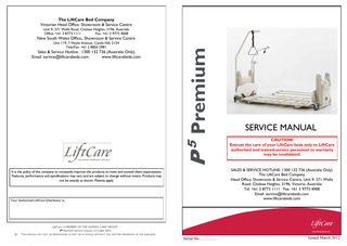
P Premium
New South Wales Office,, Showroom & Service Centre
Your Authorised LiftCare Distributor is:
LiftCare. A MEMBER OF THE HUMAN CARE GROUP. P5 PREMIUM SERVICE MANUAL OCTOBER 2010 THIS MANUAL MAY NOT BE REPRODUCED IN PART OR IN WHOLE WITHOUT THE WRITTEN PERMISSION OF THE PUBLISHER.
CAUTION! Entrust the care of your LiftCare beds only to LiftCare authorised and trained service personnel or warranty may be invalidated.
SALES & SERVICE HOTLINE: 1300 132 736 (Australia Only) The LiftCare Bed Company Head Office, Showroom & Service Centre, Unit 9, 271 Wells Road, Chelsea Heights, 3196, Victoria, Australia Tel: +61 3 8773 1111 Fax: +61 3 9773 4008 Email: [email protected] www.liftcarebeds.com
It is the policy of the company to constantly improve the products to meet and exceed client expectations. Features, performance and specifications may vary and are subject to change without notice. Products may not be exactly as shown. Patents apply.
36
SERVICE MANUAL
LiftCare. A MEMBER OF THE HUMAN CARE GROUP. P5 PREMIUM SERVICE MANUAL OCTOBER 2010 THIS MANUAL MAY NOT BE REPRODUCED IN PART OR IN WHOLE WITHOUT THE WRITTEN PERMISSION OF THE PUBLISHER.
Serial No………….
1
Issued March 2012
NOTES CONTENTS Intended use of bed ····································································· 4 Maintenance·············································································· 5 Maintenance Checklist (Safety Audit) ················································ 6 Replacement of Electrical Components ············································· 8 Replacement Parts (Obtaining)························································ 8 How to change/repair Chains ························································· 9 How to remove covers ································································ 9 How to remove/change Control Box ··············································· 11 How to change Handset ······························································ 11 How to change Battery Backup ······················································ 11 How to remove/replace Actuators·············································· 10-11 How to remove/ replace Accessories Push Handle ··································································· 12 Self Help Pole ································································· 12 IV Pole ·········································································· 12 Side Rails ······································································· 13 Extension Kits ····························································· 14-15 Parts List…………………………………………………………...18-30
WARNING! Service work contained in this manual should only be undertaken by LiftCare trained and authorised service agents. Only LiftCare supplied parts should be used. Failure to comply with the above two items will void warranty and could result in further unnecessary damage to the bed and possible extreme safety hazard to the person occupying the bed and/or caring staff. PURPOSE
This document will be made available to LiftCare staff, distributors, agents and authorised LiftCare service providers. It is not for publication or distribution to the public or clients who may use the information to allow companies or individuals to repair or modify LiftCare products. This document and its contents are intended to be used in the performance of service on LiftCare produced products, i.e. Protean range series products. This document also serves as a reference for office and sales staff in the performance of their duties, i.e. collecting service call information to facilitate the expedient diagnosis of any problems and problem solutions. This document should be read in conjunction with LiftCare’s Operating and Assembly Guides, Instruction Manuals and Spare Parts Catalogues. This document is copyright to LiftCare Beds and must not be reproduced in any form without the written permission of LiftCare. LiftCare. A MEMBER OF THE HUMAN CARE GROUP. P5 PREMIUM SERVICE MANUAL OCTOBER 2010 2
THIS MANUAL MAY NOT BE REPRODUCED IN PART OR IN WHOLE WITHOUT THE WRITTEN PERMISSION OF THE PUBLISHER.
LiftCare. A MEMBER OF THE HUMAN CARE GROUP. P5 PREMIUM SERVICE MANUAL OCTOBER 2010 THIS MANUAL MAY NOT BE REPRODUCED IN PART OR IN WHOLE WITHOUT THE WRITTEN PERMISSION OF THE PUBLISHER.
35
PARTS LIST Part Number
Qty / bed
Push handle. P3 push handle ass'y
HD008
1
Handle mount bracket - Right hand
HD001
1
Right hand mount bracket
HD001-1
1
M8 x 46.5 long stud
HD009
1
Stop button Handle mount bracket - Left hand
HD011 HD001
1 1
Left hand mount bracket
HD001-2
1
M8 x 46.5 long stud
HD009
1
Stop button
HD011
1
Lock bracket - Right hand
HD002
1
M8 x 40.5 long stud
HD010
1
6.0mm pin lock plunger
SL000
1
Plunger M6
SL02
1
Body 6.0mm plunger
SL01
1
Compression spring - 9x30x1.0
SL06
1
Lock knob
HD012
1
per description
1
Lock bracket - Left hand
HD002
1
M8 x 40.5 long stud
HD010
1
6.0mm pin lock plunger
SL000
1
Plunger M6
SL02
1
Body 6.0mm plunger
SL01
1
Compression spring - 9x30x1.0
SL06
1
Lock knob
HD012
1
per description
1
Handle cover plate
HD004
2
Push handle
HD005
1
Part Description
M3 x 3 Phillips Head Screw
M3 x 3 Phillips Head Screw
LiftCare. A MEMBER OF THE HUMAN CARE GROUP. P5 PREMIUM SERVICE MANUAL OCTOBER 2010 34
THIS MANUAL MAY NOT BE REPRODUCED IN PART OR IN WHOLE WITHOUT THE WRITTEN PERMISSION OF THE PUBLISHER.
APPLIED STANDARDS
P5 Premium Floor Level Folding Electric Bed
with its mechanical and electrical adjustment devices complies with the regulations of the EC Directive 93/42/EEC for Medical Products This bed is categorised as a Class 1 Medical Product. Applied Harmonized Standards AS/NZS 3200.2.38.2007 Medical Electrical Equipment-particular requirements for safety-Electrically and manually operated medical beds for adult use (IEC 60601-2-38, Ed.1.0(1996) MOD) EN60601-2-38:1998 Medical Electrical Equipment-Part 2 Particular Requirements for the Safety of Electrically Operated Hospital Beds.
~Warranty~ This LiftCare Bed is warranted against component and manufacturing defects for a period of 10 years on the steel frame and 3 years on most other parts other than battery, provided the bed is assembled, operated and maintained in accordance with these instructions. It excludes fair wear and tear and normal maintenance requirements, such as replacement of batteries, accidental breakages, or claims due to physical or operational mishandling. This warranty covers parts and labour on the bed structure and standard LiftCare accessories only. Consequential and other costs such as transportation to and from the repair base are not covered. Any service or other work, or interference with the bed, its components or operations, other than that by currently authorised LiftCare service personnel, may invalidate this Warranty LiftCare is committed to a continuous improvement policy and reserves the right to change specifications without notice. All measurements are approximate. E&OE.
LiftCare. A MEMBER OF THE HUMAN CARE GROUP. P5 PREMIUM SERVICE MANUAL OCTOBER 2010 THIS MANUAL MAY NOT BE REPRODUCED IN PART OR IN WHOLE WITHOUT THE WRITTEN PERMISSION OF THE PUBLISHER.
3
PREFACE
PARTS LIST
Read and understand this manual before attempting to service or repair the equipment. This manual must be kept in an easily assessable are for future reference. Warnings, Cautions and Notes All warnings, cautions and notes must be strictly adhered to. Failure to comply with this guide may result in harm to patient or caregiver. WARNINGS given in this manual identify possible hazards in procedures or conditions which, if not correctly followed, could result in death, injury or other serious adverse reactions. Cautions given in this manual identify procedures or conditions which, if not correctly followed, could result in equipment failure or damage. Notes given in the manual are used to explain or amplify a procedure or condition.
Part Number
Qty / bed
Lower beams. Lower beam assembly
ZZ613
1
Lower beam
ZZ691
4
Platform beam end plug
ZZ168
4
Lower Saddle Assembly
ZZ650
1
Bottom hinge saddle assy
ZZ640
2
Self Clinching Nut
CM8-1
8
Cross beam
ZZ139
1
Outer cross rail
ZZ260
2
Connector plate
ZZ623
4
Button head cap screw - M8 x 45mm
per description
16
Nyloc nut - M8
per description
16
ABS lower cover securing bracket
ZZ240
4
Lower cover self tapping screws
per description
4
Pop rivets for lower cover brackets
per description
12
ZZ1751
2
Snap latch screw - M8 x 45mm BHCS
per description
2
Snap latch nut - M8 nyloc
per description
2
Headed pin 10x8x42
10x8x42HP
4
Circlip to suit headed pin
per description
4
Button head cap screw - M8 x 45mm
per description
16
Nyloc nut - M8
per description
12
Part Description
Snap latch
LiftCare. A MEMBER OF THE HUMAN CARE GROUP. P5 PREMIUM SERVICE MANUAL OCTOBER 2010 4
THIS MANUAL MAY NOT BE REPRODUCED IN PART OR IN WHOLE WITHOUT THE WRITTEN PERMISSION OF THE PUBLISHER.
LiftCare. A MEMBER OF THE HUMAN CARE GROUP. P5 PREMIUM SERVICE MANUAL OCTOBER 2010 THIS MANUAL MAY NOT BE REPRODUCED IN PART OR IN WHOLE WITHOUT THE WRITTEN PERMISSION OF THE PUBLISHER.
33
PRODUCT DESCRIPTION
PARTS LIST
Part Number per description
Qty / bed 4
Sprocket axle holder inner
ZZ1500
4
Clinch nuts - M5
CM5-2
8
Shore lube bush to suit sprocket holders
per description
4
Leg cap screws - M5 button head x 8mm
per description
16
ZZ1499
4
Part Description Shore lube bush to suit sprocket holders
Sprocket assembly Sprocket shaft
ZZ1501 3/8 x 25 tooth plate sprocket
Sprocket Sprocket Retainer
Electrically actuated Trendelenberg (and reverse) tilt with horizontal pause feature.
4
Electrically actuated knee break and back rest.
ZZ1502
4
per description
4
Actuator top mount bracket
ZZ1515
2
Actuator Top Bar
ZZ1507
2
Curved Leg Cross Member
ZZ1510
4
per description
2
Bracket
ZZ1508
2
Lift support bracket
ZZ1600
2
ACK mounting plate Self clinching studs ( to suit ACK mounting plate M5 x 8)
per description
1
per description
4
Nyloc nut - M5
per description
4
Self clinching studs (to suit PCB - M4 x 5)
per description
4
Nyloc nut - M4
per description
4
Actuator anti rotation bracket
ZZ1680
2
Extrusion retainer
ZZ1530
4
per description
16
ZZ1750
2
per description
2
P5 CB06 Bracket
P5548
1
P5 Battery bracket
P5549
1
Retainer screw - self tapping Snap latch anchor Snap latch anchor screw - BHCS 8mm x 15
LiftCare. A MEMBER OF THE HUMAN CARE GROUP. P5 PREMIUM SERVICE MANUAL OCTOBER 2010 32
The following features are included on the P5 Premium bed: Four section, electrically operated profiling mattress platform with independent adjustment of platform sections via either the attendant control panel at the foot end of the bed or by the hand control unit.
4
Simplex chain & con links
Actuator top fixing C/sunk screw M8 x 20
The LiftCare P5 Premium Floor Level Bed is an electrically–actuated floor level bed with multiple functions to provide the best nursing position for both patient and caregiver.
THIS MANUAL MAY NOT BE REPRODUCED IN PART OR IN WHOLE WITHOUT THE WRITTEN PERMISSION OF THE PUBLISHER.
Removable head and foot boards. Battery back up for all powered functions. Dual sided CPR levers for emergency release of backrest. Attendant control panel with locking functions. Auto CPR function. Handset with Lock Out features.
LiftCare. A MEMBER OF THE HUMAN CARE GROUP. P5 PREMIUM SERVICE MANUAL OCTOBER 2010 THIS MANUAL MAY NOT BE REPRODUCED IN PART OR IN WHOLE WITHOUT THE WRITTEN PERMISSION OF THE PUBLISHER.
5
INTENDED USE OF THE BED This bed is designed for use in hospitals, aged care, community care and private homes for the purposes of providing comfort and care for any adult person being ill, frail, disabled or in need of care.
PARTS LIST Part Description
Part Number
Qty / bed
M10 lock nut plate
LCB-001-024
8
The Safe Working Load (SWL) of this bed is 250kg/550lbs/39 stone. Due allowance must be made for the mattress, bedding, accessories or visitors or carers sitting or putting extra weight on the bed, when considering normal maximum patient weight.
Button head cap screw - M10 x 45mm
per description
8
Chain anchor
LCB-001-012-05
4
Rolled pins M5 x 40.0mm long
per description
8
It is not recommended to use this bed for patients over 200kg/440lbs/31 stone for which LiftCare has other suitable beds with up to 455kgs/1000lbs/71 stone Safe Working Load.
Slider plate pivot L/H
PR0017-1
1
IV pole bracket
PR0020
1
IV pole tube
Welded to PR0020
1
This bed may only be operated by persons who have received instructions in its safe operation. The bed may only be operated under the conditions of duty described in the LiftCare Instruction Manual which is provided with every bed. (Extra copies can be obtained from LiftCare). CAUTION ANY OTHER USE OF THIS BED SHALL BE REGARDED AS NONCOMPLIANT WITH THE REQUIREMENTS AND MAY INVALIDATE WARRANTY.
Slider plate pivot R/H
PR0017-2
1
IV pole bracket
PR0020
1
IV pole tube
Welded to PR0020
1
Slider plate L/H
PR0016-1
1
IV pole bracket
PR0020
1
IV pole tube
Welded to PR0020
1
Slider plate R/H
PR0016-2
1
Materials in the bed - the bed is built for the most part from steel, the surface of which has been finished with an electro-coated powder-coating. The head and foot end pedestal covers of the bed are ABS plastic. None of the surfaces are harmful to skin contact.
IV pole bracket
PR0020
1
IV pole tube
Welded to PR0020
1
Slider roller dowel pins - M6 x 30mm
per description
8
Slider joint arm growth
LCB-001-018-100
2
Growth link screws - M8 button head x 25mm
per description
2
Growth link washer
per description
2
Growth link nyloc nuts - M8
per description
2
Button head cap screw - M8 x 45mm
per description
2
Nyloc nut - M8
per description
2
Chain retainer
ZZ170 rev1
4
per description
16
ZZ1520
4
Structural Design - the mattress platform is divided into a back rest, split seat section and on some models, a thigh and calf lift section (Kneebreak or Knee Gatch). The mattress base can be horizontally adjusted in height. The bed can be adjusted to a head-low or feet low (Trendelenburg and Reverse or Tilt position). Chassis – the chassis is constructed of welded steel and features four individually locking castors (3 brake-red) and 1 directional lock (usually green). Electrical Adjustment system– the electric adjustment system of this bed comprises: A handset for use by the patient. The handset consists of a robust, easy-care, wash -down plastic casing with membrane keypad. Motors for controlling the adjustment of the backrest and Kneebreak The height of the bed
Chain retainer self tapping screws Sprocket axle holder outer
The central control box unit and battery backup are located underneath the covers LiftCare. A MEMBER OF THE HUMAN CARE GROUP. P5 PREMIUM SERVICE MANUAL OCTOBER 2010 6
THIS MANUAL MAY NOT BE REPRODUCED IN PART OR IN WHOLE WITHOUT THE WRITTEN PERMISSION OF THE PUBLISHER.
LiftCare. A MEMBER OF THE HUMAN CARE GROUP. P5 PREMIUM SERVICE MANUAL OCTOBER 2010 THIS MANUAL MAY NOT BE REPRODUCED IN PART OR IN WHOLE WITHOUT THE WRITTEN PERMISSION OF THE PUBLISHER.
31
MAINTENANCE
PARTS LIST Part Number
Qty / bed
Lower leg assembly
LCB-001-012-0700-SA
2
Castor outrigger L/H
LCB-001-050-2
2
Castor outrigger R/H
LCB-001-050-1
2
Cross beam lower leg assy
LCB-001-012-04
2
LCB-001-012-700-1
4
ZZ1518
2
Headed pin - 12x10x50 (Actuator mount)
12x10x50HDP
2
Circlip to suit headed pin
per description
2
Dual wheel castor spacer
ZZ338
4
Castor dome nuts M12
4
Directional castor marker
per description OD-38mm, ID-12.5mm, 1.5mm thick
Lower beam connector L/H
ZZ1541
2
Lower beam connector plate
ZZ1540
2
Lower beam coach bolt M12 x 25mm
per description
4
M12 nyloc nut for coach bolt
per description
4
Lower beam connector R/H
ZZ1542
2
Lower beam connector plate
ZZ1540
2
Lower beam coach bolt M12 x 25mm
per description
4
M12 nyloc nut for coach bolt
per description
4
Part Description Pedestal Ends.
700 Leg Actuator mount bracket bottom
1
at the head end of the bed. Here a transformer provides a safe low voltage of 24v which is non-harmful for both the patient and user. Connected to the central control unit, via dust and moisture proof plugs, are all the electric motors and the handset which work on a safe low voltage of 24v. Battery backup allows for off-mains power emergency operation (for a limited period of time). Operators of hospital beds are obligated to keep medical products in a safe state throughout their entire service life. This also includes regularly carrying out expert, LiftCare authorised maintenance and safety checks. As a result of improper operation as well as long-time use, damage, defects, and signs of wear may occur. Such defects can present hazards if not promptly recognised and eliminated. CAUTION If damage or a malfunction is suspected, the bed must be withdrawn from service immediately until repairs have been carried out or the defective parts have been replaced. LiftCare suggests regular inspections by users (See checklist page 6) As a guideline, it is recommended that an annual inspection be carried out on all LiftCare Beds. The protocol template for inspections is found on the following pages. Contact LiftCare for information on the Safety and Condition Audit program Maintenance Checklist – Explanatory Notes VISUAL CHECKS Handset Cable – Check for cracks in plastic insulation, check for breaks in casing, cable holder and plugs.
Mains Cable – as above Handset – Check that all functions work and ensure there is no damage. Chassis – Check the bed frame for bent or corroded pieces; ensure that all bolts and screws are tight.
Head & Foot Covers/boards/caps – Check ABS covers have no cracks and are secured tightly, head and Foot boards are in place and ABS caps have no cracks and are secure. Castors – Check that each wheel will turn, test the brake and directional locking. Ensure that each castor is tightly secured.
Paintwork/Corrosion – Ensure all metal parts have no flaking paint or signs of rust. Bed Extension (If Fitted) – Check this has been installed correctly and all bolts are tight. Accessories correctly fitted – Check that all accessories fitted to the bed have been correctly installed and that all the bolts are tight.
Serial No. Label – Each bed has its own Serial Number and the label is found on the rail running underneath the mattress platform. Check that this in place. LiftCare. A MEMBER OF THE HUMAN CARE GROUP. P5 PREMIUM SERVICE MANUAL OCTOBER 2010 30
THIS MANUAL MAY NOT BE REPRODUCED IN PART OR IN WHOLE WITHOUT THE WRITTEN PERMISSION OF THE PUBLISHER.
LiftCare. A MEMBER OF THE HUMAN CARE GROUP. P5 PREMIUM SERVICE MANUAL OCTOBER 2010 THIS MANUAL MAY NOT BE REPRODUCED IN PART OR IN WHOLE WITHOUT THE WRITTEN PERMISSION OF THE PUBLISHER.
7
MECHANICAL CHECKLIST/CHECKS TO PERFORM Checked
OK
NOT OK
PARTS LIST Description of fault
Part Description
Visual check of the electrical components Handset cable
Damage, routing
Mains cable
Damage, routing
Handset
Damage, membrane
Part Number
Qty / bed
Nyloc nut - M6
Visual check of the mechanical components
4
Hinge assy - Small - F3 to ZH003 (Middle) Hinge support - Male
ZZ150 ZZ149
2 2
Hinge pin
ZZ128
2
Hinge support - Female
ZZ131
2
Mattress Platform is parallel to floor (ie level)
Damage
Button head cap screw M6
per description
8
Chassis
Damage, deformations
Nyloc nut - M6
per description
8
Mattress Platform, covers
Damage
Hinge assy - Small - F3 to F4 (Foot end)
ZZ133
2
Check for rust or corrosion.
Damage
Hinge support - Male
ZZ133
2
Castors
Damage
Hinge pin
ZZ128
2
Bed Extension
Damage
Hinge support - Female
ZZ131
2
Performance check of the electrical components
Button head cap screw M6
per description
8
Backrest
Adjustment, secure retention
Nyloc nut - M6
per description
8
Kneebreak
Adjustment, secure retention
Platform beam
ZH003
4
Platform beam end plugs
ZZ168
4
Connection pivot LH
ZZ081
2
Connection pivot RH
ZZ082
2
Platform Hi/Lo
Adjustment, secure retention
Battery Backup
Check fully charged & operational
Leg lock bracket
ZZ189
1
Handset
Adjustment, secure retention
Leg lock nut - M8
per description
2
P5 Crush plate - Head end
P5532
2
Crush plate
ZZ532
2
Nylon bush for slider plate pivot
LCB-001-017-018
4
Slider joint arm growth spacer
LCB-001-018-101
2
Button head cap screw - M8 x 45mm
per description
34
Nyloc nut - M8
per description
34
Earth wire - (Class 1 electrical beds only) Button head cap screw M5 x 5 for earth wire
per description per description
1 2
Accessories (eg: Self Help Pole, side rails)
Fastening, damage
Signature of the Inspector:
Name of Inspector:
Inspection result:
Date:
Note: LiftCare recommends regular user checks.
Kneebreak Maximum up/down – Operate kneebreak to fullest height and check for any damage. Backrest Maximum up/down – Operate backrest to fullest height and check for any damage. Trendelenburg Maximum forward & reverse – Operate Trendelenburg LiftCare. A MEMBER OF THE HUMAN CARE GROUP. P5 PREMIUM SERVICE MANUAL OCTOBER 2010
8
THIS MANUAL MAY NOT BE REPRODUCED IN PART OR IN WHOLE WITHOUT THE WRITTEN PERMISSION OF THE PUBLISHER.
LiftCare. A MEMBER OF THE HUMAN CARE GROUP. P5 PREMIUM SERVICE MANUAL OCTOBER 2010 THIS MANUAL MAY NOT BE REPRODUCED IN PART OR IN WHOLE WITHOUT THE WRITTEN PERMISSION OF THE PUBLISHER.
29
PARTS LIST Part Description
Part Number
Qty / bed
P clip
20-PUC04A
6
Spring clip 9.5mm wide
20-PFC03
8
Spring clip 12.7mm wide
20-PFC08
1
Self tapping screw for clips
per description
15
Lift up actuator support bracket - Knee end assy
ZZ146
1
Support frame
ZZ145
1
Actuator mount plate
ZZ123
2
Headed pin 12x10x50
12x10x50HDP
1
Circlip to suit Headed pin
per description
1
Centre hinge assy - Large
ZH007
2
R/H Hinge assy
ZH005
2
L/H Hinge assy
ZH006
2
Hinge plate
ZH010
8
Other hinge plate
ZH012
8
Hinge shim plate
ZH014
4
Hinge dowel pins - M5 x 25 long
per description
8
Headed pin - 12x10x30
12x10x30HDP
2
Circlip to suit Headed pin
per description
1
Pin with lanyard Self tapping screw for lanyard
per description per description
2 2
Hinge assy - Small - F1 to F7 (Head end)
ZZ129
2
Hinge support - Male
ZZ127
2
Hinge pin
ZZ128
2
Hinge support - Female
ZZ131
2
Button head cap screw M6
per description
8
LiftCare. A MEMBER OF THE HUMAN CARE GROUP. P5 PREMIUM SERVICE MANUAL OCTOBER 2010 28
THIS MANUAL MAY NOT BE REPRODUCED IN PART OR IN WHOLE WITHOUT THE WRITTEN PERMISSION OF THE PUBLISHER.
to fullest height Quiet smooth Hi/Lo Function – Operate bed up and down checking that it is quiet and goes smoothly up and down End covers and fittings – Check all covers are fitted correctly and secured to frame of bed. Castors tight and lockable – check castor fixing bolts are tight, check directional castor (Green tab) x 1 and locking castors x 3 for correct function. Hi-lo drive mechanism – Check raise/lower actuators for excess noise or slow operation. Check nylon bushes for wear or damage. Side Rails – Check condition of side rails and brackets, ensure that the screws are tight.
STRUCTURAL Visible distortion of frame – Check frame for bent or cracked metal parts. Visible serious client damage – Check for damage caused by bed lifters etc. and report to client. Structural Fractures – Check for cracks or tears in steel frame Hinges/mounts not bent – Check all the hinges on platform, actuator fixing points & platform fixing points for damage.
ELECTRICAL Battery backup working/condition – Disconnect mains cable from power point and operate bed. Handset buttons all working - Check all functions on handset Cables secure and in good condition - Check that all cables are secured correctly, not hanging loose. All Actuators secured & working – Check for excessive noise, vibration or cracks in casing.
REPLACEMENT PARTS Note: In order to maintain operational safety and the right to claim under warranty, only original LiftCare replacement parts may be used! Please quote part numbers for each item as per the LiftCare Spare Parts List The corresponding replacement parts can be obtained from the LiftCare
LiftCare. A MEMBER OF THE HUMAN CARE GROUP. P5 PREMIUM SERVICE MANUAL OCTOBER 2010 THIS MANUAL MAY NOT BE REPRODUCED IN PART OR IN WHOLE WITHOUT THE WRITTEN PERMISSION OF THE PUBLISHER.
9
ELECTRICAL COMPONENTS office or distributor When ordering, please specify – TYPE & ITEM as listed in the LiftCare Spare Parts List. REPLACEMENT OF ELECTRICAL COMPONENTS Safety information on replacing electrical components
PARTS LIST Part Number
Qty / bed
CPR Handle Rod part1
CPR513
1
CPR Handle part 2
CPR514
1
Part Description
Nylon washer for handle
per description
1
This is a Class 2 electrical product.
Grub screw for handle - M5 x 5mm
per description
1
WARNING! Before commencing any work on electrical equipment, always unplug the mains cable from the electrical socket.
CPR Handle - RH
CPR519
1
Handle RH CPR
CPR518
1
CPR Handle part 2
CPR514
1
Nylon washer for handle
per description
1
Grub screw for handle - M5 x 5mm
per description
1
CPR Release Rod
CPR515
1
CPR Handle Stop Bracket
CPR545
1
Damper - Gas spring 1500N
4202ZG/K1/D1
1
Shoulder bolt - M8 x 12.0mm long (M6 thread).
per description
1
Nyloc nut - M6
per description
1
M6 flat washer to suit shoulder bolt
per description
1
Nylon washer for Damper lift bracket
per description
1
Cable tie
per description
1
Button head cap screw - M8 x 25mm
per description
2
Nyloc nut - M8
per description
2
Cable tie - 5mm
per description
2
Any work and/or repairs to the electrical equipment may only be carried out by service engineers, qualified technicians or authorised electricians in compliance with all the relevant country of use safety standards. All electrical drive system components (actuators, handset, and control box) are maintenance-free and must not be opened. In the event of a malfunction, the corresponding component must always be replaced in full. When replacing individual components, always ensure that the plugs, outfitted with undamaged O-rings (seals), are inserted into the control unit as far as possible. Only then can reliable sealing and perfect operation be guaranteed. The component plugs are connected to the corresponding port in control box. To prevent the plugs from inadvertently disconnecting, they are secured with a locking device. When necessary, this device can be carefully lifted off using a screwdriver. The locking device must always be properly refastened.
LiftCare. A MEMBER OF THE HUMAN CARE GROUP. P5 PREMIUM SERVICE MANUAL OCTOBER 2010 10
THIS MANUAL MAY NOT BE REPRODUCED IN PART OR IN WHOLE WITHOUT THE WRITTEN PERMISSION OF THE PUBLISHER.
LiftCare. A MEMBER OF THE HUMAN CARE GROUP. P5 PREMIUM SERVICE MANUAL OCTOBER 2010 THIS MANUAL MAY NOT BE REPRODUCED IN PART OR IN WHOLE WITHOUT THE WRITTEN PERMISSION OF THE PUBLISHER.
27
PARTS LIST Part Description
Part Number
Qty / bed
Headed pin 12x10x50
12x10x50HDP
1
Circlip to suit Headed pin
Bought in part
1
P5-P3 Support plate
P5124
2
P5 Lift assembly
P5136
1
P5-P3 22.0mm Hex lift bar
P5103
1
CPR Actuator push bracket CPR Lift rail
CPR105 CPR126
2 2
P5 Damper lift bracket
P5205
1
Hex lift bar bush - Shore lube
per description
2
P5-P3 Bearing block mount
P5132
2
Button head cap screw - M8 x 25mm
per description
4
Nyloc nut - M8
per description
4
P5 Damper bracket
P5129
1
Self clinching nuts - M5
CM5-2
4
Corner support bracket
P5138
2
P5 Actuator & damper pin
P5220
1
P5 CPR920
1
Head rest roller
ZZ171
2
Roller spacer
ZZ176
2
Button head cap screw - M8 x 25mm
per description
4
Nyloc nut - M8
P5 CPR cable assy
per description
4
P5-P3 actuator cable bracket
ZZ560
1
CPR Handle ASSY
CPR510
1
CPR Cable Cam
CPR516
2
CPR Cam Plate 2
CPR511
2
CPR Cam part 1 Grub screw for cam - M5 x 5 CPR Handle - LH
CPR512
2
per description
2
CPR517
1
LiftCare. A MEMBER OF THE HUMAN CARE GROUP. P5 PREMIUM SERVICE MANUAL OCTOBER 2010 26
THIS MANUAL MAY NOT BE REPRODUCED IN PART OR IN WHOLE WITHOUT THE WRITTEN PERMISSION OF THE PUBLISHER.
How to remove covers-Inner/Outer cover 1. Pic 1. Remove headboard/footboard and raise the bed to highest position 2. Pic 2. Remove 2 outside Phillips head screws and 2 inside screws. (Note: some models may have different fastening method)
Pic 1
3.
Pic 2
Pic 3
Pic 3. Remove ‘snap latch’ lug with Allen Key and one end cap which allows the cover to be removed.
LiftCare. A MEMBER OF THE HUMAN CARE GROUP. P5 PREMIUM SERVICE MANUAL OCTOBER 2010 THIS MANUAL MAY NOT BE REPRODUCED IN PART OR IN WHOLE WITHOUT THE WRITTEN PERMISSION OF THE PUBLISHER.
11
ELECTRICAL COMPONENTS How to repair jammed chain 1. Disconnect mains cable from power point 2. Identify the jammed chain 3. Pic 1. Cotter pin, circlip, split pin & con link 4. Pic 2 Remove plastic cap via 4 Phillips head screws 5. Pic 3 Remove steel chain retainer via 4 Phillips head screws 6. Cog is free and then can be moved to free chain. A screwdriver may be used to lever chain free, ensure the bed is not damaged. 7. Pic 4 & 5 Repair chain if necessary ie: replace con link, cotter pin or re-seat chain on cog. 8. Plug bed into mains and test broken/jammed chain repair. Disconnect bed from power point and replace stainless steel chain retainer and plastic caps. Plug bed into mains again and fully test all bed functions. All bed fixings should be checked now to ensure bed is in 100% working order. CAUTION! Beware of exposed chain & sprocket during the above repair. NOTE: When repairing or replacing chains always take note of the assembly arrangements before removing from the bed so the same fitting can be repeated.
PARTS LIST
Part Number
Qty / bed
383 RIB
383 RIB
1
Knee pull support bracket
ZZ140
1
Actuator hinge plate
LCB-002-003-2
1
Kneebreak lift bracket
ZZ138
2
Headed pin 12x10x50
12x10x50HDP
1
Flat washer to suit headed pin - 10 ID
Bought in part
2
Circlip to suit Headed pin
Bought in part
1
LCB-002-001-F4 Assy
1
LCB-002-001-F4
1
800 RIB
800 RIB
1
383 RIB
383 RIB
1
317 RIB
317 RIB
1
320 RIB
320 RIB
2
LCB-002-001-F5
4
386 RIB
386 RIB
1
Mattress retainer bracket
ZZ174
1
Retainer bracket
ZZ166
2
Retainer bracket wire
ZZ167
2
F4 panel bracket
ZZ134
1
P5 Actuator cradle assembly
P5137
1
P5-P3 Actuator frame (cradle - CPR)
P5125
1
P5-P3 Actuator mount plate bracket
P5123
2
Part Description
F4 panel assembly - Calf section F4 panel base piece
Corner support
Pic 1
Pic 2
Pic 3
Pic 4
Pic 5
LiftCare. A MEMBER OF THE HUMAN CARE GROUP. P5 PREMIUM SERVICE MANUAL OCTOBER 2010 12
THIS MANUAL MAY NOT BE REPRODUCED IN PART OR IN WHOLE WITHOUT THE WRITTEN PERMISSION OF THE PUBLISHER.
LiftCare. A MEMBER OF THE HUMAN CARE GROUP. P5 PREMIUM SERVICE MANUAL OCTOBER 2010 THIS MANUAL MAY NOT BE REPRODUCED IN PART OR IN WHOLE WITHOUT THE WRITTEN PERMISSION OF THE PUBLISHER.
25
ELECTRICAL COMPONENTS
PARTS LIST
Part Description
Part Number
Mattress Platform F1 panel assembly - Back rest F1 panel base piece
Qty / bed
F1 Assy LCB-002-001-F1
1
450 RIB
450 RIB
2
450 RIB reinforcing sleeve
CPR546
2
Corner support
LCB -002-001-F5
4
800 RIB
800 RIB
2
425 RIB
425 RIB
2
600 RIB
600 RIB
2
866 RIB
866 RIB
1
Mattress retainer bracket
ZZ174
2
Retainer bracket
ZZ166
2
Retainer bracket wire
ZZ167
2
F1 panel bracket
ZZ134
2
F7 panel assembly - Bum section (split)
F7 Assy
2
F7 panel base piece
F6 panel
2
R/H mount bracket
ZZ1620
2
L/H mount bracket
ZZ1621
2
800 RIB-1 No holes
800 RIB-1
4
LCB-002-001-F3 Assy
1
LCB-002-001-F3
1
150 RIB
150 RIB
2
317 RIB
317 RIB
1
800 RIB
800 RIB
1
F3 panel assembly - Thigh section F3 panel base piece
100 RIB Corner support 216 RIB
100 RIB
1
LCB-002-001-F5
4
216 RIB
2
LiftCare. A MEMBER OF THE HUMAN CARE GROUP. P5 PREMIUM SERVICE MANUAL OCTOBER 2010 24
THIS MANUAL MAY NOT BE REPRODUCED IN PART OR IN WHOLE WITHOUT THE WRITTEN PERMISSION OF THE PUBLISHER.
How to remove an Backrest Actuator WARNING! DO NOT UNDERTAKE THE ABOVE WORK ON THE BED WHILE THE MAINS CABLE IS PLUGGED IN . 1. Raise /lower the bed to a comfortable working height. 2. Disconnect the bed from mains power. 3. Pic 1. Manually lift the backrest platform, tilting back on its hinges, until platform is resting at over-extension angle exposing actuator, CPR handle assembly and actuator cradle. 4. Pic 2 Follow actuator cable to control box, remove plastic cable retainer and remove backrest actuator plug from control box. 5. Pic 3 Remove plastic locking clip from top of actuator to free CPR Release cable from the actuator. Squeeze clip legs together and push forward. 6. Remove circlips from retaining pins from top and bottom of actuator. Whilst supporting the actuator remove the retaining pins, check the plastic ‘P’ clips holding actuator cable to bed frame. Actuator is now
Pic 1
free
from
Pic 2
t h e
Pic 3
bed.
How to install Backrest actuator-reverse the above process.
LiftCare. A MEMBER OF THE HUMAN CARE GROUP. P5 PREMIUM SERVICE MANUAL OCTOBER 2010 THIS MANUAL MAY NOT BE REPRODUCED IN PART OR IN WHOLE WITHOUT THE WRITTEN PERMISSION OF THE PUBLISHER.
13
ELECTRICAL COMPONENTS How to remove a Kneebreak Actuator 1. Raise/lower bed to working height and disconnect bed from mains power. 2. Remove all plastic ‘P’ clips holding actuator cable to bed frame. 3. Follow actuator cable to control box. 4. Remove cable retainer from control box and disconnect actuator plug from control box. 5. Remove circlips from actuator retaining pins at top and bottom of actuator. While supporting actuator, remove retaining pins-actuator is now free from bed.
PARTS LIST Part Description 350mm LA31 Main lift inc hallswitch for parallel option
Part Number
Qty / bed
312075-01
2
50mm LA31 Knee Break Actuator - mini fit
311633-01
1
75mm LA31 Quick Release Actuator - minifit
312470-01
1
Control Unit - CB6OBF (AUS/UK/EU) - 240V
CB6S634+Z2009-AU
1
Control Unit - CB6OBF (USA) - 120V
CB6S634+Z2109-AU
1
HB8X016-00
1
ACK0102020C1800
1
ACK cable (UBL-2 to ACK)
in above
1
PCB (printed circuit board)
in above
1
Under Bed Light (UBL)
MJB012-00
2
Port plug (2 in UBL-1 & 1 in UBL-2)
0821008
3
200mm coiled mini fit (openbus-backrest)
0964002-200
1
400mm coiled mini fit (openbus-foot end & knee)
0964002-400
2
300mm straight cable (openbus-headend)
0964003-300
1
800mm modular cable (UBL-UBL)
0964461-0800
1
1200mm modular cable (CB6-UBL-1)
0964145-A
1
Mains cable - Coiled 2 core (Class 2 - AUS)
SML912105
1
Mains cable - Coiled 3 core (Class 1- AUS)
SML912286
1
Mains cable - Coiled 3 core (Class 1- USA)
12110003
1
Mains cable - Coiled 2 core (Class 2- USA)
912050
1
Mains cable - Coiled 2 core (Class 2- UK)
912049
1
Mains cable - Coiled 3 core (Class 2- EU)
912051
1
Re sealable bag
per description
1
User maual - P5
per description
1
Allen key - 5mm
per description
1
Electro Static Discharge strap
per description
2
Hand set for P5 Attendant Control Keypad (ACK)
To install Kneebreak actuator-reverse the above process
LiftCare. A MEMBER OF THE HUMAN CARE GROUP. P5 PREMIUM SERVICE MANUAL OCTOBER 2010 14
THIS MANUAL MAY NOT BE REPRODUCED IN PART OR IN WHOLE WITHOUT THE WRITTEN PERMISSION OF THE PUBLISHER.
LiftCare. A MEMBER OF THE HUMAN CARE GROUP. P5 PREMIUM SERVICE MANUAL OCTOBER 2010 THIS MANUAL MAY NOT BE REPRODUCED IN PART OR IN WHOLE WITHOUT THE WRITTEN PERMISSION OF THE PUBLISHER.
23
ELECTRICAL COMPONENTS
PARTS LIST Part Description
Part Number
Qty / bed
Castor 125mm - Braked
per description
3
Castor 125mm - Directional lock
per description
1
Castor - Dual wheel braked
per description
3
Castor - Dual wheel directional
per description
1
Top Inner/outer cover P5-P3
per description
2
Lower cover P5-P3
per description
2
Leg cap P5-P3
per description
4
Leg cap strip 105 x 12 x 2.5mm P5-P3
per description
2
Growth link washer
per description
12
Bush end cap Al leg
per description
4
Bush lower leg
per description
4
Slide roller
per description
16
.A10082
2
Aluminium Extrusion - Powder coat - Barley
per description
8
Aluminium Extrusion - Dog bone section
per description
16
Serial N° Label P5
per description
2
Protean Badge
per description
1
Protean P5 Label set English 2011
per description
1
BA1811-0500-000
1
0961006-B
4
End board - Melamine
Battery Back Up (BBU) Mini fit locking ring
LiftCare. A MEMBER OF THE HUMAN CARE GROUP. P5 PREMIUM SERVICE MANUAL OCTOBER 2010 22
THIS MANUAL MAY NOT BE REPRODUCED IN PART OR IN WHOLE WITHOUT THE WRITTEN PERMISSION OF THE PUBLISHER.
WARNING! DO NOT UNDERTAKE THE ABOVE WORK ON THE BED WHILE THE MAINS CABLE IS PLUGGED IN. How to remove Main Bed Actuators (Hi-lo) 1. Remove plastic inner cover 2. Lower pedestal end onto two blocks of timber (not supplied) approximately 250-390mm in length. 3. Remove ‘P’ clips (cable retainers) with a Phillips head screwdriver. 4. Remove 2 x Phillips head screws holding control box to actuator. 5. Place actuator gently on the floor. 6. Remove circlip and pin from base of actuator anchor point. 7. Remove counter-sunk screw from the top of the actuator To replace or install an actuator reverse these steps
LiftCare. A MEMBER OF THE HUMAN CARE GROUP. P5 PREMIUM SERVICE MANUAL OCTOBER 2010 THIS MANUAL MAY NOT BE REPRODUCED IN PART OR IN WHOLE WITHOUT THE WRITTEN PERMISSION OF THE PUBLISHER.
15
ELECTRICAL COMPONENTS How to add/remove a Battery Backup WARNING! DO NOT UNDERTAKE THE ABOVE WORK ON THE BED WHILE THE MAINS CABLE IS PLUGGED IN . 1. Install battery backup mounting box to bottom axle at head end of bed as per pic 1 2. Install battery backup unit into mounting box. 3. Remove cable retainer from control box. 4. Run battery backup cable behind the actuator to correct control box port (See Wiring Chart on page 13) and plug into control box.
Pic 1
Pic 2
Pic 4
Pic 5
Pic 3
Pic 1
Pic 6
To remove battery backup, reverse the process . How to remove a Handset (Standard 11 Button Handset ) 1. Remove cable retainer from control box. 2. Remove ‘P’ clips holding cable 3. Unplug old handset cable from control box. 4. Replace ‘P’ clips 5. Test the bed functions.
Pic 7
Pic 9
Pic 8
Pic 10 Pic 11
LiftCare. A MEMBER OF THE HUMAN CARE GROUP. P5 PREMIUM SERVICE MANUAL OCTOBER 2010 16
THIS MANUAL MAY NOT BE REPRODUCED IN PART OR IN WHOLE WITHOUT THE WRITTEN PERMISSION OF THE PUBLISHER.
LiftCare. A MEMBER OF THE HUMAN CARE GROUP. P5 PREMIUM SERVICE MANUAL OCTOBER 2010 THIS MANUAL MAY NOT BE REPRODUCED IN PART OR IN WHOLE WITHOUT THE WRITTEN PERMISSION OF THE PUBLISHER.
21
MECHANICAL COMPONENTS How to fit Extension Kit Check contents of box (Box contains: 1 x mattress bolster (OPTIONAL); 1 x mattress platform panel; 2 x extension brackets; 4 x button head cap screws; 4 x Nyloc nuts. If any parts are missing please notify LiftCare or your authorised Distributor immediately.) 1. Remove head and footboards 2. Release backrest and knee break cables from the actuators by removing the plastic circlip in the connector 3. Pic 1. Loosen mattress platform locking bolts 4. Pic 2. Swing the link brackets away at the head end of the bed and lower mattress platform onto lower beams at the head end. 5. Pic 3. Using two people, remove the mattress platform and place it on a work bench or table. 6. Pic 4. Remove the two circlips on the foot end of the lower beam saddle then remove all 4 pins. 7. Pic 5. Extend the lower beams and replace the four pins in the outermost holes, replace the circlips. 8. Pic 6. Repeat Step 5 at the head end of the saddle (the lower beams are now extended). 9. Pic 7 Remove the mattress platform locking bolts and fit them to the extension brackets. 10. Pic 8. Remove the mattress platform “standard brackets”** at the foot end and replace them with the “extension brackets” supplied. Tabs go underneath the beams; brackets fit to the inside face of the platform beams. 11. Pic 9. Fit the extra mattress platform panel supplied with the button head screws and Nyloc nuts. 12. Pic 10. Using two people replace the extended mattress platform, foot end first, ensuring that the nylon bushes are in the hooks-do not over-tighten the locking bolts. 13. Replace the backrest and kneebreak cables into the actuator connectors. 14. Pic 11. Place the mattress and bolster on the bed. NOTE: The standard length brackets which are removed when extending the bed should always be kept in a safe place so the bed can be returned to its original shorter length if required. LiftCare. A MEMBER OF THE HUMAN CARE GROUP. P5 PREMIUM SERVICE MANUAL OCTOBER 2010 20
THIS MANUAL MAY NOT BE REPRODUCED IN PART OR IN WHOLE WITHOUT THE WRITTEN PERMISSION OF THE PUBLISHER.
MECHANICAL COMPONENTS How to fit a Self Help Pole The fittings for the Self Help Pole are fitted into the head end leg extrusion above the green directional castor. 1. The fittings are designed to slide up into the extrusion slot. 2. Pic 1 Identify top fitting as this is placed first. 3. Install using bolt and nut assembly provided. Fit top tab of bracket into the aluminium extrusion slot. Push the bracket up inside the slot until there is no further movement. Slide the nut assembly into the extrusion slot from the bottom of the extrusion; push nut assembly to meet the top bracket and firmly tighten with bolt provided. 4. Pic 2. The lower bracket can then be fitted into the slot from the bottom. 5. Slide Self Help Pole Nut plate Bracket up into accessory slot in pedestal extrusion. 6. Pic 3 Tighten the hex head bolts. Only LiftCare self help poles will fit LiftCare beds Pic 4 shows final position for lower bracket.
Pic 1
Pic 2
Pic 3 Pic 4
LiftCare. A MEMBER OF THE HUMAN CARE GROUP. P5 PREMIUM SERVICE MANUAL OCTOBER 2010 THIS MANUAL MAY NOT BE REPRODUCED IN PART OR IN WHOLE WITHOUT THE WRITTEN PERMISSION OF THE PUBLISHER.
17
MECHANICAL COMPONENTS
MECHANICAL COMPONENTS
Fitting an IV Pole The bed is fitted with four brackets for IV Poles. They are located at each corner of the bed, behind the head and footboards. Note: Only LiftCare IV Poles will fit LiftCare Beds.
How to fit Push Handle to foot end of bed 1. Remove footboard, both end caps and the ‘snap latch’ lug 2. Remove the small plastic strips on the inside of both pedestal legs. 3. Position the push handle using the bottom two screw holes and secure with 3 x 15mm button head screws and washers 4. Secure 1x25mm screw through the ‘snap latch’ lug back into its original position. Replace end caps and footboard.
How to fit side rails Raise the bed to full height. Install 4 x bed brackets using existing bolts on mattress platform rails. 2. Loosen hand wheel on side rail brackets and fit to bed. 3. Ensure side rail brackets are seated correctly in bed brackets. 4. Tighten side rail hand wheels and test the sude rails for correct function. 5. Reverse above steps to remove side rails 1.
Pic 1
Pic 2
LiftCare. A MEMBER OF THE HUMAN CARE GROUP. P5 PREMIUM SERVICE MANUAL OCTOBER 2010 18
THIS MANUAL MAY NOT BE REPRODUCED IN PART OR IN WHOLE WITHOUT THE WRITTEN PERMISSION OF THE PUBLISHER.
LiftCare. A MEMBER OF THE HUMAN CARE GROUP. P5 PREMIUM SERVICE MANUAL OCTOBER 2010 THIS MANUAL MAY NOT BE REPRODUCED IN PART OR IN WHOLE WITHOUT THE WRITTEN PERMISSION OF THE PUBLISHER.
19