Instruction Manual
12 Pages
Preview
Page 1
~Warranty~
This warranty covers parts and labour on the bed structure and standard LiftCare accessories only. Consequential and other costs such as transportation to and from the repair base are not covered. Any service or other work, or interference with the bed, its components or operations, other than that by currently authorized LiftCare service personnel, may invalidate this Warranty.
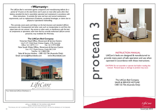
The LiftCare Bed Company Victorian Head Office, Showroom & Service Centre Unit 9, 271 Wells Road, Chelsea Heights, 3196, Australia Office: +61 3 8773 1111 Fax: +61 3 9773 4008
New South Wales Office,, Showroom & Service Centre Unit 119, 7 Hoyle Avenue, Castle Hill, 2154 Tele/Fax: +61 2 8850 5981
Sales & Service Hotline : 1300 132 736 (Australia Only) Email: [email protected] www.liftcarebeds.com
protean 3
This LiftCare Bed is warranted against component and manufacturing defects for a period of 10 years on the steel frame and 5 years on most other parts other than battery, provided the bed is assembled, operated and maintained in accordance with these instructions. It excludes fair wear and tear and normal maintenance requirements, such as replacement of batteries, accidental breakages, or claims due to physical or operational mishandling.
INSTRUCTION MANUAL LiftCare’s beds are designed & manufactured to provide many years of safe operation and use when operated in accordance with these instructions. CAUTION! Do not assemble or operate bed before reading this manual. Personal injury or damage to product may occur.
The LiftCare Bed Company SALES & SERVICE HOTLINE 1300 132 736 (Australia Only)
Your Authorised LiftCare Distributor is:
LiftCare. A MEMBER OF THE HUMAN CARE GROUP. Protean 3 INSTRUCTION MANUAL JULY 2010 THIS MANUAL MAY NOT BE REPRODUCED IN PART OR IN WHOLE WITHOUT THE WRITTEN PERMISSION OF THE PUBLISHER. 24
LiftCare. A MEMBER OF THE HUMAN CARE GROUP. Protean 3 INSTRUCTION MANUAL JULY 2010 THIS MANUAL MAY NOT BE REPRODUCED IN PART OR IN WHOLE WITHOUT THE WRITTEN PERMISSION OF THE PUBLISHER. Issued July 20101
GENERAL SPECIFICATIONS
Protean 3 True Floor Level Folding Electric Bed Electric Backrest Steering Castor/ Directional Lock (1) Green Left Hand side of bed head
Nominal Specifications (mm/inches-kg/lbs/ stone) Length between Head/Foot boards* (Standard)
2000mm/79”/6’7”
Length between Head/Foot boards* (Fully Extended)
2175mm/86” /7’2”
Platform Width (excluding mattress retainers)
900mm/35”/2’11½”
Overall Bed Width
925mm/36”/3’
Overall Bed Length (Standard-Extended)* Lowest Mattress Platform Height
Head & Foot Pedestal ends & caps
Lower cross beam beneath pedestal
Electric Kneebreak (option) Mattress retainers (4) Removable Head & Footboards (2) Braked Castors (3)
85mm/3½”
Highest Platform Height 125mm/5” castors
785mm/31”/2’7”
Platform Width ( incl. mattress retainers)
905mm/35½”/2’11½”
Overall Weight of bed**
138kgs/306lbs/21stone 12lbs
Mattress platform weight
54.1Kg/120lbs
Bed Base weight
84.9Kg/185lbs
Bed Operating Voltage
Max. 24 volts DC
Mains input Voltage (Subject to destination) Mains Power Amps
Remote Handset
2325mm-2500mm/ 91½”-98½”/7’7½”-8’2½”
220-240 volts/110 volts 1.5 Amps
Mattress Platform Panel Angles: Backrest Thigh Knee Calf Trendelenburg/Reverse Trendelenburg
70° 45° 110° 25° 18°
Maximum Operating Loads 1. Lower beam hinging with pins & lanyards
3. “J” hook or growth link plates
2. Upper beam central hinge
6. Mattress platform Circlips
250kg/550lbs/39stone
Corner or Side of Backrest
25kg /55lbs/3stone 9lbs
*Beds are shipped normally in standard length (sleeping space 2000mm/79”/6’7”) but can be extended to 2175mm/86”/7’2”) with the addition of an Optional Extension Kit and Bolster. **Not including accessory weight.
4. Platform fixing bolts 5. Lower beam Nylok nuts (4)
Mattress Base & Bed
7. Mattress platform pins
Maximum Lifting Capacity when raising or lowering bed base 250kg /550lbs/39stone 9lbs and on corner edge of backrest when adjusting angle 25kg/55lbs/3 stone 9lbs. All measurements are subject to commercial manufacturing tolerances. E&OE. It is the policy of the company to constantly improve the products to meet and exceed clients expectations. We therefore reserve the right to change the design/specifications of products without notice.
Serial No: Serial Number is located on the lower beam at the headrest end and is required when requesting Service.
LiftCare. A MEMBER OF THE HUMAN CARE GROUP. Protean 3 INSTRUCTION MANUAL JULY 2010 THIS MANUAL MAY NOT BE REPRODUCED IN PART OR IN WHOLE WITHOUT THE WRITTEN PERMISSION OF THE PUBLISHER. 2
LiftCare. A MEMBER OF THE HUMAN CARE GROUP. Protean 3 INSTRUCTION MANUAL JULY 2010 THIS MANUAL MAY NOT BE REPRODUCED IN PART OR IN WHOLE WITHOUT THE WRITTEN PERMISSION OF THE PUBLISHER. 23
EC Declaration of Conformity We, The LiftCare Bed Company A Division of Gerontic & General Products Pty. Ltd. Unit 9, 271 Wells Road, Chelsea Heights, 3196 Victoria, Australia hereby declare that the product in the version named below Protean 3 Floor Level Folding Electric Bed with its mechanical and electrical adjustment devices complies with the regulations of the EC Directive 93/42/EEC for Medical Products This bed is categorised as a Class 1 Medical Product. Applied Harmonized Standards AS/NZS 3200.2.38:2007 Medical Electrical Equipment- particular requirements for safety-Electrically and manually operated medical beds for adult use (IEC 60601-2-38, Ed.1.0 (1996) MOD) EN6061-2-38:1998 Medical Electrical Equipment-Part 2 Particular Requirements for the Safety of Electrically Operated Hospital Beds. Melbourne, 2010
1. 2. 3. 4. 5. 6. 7. 8. 9. 10. 11. 12. 13. 14. 15. 16.
CONTENTS Foreword...4 General Information ... 5 Safety Advice...6-7 Product Description ... 8 Accessories ...9-10 Putting bed into Service ... 11 Check List for Inspection ...12 Battery Backup ...13 Castors ...13 Handset Controls ...14 Unpacking the Bed ...15 Assembling & Unfolding the bed ...16-17 Folding Bed for Storage/Transport...18-19 Extending Bed Length ... 20-21 Declaration of Conformity ...22 General Specifications ...23
THIS BED GOES DOWN TO THE FLOOR-DO NOT PUT ANYTHING UNDERNEATH IT AT ANY TIME DO NOT .. • use or operate bed controls if head & foot boards are not in place • allow any cables, cords, or other obstructions to interfere with bed movement which must be unimpeded at all times. • run over toes. • pull or push the bed towards persons moving the bed. [Proper footwear should be worn.] • lower bed to minimum height if feet or any object is under mattress base. • place feet on castor support frames (outrigger) at any time. • move the bed until brakes are unlocked & mattress platform is at least 200mm clear of the floor • open or tamper with any part of the bed as this may be dangerous and invalidate the
•
warranty. sit on bed edges when back rest is being raised
ALWAYS ENSURE .. • the assembled bed is only lifted by its pedestal ends under castor support and lower cross beam beneath pedestal. • no parts of any person's body are beneath mattress base, backrest, Kneebreak (if fitted) or castor outrigger when bed is operating. • self-help and IV poles are lowered or removed if moving under low doorways or near equipment or low lights. • all locking bolts and other fasteners are fully engaged and correctly tightened before use • battery is plugged into control box (if fitted)
DO NOT USE FORKLIFTS OR MECHANICAL HANDLING EQUIPMENT TO LIFT THIS BED UNLESS IN ITS ORIGINAL CARTON LiftCare. A MEMBER OF THE HUMAN CARE GROUP. Protean 3 INSTRUCTION MANUAL JULY 2010 THIS MANUAL MAY NOT BE REPRODUCED IN PART OR IN WHOLE WITHOUT THE WRITTEN PERMISSION OF THE PUBLISHER. 22
LiftCare. A MEMBER OF THE HUMAN CARE GROUP. Protean 3 INSTRUCTION MANUAL JULY 2010 THIS MANUAL MAY NOT BE REPRODUCED IN PART OR IN WHOLE WITHOUT THE WRITTEN PERMISSION OF THE PUBLISHER. 3
FOREWORD
LiftCare would like to thank you for the confidence you have placed in us and our products in deciding to purchase this Protean bed. We are sure your investment in this high quality and durable product will provide you with many years of excellent cost effective service. Each bed has been tested for safety and functionality and has left our factory in perfect condition. This Instruction Manual informs you, as the operator, and your users, about all the functions necessary to ensure ease of operation and safe handling of this healthcare bed in its normal expected environment. You should therefore also regard this Instruction Manual as a practical reference book to be kept near the bed and readily available at all times, for anyone involved in its use or operation. We wish you and those using the bed every success in looking after your patients, residents or guests in a safe and comfortable, multifunctional bed.
The LiftCare Bed Company
LiftCare. A MEMBER OF THE HUMAN CARE GROUP. Protean 3 INSTRUCTION MANUAL JULY 2010 THIS MANUAL MAY NOT BE REPRODUCED IN PART OR IN WHOLE WITHOUT THE WRITTEN PERMISSION OF THE PUBLISHER. 4
LiftCare. A MEMBER OF THE HUMAN CARE GROUP. Protean 3 INSTRUCTION MANUAL JULY 2010 THIS MANUAL MAY NOT BE REPRODUCED IN PART OR IN WHOLE WITHOUT THE WRITTEN PERMISSION OF THE PUBLISHER. 21
GENERAL INFORMATION
EXTENDING THE BED EXTENDING OR REDUCING THE BED LENGTH:
•
Extend lower beams, replace the 4 pins in the outermost holes, replace the circlips pic 5.
The bed is normally supplied at its standard length of 2000mm (6’7”) measured internally between head and footboard. The bed is designed to be extended to 2175mm (7’2”) to accommodate taller people by the addition of an optional Extension Kit measuring 175mm which is fitted to the top beam of the mattress platform. The lower beam has a built in adjustment (“saddle & pins” - see pic 1 Page 2). Extending or reducing the bed length requires two people and circlip pliers to remove the pivot pins.
•
Remove the 2 circlips on the head end of lower beam saddle then remove all 4 pins (lower beams are now extended) pic 6.
•
Remove mattress platform locking bolts and fit to the extension brackets pic 7.
•
Remove mattress platform standard brackets at the foot end and replace them with the extension brackets, note that the support tab sits under platform pic 8.
NOTE: Some beds have pivot pin and Circlip and require needle point Circlip pliers
•
Fit the extension panel with the button head screws and nyloc nuts pic 9.
•
Using 2 people replace the extended mattress platform, foot end first ensuring that nylon bushes are in the hooks - Do not over tighten locking bolts pic 10.
•
Replace backrest and kneebreak cables into actuator connectors. Mattress and bolster can be placed on bed pic 11.
•
Check all bed functions. Note: The standard length beam brackets should be kept so that the bed can be returned to it's standard length.
FITTING EXTENSION KIT •
Check contents of the kit.
•
Remove head & foot boards.
•
Release backrest & kneebreak cables from actuators by removing plastic circlip in the connector.
•
Loosen mattress platform locking bolts pic 1.
•
Swing the link brackets away at head end and lower mattress platform onto lower beams at head end pic 2.
•
Using 2 people remove mattress platform, place it on a work bench or table pic 3.
•
Remove the 2 circlips on the foot end of the lower beam saddle, remove all 4 pins pic 4.
LiftCare. A MEMBER OF THE HUMAN CARE GROUP. Protean 3 INSTRUCTION MANUAL JULY 2010 THIS MANUAL MAY NOT BE REPRODUCED IN PART OR IN WHOLE WITHOUT THE WRITTEN PERMISSION OF THE PUBLISHER. 20
The PROTEAN 3 bed, referred to as the Instructions for the operator: ‘bed’, is manufactured in different versions. Any piece of technical equipment, electrical This Instruction Manual has been issued to or otherwise, can prove hazardous if not cover the different versions and accessories properly operated in accordance with its which are available for fitting to the bed. It Instruction Manual. is possible that certain functions or features may be described which your model does not incorporate. Please check your order Explanation of the groups of information if in doubt. persons names:
Operator-(eg: clinic, hospital, hospital
BEFORE PUTTING THIS BED management, nursing home), is every natural INTO SERVICE FOR THE FIRST or legal person with property rights over the bed (including when subject to hiring, TIME: rental or lease arrangements). • Read through this Responsibility for the safe operation of this Instruction Manual bed lies with the operator. from start to finish so as to User- (specialist medical staff, nurses, prevent damage or injury doctors, attendants, care staff) are persons who, on the basis of their training, due to incorrect operation. experience or thorough instruction, are • Clean and disinfect the bed entitled to operate the bed on their own responsibility or to carry out work on it, or prior to first-time use. who have received instruction in the handling of this bed. Furthermore, they are It is recommended that the bed is checked able to recognize and avoid possible hazards to be fully functioning and in perfect working as well as assess the clinical condition of the order before allocating for service. patients. This bed fulfils the requirements of the AS/ NZS 3200.2.38:2007 for Class 1 Medical Patient, Resident or Guest Devices and is CE complianced. Please also pay attention to your obligations In this manual a patient is described as any as the operator in order to ensure the person being ill, infirm, disabled, in need of permanently safe operation of this medical care, or otherwise occupying this bed. product with no risk to the patient, user and/or third parties. Each time the bed is This Instruction Manual contains safety allocated, it is advice which must be followed. All those involved with the bed must acquaint recommended that the themselves with the contents of this patient is instructed in the Instruction Manual and follow the Safety functions important for him/her advice provided.
by the operator or the user.
LiftCare. A MEMBER OF THE HUMAN CARE GROUP. Protean 3 INSTRUCTION MANUAL JULY 2010 THIS MANUAL MAY NOT BE REPRODUCED IN PART OR IN WHOLE WITHOUT THE WRITTEN PERMISSION OF THE PUBLISHER. 5
SAFETY ADVICE At the time of leaving the factory, this bed the electrical drives and side rails (if fitted). represents state of the art technology and LiftCare strongly advises against the use of side innovation. The most important objective of rails. Use of incompatible side rails can cause the safety advice is to prevent injury. hazard. Pay attention to your obligations in order to Safety Symbols ensure the permanently safe operation of this In this Manual the following safety medical product with no risk to the patient, symbol is used as: user and/or third parties. If the bed is in long-term use, it is important 1. Warning of injury to persons after a reasonable period of time to test the This symbol warns about the hazard of functions and check for functional electrical voltage and other significant hazards. and visual damage (see Page 12) There is danger to life. Only allow this bed to be used by persons who have been instructed in its safe operation. 2. Warning about general hazards • Make sure that stand-in or This symbol warns about general hazards. temporary staff are sufficiently There is danger to life and health. This symbol well instructed in the safe warns about possible damage to property. It is operation of the bed. possible that damage to the drive, materials or
platform or flat on the ground. FOLDING THE BED BASE •
•
•
•
the environment may be incurred. Safety Advice for the User Other advice • Make sure that the operator instructs you This symbol indicated a generally useful tip. If in the safe operation of this bed. you follow it, you will find it easier to handle • Each time before using the bed, check that the bed. This tip is provided for your better it is in perfect working order (see Page 12) understanding. • Bed should be left in it’s lowest position The safety symbol cannot replace the written safety advice. You are, when the patient is unattended. therefore, instructed to read the safety advice and follow it precisely. If any damage or a malfunction is suspected, immediately unplug from the mains supply, mark the bed clearly as Safety Advice for the Operator: being “OUT OF ORDER” and take it out With the aid of this Manual, which must be of service. Report this to the operator handed over together with the bed, immediately. you must ensure that every user is instructed in the safe operation of the bed before it is put into service THIS BED GOES DOWN TO THE FLOOR-DO NOT PUT for the first time. Draw every user’s attention to the possible ANYTHING UNDERNEATH IT AT hazards that can arise if the bed is not used ANY TIME. properly. This applies in particular to using
LiftCare. A MEMBER OF THE HUMAN CARE GROUP. Protean 3 INSTRUCTION MANUAL JULY 2010 THIS MANUAL MAY NOT BE REPRODUCED IN PART OR IN WHOLE WITHOUT THE WRITTEN PERMISSION OF THE PUBLISHER. 6
•
•
•
•
“saddle”. This will bring the beams to the vertical position and bring the pedestal ends together so that the folded bed base is standing on its four castors. Replace pins in the hinge saddle section.
Loosen the lower beam brackets near the pedestal ends, approximately one and a half turns of the Nylok nut with a • 17mm spanner. Remove the pins from the hinge saddle NOTE: The pins will be a tight fit and section. you will need to gently raise the Locate the actuator cable running along centre section of the platform to get the beam and ensure it is lowered the pins in. The platform is designed underneath the hinge bolts to avoid to have a small positive camber in the stretching or breaking the cable as the centre. This is a deliberate design feature and part of the integral bed base is folded. strength of the bed. After initial Standing at the side of one loading and use the camber will pedestal end of the bed, hold the pedestal end cap at the decrease slightly. top of the pedestal with one Lock all castors for safety until ready to hand and with the other hand reach move the bed. down and firmly lift the cross bar joining the two lower beams to disengage it from its locked position CLEANING enabling the pedestal end to fold down LiftCare beds can be safely cleaned flat onto the lower beams. with all commonly used dilutions of Rotate the snap latch with the “C” normal hospital cleaning agents. shaped cut-out located on the lower beam and swing it onto the lock on the LiftCare beds are not intendpedestal end ed for use with high pressure steam or jet-stream washing Repeat the above for the other end of procedures. the bed. Release the lock from one pair of • Do not pour liquids on any part of the castors ONLY at one end of the bed. bed end panels etc. which could damage With one person standing each side of the electronics. • Clean the bed by wiping surfaces with the centre hinging section of appropriate hygienic cloth moistened the lower beams, pull up on with normal hospital disinfectant. the metal cross bar on the inside of the each hinge
LiftCare. A MEMBER OF THE HUMAN CARE GROUP. Protean 3 INSTRUCTION MANUAL JULY 2010 THIS MANUAL MAY NOT BE REPRODUCED IN PART OR IN WHOLE WITHOUT THE WRITTEN PERMISSION OF THE PUBLISHER. 19
FOLDING THE BED This bed is designed to be folded for transport, storage or relocation.
5mm Allen Key-supplied with this Manual).
REMOVING THE MATTRESS • Lower the platform to approximately PLATFORM 100mm from the floor. • Ensure all castors are locked for safety. • Lift the mattress platform at the head • Place a protective blanket or padding on end and swing the “J” hook or growth the floor to ensure no damage to the link plates (see pic 3. Page 2) off and paintwork on the bed. away (at head end). • With the mains power connected, raise the • Disconnect the platform at the foot bed using the hand control so that the end by lifting and sliding the platform lower beams are approximately 300mm (1’) towards the head end. from the floor. • Remove all bedding and accessories eg: IV • Lift platform 50mm up and sideways 200mm (this needs two people). pole or Self Help Pole. • Lower the backrest and Kneebreak (if • Lift platform from side and swing fitted) to the flat position. upwards on its edge (two people) • Remove the head and foot boards • Ensure the “J” hooks are put back into • Remove the actuator cables from under the the original position on each pedestal beams. There is usually two plastic hooks end. Failure to do this may damage holding these cables; one near the bed. headboard on the beam and the other is FOLDING THE MATTRESS located under the sub-frame and can be seen from underneath the bed. PLATFORM • Once the cables have been released from NOTE: If bed is to be the clips, disconnect the mini-fit actuator fitted into a standard LiftCare plugs. A small flat head screwdriver is Protean Carton, platform needs required to release the ’O-ring lock’ within the mini-fit actuator plug. Push the to be fully lowered. screwdriver blade into the slot on the side • Take care not to damage the bed when of the plug which releases the ‘O-ring’ then removing the platform and ensure all pull the plug downwards to release. DO NOT TURN THE SCREWDRIVER BLADE OR THE PLUG WILL BREAK •
Leaving the bed at the 300mm (1’) height, take the weight of the platform off the beam and loosen 4 platform fixing bolts (see Pic 4 on page 2) at each corner of the mattress platform, using 17mm spanner.
Do not remove bolts. (Some models may have Allen head screws & require a
hinged sections are held securely when tilting the platform over so that they do not ‘flap’ loose and cause injury.
• Safely secure the two pairs of beam ends
and platform panels with cable ties, rope or other secure strapping. For safety, rest the folded mattress platform either on its side with the backrest at 45 degree angle to the rest of the
LiftCare. A MEMBER OF THE HUMAN CARE GROUP. Protean 3 INSTRUCTION MANUAL JULY 2010 THIS MANUAL MAY NOT BE REPRODUCED IN PART OR IN WHOLE WITHOUT THE WRITTEN PERMISSION OF THE PUBLISHER. 18
Make sure that there are no safely or free themselves from potentially obstacles eg: bedside lockers, dangerous positions chairs, hoists, wall mounted • the patient could be placed at risk through fixtures or equipment etc which inadvertent adjustment of the electric could impede any adjustment of the bed. motors. When using external electrical equipment, • the side rails are raised (risk of limbs such as patient hoists / lifts, reading lamps etc, getting trapped or crushed on adjusting make sure that the electrical cables cannot get the back and leg rests). (LiftCare strongly caught up in or damaged by parts of the bed. recommends against the use of side rails) The safe function of the bed and the external • children are left in the room with the components must be guaranteed. bed unsupervised (not recommended) • Route the mains cable in such a way that when operating the bed it cannot get pulled, be driven over or damaged by The adjustments may then only be carried out by or in the presence moving parts. of a person instructed in the • Before moving the bed, it is important to always unplug it from the mains power proper operation of the bed. supply and raise the mattress platform from its lowest floor position to at least At regular intervals carry out a visual inspection of the mains cable to check for 200mm/8”. mechanical damage (scuffing, bare wires, • Stow the mains cable safely in the clip on kinks, pressure points etc.) such a check the pedestal end of the bed to make sure should be performed: that it cannot trail on the floor. • whenever the cable has been subjected to • When not is use, stow the handset in such any mechanical load (eg: has been driven a way that it cannot inadvertently fall onto over by the bed itself or by an equipment the floor and make sure that the cable trolley, has been bent, stretched or cannot get damaged by moving parts of the violently pulled due to the bed being pulled bed. away while still plugged into the wall • Always make sure that the mattress socket). platform has travelled to its lowest • whenever the bed has been moved or position before leaving a patient in the bed relocated before plugging it back into the unattended. In this way you greatly reduce mains. the risk of patient injury as a result of • where the bed is in constant operation, at falling from bed. least once a week. To safeguard the patient, and particularly • check the strain relief of the mains cable children, against initiating power adjustments regularly to make sure the screws are tight of the bed inadvertently, place the handset and secure. beyond their reach (eg: at the foot end or block the adjustment options on the handset using the lockout key. (See page 10) if: • the patient is unable to operate the bed
LiftCare. A MEMBER OF THE HUMAN CARE GROUP. Protean 3 INSTRUCTION MANUAL JULY 2010 THIS MANUAL MAY NOT BE REPRODUCED IN PART OR IN WHOLE WITHOUT THE WRITTEN PERMISSION OF THE PUBLISHER. 7
PRODUCT DESCRIPTION Designated use This bed is designed for use in aged care, community care and private homes for the purposes of providing comfort and care for any adult person being ill, frail, disabled or in need of care. • the Safe Working Load (SWL) of this bed is 250kg/550lbs/39stone. Due allowance must be made for the mattress, bedding, accessories and visitors or carers sitting or putting extra weight on the bed, when considering normal maximum patient weight. It is not recommended to use this bed for patients over 200kg/ 440lbs/31 stone for which LiftCare has other suitable beds up to 455kg/1000lbs/71 stone Safe Working Load.
powder-coating. The head and foot end pedestal covers of the bed are ABS plastic. All the surfaces are non-harmful on coming into contact with the skin.
beams into the “J” hooks in the pedestal ends, one end at a time- bushes to the outside and tighten the
Structural Design
the platform to its highest position. Connect the backrest and kneebreak (if fitted) mini-fit actuator plugs and secure to the bed frame by the plastic clips.
Mattress Platform: The mattress platform is divided into a back rest, a split seat section, and on some models a thigh and calf section lift section (kneebreak or knee-gatch). The mattress base can be horizontally adjusted in height. The bed can be adjusted to a head-low or feet-low (Trendelenburg & reverse / Tilt) position. Chassis: The chassis is constructed of welded steel and features four individually locking castors (3 brake (red) and 1 Directional lock-usually green) •
Electrical adjustment system: The electric adjustment system of this bed • this bed may only be operated by persons comprises: who have received instruction in its safe • a handset for use by the patient. The operation. handset consists of a robust, easy-care, • the bed may only be operated under the wash-down plastic casing with membrane conditions of duty described in this manual. keypad. ANY OTHER USE SHALL BE • Motors for controlling the backrest and REGARDED AS NON-COMPLIANT kneebreak or knee-gatch, if fitted, WITH THE REQUIREMENTS AND MAY adjustments and the height of the bed. INVALIDATE WARRANTY. Application Environment: (IEC 60601-2-38 201.3.203 • The central control box unit (and battery and 201.3.204) backup, if fitted) are located underneath Application 3 Long-term care in a medical area the covers at the head end of the bed. where medical supervision is required and Here a transformer generates a safe low monitoring is provided if necessary and ME voltage of 24V which is non-harmful for EQUIPMENT used in medical procedures may be both the patient and user. Connected to provided to help maintain or improve the condition the central control unit, via dust and of the PATIENT. moisture proof plugs, are all the electric Application 4 Care provided in a domestic area where ME EQUIPMENT is used to alleviate or motors and the handset which work on a compensate for an injury, disability or disease. safe low voltage of 24V. • Battery backup (if fitted) allows for offMaterials in the bed mains emergency operation (for a limited The bed is built for the most part from steel, period of time). or stainless steel, the surface of which has been finished with an electro-coated LiftCare. A MEMBER OF THE HUMAN CARE GROUP. Protean 3 INSTRUCTION MANUAL JULY 2010 THIS MANUAL MAY NOT BE REPRODUCED IN PART OR IN WHOLE WITHOUT THE WRITTEN PERMISSION OF THE PUBLISHER. 8
•
bolt. The plastic bushes should be pulled into the “J” slot when tightening. Lift the beam to assist with this, and ensure bushes are fully seated. Attach the mains cable to the mains power supply checking that it has not been damaged in transit.
Install head and foot boards by lowering them into the bracket slots on the inside of each pedestal end. NOTE: Re-check all screws, levers, bolts & attachments are securely tightened. •
•
•
Operate the lift button (usually the fourth button) on the handset to raise
• •
• •
Read the Operations Section and check all operations of the handset are working correctly and quietly to the full travel range of adjustment to height, backrest and kneebreak (if fitted). Check Trendelenburg (Tilt) positions. Lower the mattress platform to the floor and ensure it is perfectly horizontal. Add any supplied accessories such as Self Help Pole, IV Pole, etc. Ensure bed is fully cleaned and ready for use before placing the mattress on the bed and making the bed.
LiftCare. A MEMBER OF THE HUMAN CARE GROUP. Protean 3 INSTRUCTION MANUAL JULY 2010 THIS MANUAL MAY NOT BE REPRODUCED IN PART OR IN WHOLE WITHOUT THE WRITTEN PERMISSION OF THE PUBLISHER. 17
ASSEMBLING & UNFOLDING THE BED (REQUIRES TWO
ACCESSORIES & OPTIONS
PEOPLE)
Assembling the mattress platform • • Carefully remove from carton, if packed
With one person at each end, stand the platform on its side alongside and parallel to the bed base with the back rest to the head end of the bed base where the electrical control box and handset are located.
this way, then with the folded mattress platform on its side edge, remove the security ties and other packaging. • Remove the pins from the centre hinging section. • Unfold the mattress platform until the HINT! Protect the surface of the beams a r e lower beams with cardboard or straight then lay material before lowering the the mattress mattress platform onto the lower platform down beams on flat ground with the beams facing down • Carefully turn and lower the platform to rest onto the bed base lower beams and re-insert so the mattress surface is facing up and the circlips and the actuators are underneath. pins. NOTE: both mattress platform beams need to sit over and outside the lower beams on the base. NOTE: The pins will be a tight fit and you will need to gently raise the • Manually lift and support the platform sections (backrest and foot end panels) centre section of the platform to get vertically to make access to the beam each pin in. The platform is designed ends easier. Tighten the foot end to have a small positive camber in the beam Allen screws first when putting centre. This is a deliberate design the mattress platform on. feature and part of the integral strength of the bed. After initial loading and use the camber will NOTE: the head has swinging beam decrease slightly. end (“J” hook or growth link) which allows some adjustment once the beams are set in place in the “J” hook • Make sure the platform and the bed slots. base are in the same position ‘head end • Slot the bolts with the plastic bushes at to head end’. the end of the mattress platform LiftCare. A MEMBER OF THE HUMAN CARE GROUP. Protean 3 INSTRUCTION MANUAL JULY 2010 THIS MANUAL MAY NOT BE REPRODUCED IN PART OR IN WHOLE WITHOUT THE WRITTEN PERMISSION OF THE PUBLISHER. 16
LiftCare’s beds are designed to be fitted with various accessories and options to assist with the care and comfort of patients. It is important that only LiftCare accessories are fitted to these beds as any incompatible accessories could cause damage and/or injury. Self Help Pole: The self help pole when fitted is intended to assist a patient moving within the confines of the bed. It is not to be used for any other purpose. The self help pole provided by LiftCare has a safe working load of 75 kg’s. IV Pole: An adjustable IV Pole can be fitted to the bed (2 at either end of the bed). It is important to only use LiftCare IV Pole as any
Side Rails: LIFTCARE STRONGLY RECCOMENDS AGAINST THE USE OF SIDE RAILS AS THEY CAUSE DEATH AND INJURY. LiftCare is aware that, in some cases, side rails can be required for care but only authentic LiftCare side rails should be fitted to floor level beds as any incompatible side rails could cause damage and/or injury.
Kneebreak:
incompatible IV poles could cause damage and/or injury. The safe working load of LiftCare’s IV pole is 7kg.
When fitted with a kneebreak, the Protean bed combines comfort & functionality for patient and carer. Kneebreak allows the Protean to be positioned as a cardiac chair even when the bed is at it’s lowest position.
Care Assist Rail: Designed to assist patients safely in and out of bed. Ergonomically designed and low profile to avoid feeling restricted or restrained.
LiftCare. A MEMBER OF THE HUMAN CARE GROUP. Protean 3 INSTRUCTION MANUAL JULY 2010 THIS MANUAL MAY NOT BE REPRODUCED IN PART OR IN WHOLE WITHOUT THE WRITTEN PERMISSION OF THE PUBLISHER. 9
UNPACKING THE BED
ACCESSORIES & OPTIONS Battery Backup:
Wall Bumper Bar:
Battery Backup, when fitted, allows for continuous operation of the bed should mains power fail or if the bed is being operated temporarily away from mains power. To ensure long life, beds fitted with battery backup must remain connected to mains power at all times.
Protean 3 can be fitted with a single wall protecting bar at the head end to prevent damage. This bumper bar is fitted to the lower cross beam between the castors.
Extension Kit: LiftCare’s beds can be extended to provide extra comfort for taller patients. The kit comes complete with instructions and requires tools for fitting. The sleeping space of the bed is extended by 175mm with the addition of this kit. (See page 20 for fitting instructions)
Mattresses: This bed is designed for use with mattress(es) of specific dimension and type. See labelling on bed. LiftCare’s beds are designed for mattresses measuring 1980mm long by 900mm wide and 125mm deep. It is imperative to use this size mattress to reduce the risk of entrapment and falls.* WARNING: Incompatible mattresses can cause hazards.
The LiftCare range of mattresses provide superior support and comfort Push Handle: as well as possessing intrinsic antiA multi position push handle can be fitted to the foot end of a Protean to assist with bacterial properties. LiftCare mattresses contain no latex. Our the manoeuvrability of the bed. mattresses are covered in fabrics designed for health care which are: • Fluidproof • Flame retardant • Stain & Tear resistant • Cover impregnated with antibacterial and anti-fungal agents • Antistatic Dual Wheel Castors: Enclosed 125 • Comfortable mm dual wheel • Durable solid construction castors are • Flexibility available for the Protean.
*When fitted with Extension Kit a matching bolster is available measuring 175mm long by 900mm wide by 125mm deep.
• It may be necessary when the beams are Hint-assemble near mains power! The bed, when shipped folded, is in two nearly horizontal to lift the pedestal ends parts-the bed base and folded mattress vertically to “unlock” the hinged beam ends. platform. (Packing method is dependent NOTE: The pins will be a tight fit and you upon destination). will need to gently raise the split centre Ensure bed has been delivered with the section of the beam to get the pins in. cartons in correct position as marked on the outside of the cartons. Some beds are DO NOT LOWER THE BED WITH delivered without cartons. Check no external THE HANDSET AT THIS STAGE OR damage is visible. DAMAGE WILL OCCUR
Assembling the bed base • Standing
NOTE: Read the Operating instructions section prior to assembly. • Ensure all castors are locked for safety. • Remove the circlip and pin from each side of
the saddle on the lower beam.
at the side of the pedestal end, holding the plastic end cap at the top of the pedestal with one hand, with the other hand reach down and firmly lift the cross bar joining the two lower beams to engage it into its locked position with the pedestal brackets so the pedestal remains locked upright.
• With
ONLY RAISE THE BED TO APPROXIMATELY 150MM/6” TO ASSIST WITH ASSEMBLY.
the other pedestal end, raise the pedestal into the vertical position and engage it into the brackets as in the previous step.
• Tighten the lower beam brackets near the • Release the lock on the red castor at the
head end of the bed (ie: the end of the bed with one red castor and one green castor) leaving the green directional castor locked. • Carefully
pull the unlocked pedestal end away from the other pedestal, to flatten the main lower beam, with one person on each side to help as the pedestal end moves away from the other end.
pedestal ends with the 4 Nylok nuts, (see Pic 5. page 2) ensuring the pedestals are properly engaged in the beam brackets, by firmly pushing the beams down prior to locking in place. You may need to loosen the nuts to achieve this.
• Unlock the ‘transport latch’ (latch may differ
on some models ) holding the beam against the pedestal ends. Swing the latch to one side to be parallel to the beams. • Replace circlip & pins into the lower beam
hinges.
LiftCare. A MEMBER OF THE HUMAN CARE GROUP. Protean 3 INSTRUCTION MANUAL JULY 2010 THIS MANUAL MAY NOT BE REPRODUCED IN PART OR IN WHOLE WITHOUT THE WRITTEN PERMISSION OF THE PUBLISHER. 10
LiftCare. A MEMBER OF THE HUMAN CARE GROUP. Protean 3 INSTRUCTION MANUAL JULY 2010 THIS MANUAL MAY NOT BE REPRODUCED IN PART OR IN WHOLE WITHOUT THE WRITTEN PERMISSION OF THE PUBLISHER. 15
PUTTING THE BED INTO SERVICE The handset provided with the bed has a small blue plastic ‘lock out key’. To lock any function on the bed, insert the key into the two holes in the button(s) you wish to lock out and turn gently from the ‘green / 12 o’clock position toward the lock or unlock position-(ie: 11 or 1 o’clock). Use only sufficient pressure to turn the lock on the button otherwise the tab on the key may break. Top button operates the backrest-press the raise or lower key to adjust
Second button operates the Kneebreak (if fitted) - press the raise or lower key to adjust
Third button raises and lowers the Kneebreak & backrest simultaneously (‘autocontour’) -press the raise or lower key to adjust both sections of the bed
Fifth button operates the Trendelenburg & reverse (tilt)-press the raise or lower key to adjust
Kneebreak (option-second button) Ensure a LiftCare recommended mattress is used as other mattresses may cause damage or injury, particularly if kneebreak is fitted. Note: Handsets supplied have buttons for kneebreak which are inactive if the kneebreak mechanism is not fitted. When the bed or individual sections of the bed have reached the desired position release the button to stop movement. • When not in use, the handset is designed to clip over the mattress retainers at the side of the mattress platform. • When maximum raised or lowered positions of mattress base or backrest are reached, a built-in limit switch will automatically override the handset button and movement will stop. DO NOT CONTINUE TO PRESS BUTTON. • Movement in the opposite direction will be resumed when the appropriate button is pressed.
Before putting the bed into service for the first power supply. (Only then can you be sure time. that the bed’s battery backup (if fitted) is 1. Remove all transport securing devices and adequately charged and ready for operapackaging material. tion.) 2. Fully assemble & test the bed (see page 16- • there are no obstacles, eg: bedside cabinets, chairs, wall fixtures, etc which could 17) 3. Clean and disinfect the bed prior to first impede adjustment of the bed. • all the adjustment functions have been time use. tested and are working properly. (See Each time before putting the bed back into Checklist on page 12) service, the user much check that: Provided the above has been complied • bed castors are locked with, the bed may now be put into ser• electricity supply is compatible with the vice. bed • mains power supply is • Insert the plug into the power point. OFF (Australian socket • Turn ON the switch at the power shown but suitable point. electrical systems are • Test all the adjustment functions are supplied as appropriate to client’s markets). working properly. (See Checklist page 7) • mains power supply cable is connected and • Secure all pins, bolts and fasteners. routed so that it cannot be damaged The bed should be connected to the • mains power supply cable, motor cables mains power which is switched on at and handset cable cannot get damaged on all times. bed parts • bed is permanently connected to the mains
RELEASE THE HANDSET BUTTON TO IMMEDIATELY STOP MOVEMENT Fourth button operates the Hi/Lo mattress platform-press the raise or lower key to adjust up or AND/OR FUNCTIONS OF THE BED. down
LiftCare. A MEMBER OF THE HUMAN CARE GROUP. Protean 3 INSTRUCTION MANUAL JULY 2010 THIS MANUAL MAY NOT BE REPRODUCED IN PART OR IN WHOLE WITHOUT THE WRITTEN PERMISSION OF THE PUBLISHER. 14
LiftCare. A MEMBER OF THE HUMAN CARE GROUP. Protean 3 INSTRUCTION MANUAL JULY 2010 THIS MANUAL MAY NOT BE REPRODUCED IN PART OR IN WHOLE WITHOUT THE WRITTEN PERMISSION OF THE PUBLISHER. 11
CHECK LIST-INSPECTION/MAINTENANCE BY THE USER Inspection should be carried out every 6 months for the life of the bed Care should be taken when performing the maintenance Checked
OK
NOT OK
Description of fault
Visual check of the electrical components Actuators
Damage
Control Box
Damage
Cables
Damage, routing
Handset
Damage
Visual check of the mechanical components Nuts & Bolts
Secure
Damage Mattress Platform is parallel to floor (ie level)
Chassis
Damage, deformations
Mattress Platform, covers
Damage
Castors
Damage
Bed Extension
Damage
Performance check of the electrical components Backrest
Adjustment, secure retention
Kneebreak (if fitted)
Adjustment, secure retention
Platform Hi/Lo
Adjustment, secure retention
Battery Backup ( if fitted) Check fully charged & operational Handset
Adjustment, secure retention
Accessories (eg: Self Help Pole, side rails)
Fastening, damage
Signature of the Inspector:
Battery Backup (option)
assist with steering.. Battery Backup is recommended to • If brakes are not released and the bed is ensure continuous operation of the beds forcibly moved when the wheels are locked even in the event of mains power supply the treads may be damaged. failure or interruption. • If leaving the bed for any time ensure • If the battery back-up option is fitted, the castors are turned inwards, and locked. bed can operate without mains power supply for a number of cycles before the batteries will become flat. Directional Lock • If batteries become flat because the mains The Directional Lock [usually power supply has inadvertently been disconnected, raising and lowering functions green] on one castor at the head end, should be engaged to the will slow down or will not operate and “ON” position at all times. batteries may need replacing. • Batteries in good condition will normally To control movement forwards or recharge overnight when the mains plug is properly reconnected to the power source. backwards only, orient this wheel so it is parallel with the side edge of the bed, Extended periods without mains power depress the lock “ON” lever, with your will make the batteries unable to be foot. This will engage a lock on this wheel recharged or operate at all. A which will permit the bed to run straight replacement unit will need to be forward or backward when being moved. The wheel itself can be positioned towards the ordered. front or the back of the castor outrigger but it is recommended to point down the bed’s Castors & Brakes length. • The bed is fitted with 3 To disengage the Directional Lock, red braked castors and 1 depress the “OFF” lever. green (usually) steering or directional castor. Handset Controls • Castors are braked and The remote handset, locked by depressing the connected to the front of the pedal on each castor lever. This is done by foot pressure control box, operates all electric functions. The functions when wearing appropriate protective shoes. and operation of the handset • Brakes are released by depressing the top of should be explained to the patient. the castor lever until it unlocks. The basic function of the buttons Do not attempt to set or release the brakes is to raise and lower the different using your hands or fingers. Before moving functions/parts of the bed. the bed, raise the mattress platform to a minimum of 200mm from the floor.
• When moving the bed, first release the
Name of Inspector:
Inspection result:
Date: LiftCare. A MEMBER OF THE HUMAN CARE GROUP. Protean 3 INSTRUCTION MANUAL JULY 2010
THIS MANUAL MAY NOT BE REPRODUCED IN PART OR IN WHOLE WITHOUT THE WRITTEN PERMISSION OF THE PUBLISHER. 12
OPERATION
brakes on all castors and the bed will move freely then re-engage the directional lock to LiftCare. A MEMBER OF THE HUMAN CARE GROUP. Protean 3 INSTRUCTION MANUAL JULY 2010 THIS MANUAL MAY NOT BE REPRODUCED IN PART OR IN WHOLE WITHOUT THE WRITTEN PERMISSION OF THE PUBLISHER. 13