User Manual and Technical Description
37 Pages
Preview
Page 1
______________________________________________________________
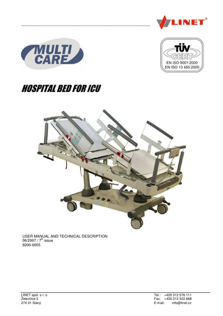
HOSPITAL BED FOR ICU
USER MANUAL AND TECHNICAL DESCRIPTION th 06/2007 / 7 issue 9200-0055
LINET spol. s r. o Želevčice 5 274 01 Slaný
Tel.: +420 312 576 111 Fax: +420 312 522 668 E-mail: [email protected]
________________________________________________________________________
Dear customer, We are pleased by your decision to buy this product from our company. We can assure you of the advantages of your carefully considered choice and you will be fully satisfied during the whole longevity of this product. Due to the exceptional design, careful selection of used materials, the most modern production technology, skilled workforce and multiple examinations, our products reach parameters which guarantee our customers top quality, durability and long term utility value.
user manual MULTICARE, 9200-0055
2
06/2007
______________________________________________________________________
CONTENTS 1. Introduction
5
2. Delivery
5
2.1 Specification of versions and options
6
3. Safety instructions
6
4. Conditions for use
7
5. Technical parameters
7
6. Bed description
8
7. Bed installation and setting up
9
7.1. Charging of battery backup
9
7.2. Equipotential Connection
9
8. Bed positioning
10
8.1. Supervisory Panel
10
8.1.1. Actual positioning
11
8.1.2. Memory-functions
11
8.1.2.1. Programmable positions
12
8.1.3. Follow up of life and charge of battery (Intelligent Battery Back-up)
12
8.1.4. Locking of control sets
12
8.1.5. Central STOP button
13
8.2. Action panel (anaesthesiologist panel)
13
8.3. Foot control set
13
8.4. Siderails control sets
14
8.5. Mechanical CPR unblocking of backrest and thighrest
14
8.6. Calfrest positioning
15
9. Battery back up
15
10. Integrated weighing of the patient
15
10.1. Basic Definitions
16
10.2. Panel Description
16
10.3. Preparation of the bed for the patient (resetting the primary and secondary displays)...17 10.4. Establishing the change in the patient’s weight (resetting the secondary display) 17 10.6. Bed Exit Alarm
17
10.7. Display Test
17
11. X-ray examination on the bed
18
11.1. X-ray examination with the classical mobile X-ray machine
18
11.1.1. X-ray cassette holder location on the mattress platform frame
18
11.1.2. X-ray cassette holder location on the backrest
19
11.1.3. Warnings and recommendations of manufacturer
19
11.2. Scanning by the C-arm
20
12. Siderails control
20
13. Bed extension
21
06/2007
3
user manual Multicare 9200-0055
________________________________________________________________________
14. Central castor control
22
15. Stainless steel bar
22
16. Accessories
23
16.1. Lifting Pole and IV Pole
23
16.2. Anti-decubitus mattress compressor holder
23
16.3. Plastic hooks for petit accessories
23
16.3.1. Holder of drainage pipes (cannula holder)
24
16.3.2. Stainless steel bar 26 cm
24
16.3.3. Urinal bag holder
24
16.3.4. Urinal bottle or slippers holder
24
16.4. Temperature board
25
16.5. Monitor shelf
25
16.6. Upholstery for siderails
25
16.7. Oxygen bottle holder
26
16.8. Shelf for writing
26
16.9. Multicare side-protector
26
17. Cleaning and disinfecting
27
17.1. Basic instructions before you start cleaning
27
17.2. Daily routine washing
27
17.3. Cleaning and disinfection after patient departure or transfer
27
18. Stand-by battery
28
19. Troubleshooting
29
20. Storing
30
21. Maintenance
30
22. Environmental protection
30
23. Warranty and Service
31
24. Bed labels positioning
32
25. Used marks and symbols
33
26. Record of service checks and routine maintenance
34
27. Protocol on hand-over of the MULTICARE bed
35
28. Contacts
35
Appendix I – the identification of places with increased risk of jamming or squeezing 36 EC CONFORMITY DECLARATION
user manual MULTICARE, 9200-0055
37
4
06/2007
______________________________________________________________________
1. Introduction The resuscitation MULTICARE bed is designed for the treatment of patients in critical condition. The bed allows the scanning of the patient by mobile X-ray or by C arm. The bed is equipped with lateral tilting and an integrated weighing scale (as option). All individual parts of the mattress platform, longitudinal and lateral tilting and height of the mattress platform can be adjusted by actuators. The bed is movable. The bed is in conformity with international standards EN 60601-1, EN 60601-2-38, EN 60601-1-2, EN 60601-1-4, EN ISO 10993. The product also meets all the requirements of directive 93/42/EEC, standard technical requirements for medical devices and 89/336/EEC, covering electromagnetic compatibility of devices. The production has been certified by a quality control system according to standards EN ISO 9001:2000 and EN ISO 13485:2000. Prior to bed operation the staff should acknowledge this Manual. All operations of the bed have to be done in conformity with this Manual! Any other action with or operation of the bed is done at the user’s risk and the producer cannot be responsible for damage of any kind. It is important to keep this Manual easily accessible to staff during the whole lifetime of the bed! The MULTICARE bed is manufactured in conformity with the norm EN 60601-1. Nevertheless the bed doesn’t fulfil this norm’s demand concerning the distances between movable parts. The reason for the accepted construction solution is the using of the following therapeutical functions: auto-regression of the backrest X-ray scanning of the patient Integrated weighing system As the protective measure was taken the location of warning symbols on the critical places and illustration of these places in the appendix I of this Manual. The bed is equipped with a lateral tilt function that is intended for preventive positioning of patients. Although the SWL of Multicare bed is 230 kg, the trouble free lateral tilt application is limited by the patient weight approx. 160 kg. It is necessary to respect this weight limit to prevent a danger of patient inadequate position. The bed can stay adjusted in lateral tilt, if the named weight limit is overreached. In such a situation use CPR memory function to reach the safe patient position. Notice: The producer reserves the right to make changes in this User Manual due to technical changes or improvements of the product. The content of this manual may differ in minor detail from the basic product design.
2. Delivery The bed is delivered assembled with removed bed-heads and accessories. The completion check, according to the delivery note, should be done immediately after the delivery to the destination. In case of any differences or damage the producer should be notified in writing. For unloading of the MULTICARE bed is necessary to use the lift platform truck or the pallet truck with load capacity of 500 kg. When loading and unloading the bed, or when moving the bed in any other way, make sure that the brakes of the castors are released (see part Central Braking System). The castors are designed for movement inside, on even, smooth and clean surfaces (ceramic tiles, linoleum, tiled floors). Movement on rough, uneven and dirty surfaces (i.e. roads) might seriously damage the castors. Running over the higher door sills might cause the damage of column motor units gripping.
06/2007
5
user manual Multicare 9200-0055
________________________________________________________________________
2.1 Specification of versions and options Multicare beds are defined by model product numbers. This number has the general form: 1HXXXXXXXXXXX and for the variables X there are defined variable features listed below: Variable features (equipment)
Options
Weighing system
Bed with weighing system Bed without weighing system
Mattress platform width
90 cm (broad version) 86 cm (narrow version)
3. Safety instructions Prior to usage of the bed the attendant should be familiar with the Manual for use and all operations of the bed should be done in conformity with the Manual. The bed must not be used in an explosion hazard environment or in the presence of inflammable anaesthetics. Do not use the bed if any fault is found, especially faults, which might cause injury to a patient, staff or any third person, or damage to the bed or other surrounding equipment. The bed can be operated by authorised staff only, having knowledge and experience enough for trouble free operation. The bed is intended for patients in critical condition, which requires the permanent medical staff monitoring of patient. If the monitoring is temporarily interrupted, the medical staff shall provide the patient safety by appropriate setting the bed – adjusting the minimal bed height and/or blocking the positioning functions on the supervisory panel. The attendant is obliged to train the patient in the control of functions designed for use by the patient. Prior to use, check if all the functions are in order. The bed should be used on even, smooth and clean surfaces only. The bed should not be overloaded even for a short period. When overloading is absolutely necessary (by reanimation), the mattress platform has to be set to the lowest position. If there is a patient on the bed, the castors should always be locked (with the exception of transporting the bed). If the bed is not locked, there is a danger of injury to the patient when standing up or leaning. Always lift up the side rails before lateral tilting; otherwise the patient can slip off. Do not overreach the patient weight limit 160 kg when adjusting a lateral tilt on the bed to prevent inappropriate patient positioning! If the IV rod, lifting pole or any other accessory is fixed to the bed, be sure when moving, lateral tilting or adjusting, that there is enough room around the bed. Before cleaning or maintenance always disconnect the power supply cable. It is not allowed to use the unoriginal spare parts for repairs of the bed. If some unoriginal or inapplicable parts and items are used, the producer will not be responsible for the possible damages or injuries. The patient or an attendant might be in danger, especially when: The power supply cable is damaged or worn out, Transporting on an unsteady surface Unauthorised maintenance (washing in automatic washers or by pressure water etc) is carried out The bed us overloaded There is unauthorised use There is careless adjustment of the height (pinching of leg in between the mattress platform and undercarriage) There is careless adjustment of the lateral tilting (lifting off of the side rails, slipping of the patient, damage to the accessories)
user manual MULTICARE, 9200-0055
6
06/2007
______________________________________________________________________
4. Conditions for use The bed should be located in an environment where:
the ambient temperature ranges from + 10°C to + 40° C relative humidity ranges from 30% to 75% atmospheric pressure ranges from 700 hPa to 1060 hPa
Any other use must be discussed with the manufacturer in advance. The bed must not be used in an explosion hazard environment or in the presence of inflammable anaesthetics. The bed is designed for use in rooms for medical purposes. The electric installation in these rooms must come up to concrete standards valid in the country of use. Nevertheless in exceptional cases (storm) we recommend to disconnect the bed from mains. Since the bed is operated electrically, the function of the sensitive devices could be influenced by the electromagnetic emission of the bed. To eliminate these effects, the bed is produced according to the standard EN 60601-1-2. To avoid these problems it is necessary to operate the bed according to the information contained in this Manual.
5. Technical parameters External dimensions
Extension of the bed Backrest – length / tilting angle / auto-regress Sitrest – length Thighrest – length / tilting angle Calfrest. length Height of mattress platform (without mattress) Height of siderails above mattress platform Trendelenburg position Anti-Trendelenburg position Lateral tilting Weight Max. loading of lifting pole Max. safe working load (including mattress and accessories) Max. weighting of the scale Accuracy of the scale – absolute mode - differential mode - time firmness in differential mode Max. dimensions of x-ray cassette
223,5 x 99,5 cm (narrow version) 223,5 x 105,5 cm (broad version) 200 x 86 x 12 cm (narrow version) 200 x 90 x 12 cm (broad version) 12 cm 80 cm / 75° / 10 cm 25 cm 36 cm / 45° 61cm 54 – 94 cm 41 cm 16° 25° +/-30° 240 kg 75 kg 230 kg 250 kg +/-0,2 kg +/-0,05 kg 24 hrs 46 x 38,5 cm
Power supply: Water and dust preventing: Classification: Actuators operating cycle:
230 V, +/- 10%, 50 Hz, 1,6 A IP X4 Class I, type B 10% max. 2 minutes in 18 minutes
Recommended mattress dimensions
If required as a custom option the Multicare beds can be delivered with different electrical parameters (power unit with different voltage, etc.) than are stated in the table above. The bed is operated electrically, and the function of sensitive devices could be influenced by the electromagnetic emission of the bed. To eliminate these effects, the bed has been produced according to EN 60601-1-2. To avoid any problems ensure the bed is operated as described in this User Manual.
06/2007
7
user manual Multicare 9200-0055
________________________________________________________________________
6. Bed description 1
11
2
12
3
13
4
5
6
14
7
8
15
16
9
17
10
18
19
Supervisory panel Foot end Divided siderails (foot part) Calfrest Thighrest with mechanical CPR releasing Divided siderails – head part with integrated control sets Sitrest Handles for CPR releasing of the back- and thigh-rest Backrest with auto-regression and mechanical CPR releasing Head end Scale control panel and displays for angles of lateral tilting, TR/ATR and backrest tilting Lever of central braking system Holder of lifting pole, IV stand or other accessories Plastic cover of undercarriage shaped for placing the oxygen bottle 10 l Foot controls Column actuator unit Castors 150 mm Holders of accessories Protective corner bumpers 125 mm
user manual MULTICARE, 9200-0055
8
06/2007
______________________________________________________________________
7. Bed installation and setting up It is necessary to leave the bed in the new environment, before use (before connecting to the power) for approximately 12 hours to adapt to the new environment (differences between external and internal temperatures). Remove the packaging of the bed Check the completeness of the delivery according to the delivery note. In the case of differences or defects, mark it on the delivery note or notify the producer or supplier in writing. Read the Manual for use carefully Assemble the bead heads and accessories Connect the bed to the mains, including the equipotential connection Charge the battery backup as is described in the following section Check functions: Adjust each part of the mattress platform to the maximum position, set the height of the mattress platform and tilting to the maximum and minimum position. Check the data on the maximum tilting angle and compare it to the data in the technical specification chart. Set the lateral tilting to the maximum and minimum position. Check the data on the maximum tilting angle and compare it to the data in the technical specification chart. Check the perfect function of the castors, central braking, extension of the mattress platform, locks of the head and foot ends and of the shelf. Check the set and lifting of the siderails. Check the electronic control of the bed. Examine all the control sets – the controls of the Supervisory panel, of the control sets on the siderails, the foot control set and the action control set at the head end. Step by step lock functions by the Supervisory panel and check the locking of functions and adjustment of all the others panels. Put a glass of known weight on the mattress platform. Set the scale to zero and fill the glass with water. The displayed data should be equal to the content of the water with the conversion 1l =1kg. This check is only an approximate test of functionality. The packaging should be ecologically disposed of. The Manual for use should be kept safely. Report any deficiency, damage or fault immediately to the transport company and to the supplier!
7.1. Charging of battery backup The beds are standardly delivered with battery back up connected to the power box. Prior to usage, the battery has to be charged by connecting the bed to the mains. A new battery has to be charged for 50 hours! It means that the bed shall be connected to the mains for 50 hours without any bed positioning!
7.2. Equipotential Connection The bed is equipped with a conductive interconnection of all individual parts thereby providing potential equalisation throughout the bed, so that the intravascular or intracardial connection of devices to patients can be safely made. The protective earth terminal designed for this purpose is located below the head end and is marked by the following symbol:
06/2007
9
user manual Multicare 9200-0055
________________________________________________________________________
8. Bed positioning The bed positioning (except the calf-rest) is undertaken by electric actuators. The control of these actuators is made using one of the available control sets: Supervisory panel, side-rail control, foot control or action (anaesthesiologist) panel. Individual control sets are described in the following chapters.
8.1. Supervisory Panel The Supervisory Panel is located at the foot end or it can be placed on siderails, too. 1
11
1 2 3 4 5 6 7 8 9 10 11 12 13 14 15 16 17
2
3
12
4
5
13
6
14
7
15
8
16
9
17
10
11
Button for locking the backrest positioning Pair of buttons for backrest positioning Button for locking the thighrest positioning Pair of buttons for thighrest positioning Pair of buttons for the control of simultaneous tilting of the backrest and thighrest (auto-contour). Green LED control – power supply on Pair of buttons for the longitudinal tilting of the mattress platform (Trendelenburg/Anti-Trendelenburg) Pair of buttons for the height adjustment of the mattress platform Central STOP button Pair of buttons for setting the lateral tilting of the mattress platform Button for locking the height and tilting (lateral and longitudinal) adjustment OK buttons – 2x Button for setting of the ‘resuscitation position‘ – turbo CPR (memory position) Button for setting the ‘Trendelenburg position‘ (memory position) Yellow LED control – battery capacity (charge) Button for setting the ‘examination position‘ (memory and programmable position) Button for setting the ‘cardiac chair” position (memory and programmable position) Safety STOP button
user manual MULTICARE, 9200-0055
10
06/2007
______________________________________________________________________
8.1.1. Actual positioning Using the supervisor panel all possible positions can be set, i.e. height and tilting of the mattress platform and all positions of individual sections very simply: Requested function Way of adjustment Bed height adjustment OK button 11 + one of buttons 8 Longitudinal tilting adjustment (Tr/Atr) OK button 11 + one of buttons 7 Lateral tilting adjustment OK button 11 + one of buttons 9 Backrest positioning OK button 11 + one of buttons 2 Thighrest positioning OK button 11 + one of buttons 4 Autocontour (back- and thighrest simultaneously) OK button 11 + one of buttons 5 When adjusting parts of the mattress platform, make sure, that there is no object (cables) or part of the body squeezed between the mattress platform and the frame of the bed. When changing from the Trendelenburg to the reverse position, the movement is stopped at a horizontal position. To continue, the buttons should be pressed again. When lateral tilting, the setting of +/- Trendelenburg position might be limited. The pushing of the respective buttons of TR (ATr) control shall fully set Tr (ATr) tilting. Such settings may reduce lateral tilting or change the height of the bedding surface When tilting the mattress platform, especially to the lowest position, avoid injury of persons and damage of objects. Remove objects from the cover of the undercarriage. Carefully watch the room round the lifting pole and IV stand, and other accessories above the mattress platform, which might be move during the adjustment. Remove the devices, accessories or other subjects from the plastic undercarriage cover to avoid their damage by lowering movement of mattress platform. It is necessary to carry out the height adjustment very carefully (legs or other body parts must not occur between undercarriage and lowering mattress platform) to avoid the possible injuries. Always lift the side rails up before setting the lateral tilting; otherwise the patient is in danger of slipping down off the bed. Setting the lateral tilting above 10° requires either support of the patient‘s body with special pads, or with a special mattress to fasten the patient to the mattress platform. To reach the maximum lateral tilting, the +/- Trendelenburg position may be reduced. Keeping the respective buttons pressed, the full lateral tilting can be set. The height of the mattress platform and tilting of Tr (ATr) may be automatically changed. When setting the lateral tilting, the bed will stop at the horizontal position. Further adjustment can be made after repeatedly pressing the respective buttons. Respect the patient weight limit 160 kg while lateral tilt adjustment to prevent a risk of patient inadequate position. The bed can stay adjusted in lateral tilt, if the patient weight limit 160 kg is overreached. In such a situation use CPR memory function to reach the safe patient position.
8.1.2. Memory-functions Using the supervisor panel the 4 special memory-positions with specific usage can be set: Required position CPR-resuscitation position Trendelenburgova position Position “Cardiac chair” Examination position
06/2007
Way of adjustment Buttons 11 + 12 Buttons 11 + 13 Buttons 11 + 15 Buttons 11 + 16
11
user manual Multicare 9200-0055
________________________________________________________________________
Memory-functions CPR resuscitation position and Tr position cannot be locked by the locks on supervisory panel.
8.1.2.1. Programmable positions The memorised position “Cardiac chair”, as set by the producer, can be changed according to needs by 1. setting the mattress platform to the required position as described above 2. confirming the setting by simultaneously pressing buttons 11 + 3 + 15 (in this order) and the position is then saved 3. simultaneously pressing buttons 11 + 15 to adjust the saved position ’cardiac chair’ The “Examination position” set by the producer can be amended as follows: 1. as described above, set the required height of the mattress platform 2. simultaneously press buttons 11 + 3 + 16 (in this order) and the position is then saved in the memory 3. by simultaneously pressing buttons 11 + 16, the required ’examination position’ is adjusted
8.1.3. Follow up of life and charge of battery (Intelligent Battery Back-up) The Multicare bed is equipped with a diagnostic system of charging for the lifetime of the stand-by battery. The central unit monitors the capacity the of stand-by battery and the attendant is notified in time of the need to change. 1. Battery lifetime signal: The yellow LED 14 is permanently on: 1. If light 10 is noticed to be permanently lit, press the central STOP button 2. If, after releasing the central STOP button, the light goes on and off, the battery should be charged 3. If, after releasing the central STOP button, the light is on permanently, a change of battery is required (the battery cannot be recharged) 2. Signal of battery charge: Fractal light 14 is on in intervals: Number of blinks, light 10
Interval
Capacity of battery
Meaning
4
5s
0 - 20%
3
5s
20 - 40%
2
5s
40 - 60%
The capacity is not sufficient, the battery should be charged. Capacity is low, battery should be charged Capacity is sufficient
1
5s
60 - 80%
Capacity is sufficient
no light
-
80 - 100%
Capacity is sufficient
8.1.4. Locking of control sets For its safety, the Multicare bed, is equipped with a function for locking individual control sets. Blocking can be arranged at a Supervisory panel. By blocking individual functions, the respective function is locked on all control sets (central control set, siderails, action panel and foot control). The emergency functions Turbo CPR and Turbo TR cannot be locked. locking Backrest
Simultaneous pressing of 11 + 1
Thighrest
11 + 3
Height adjustment
11 + 10
Control light
Related blocking
Above button 1
Backrest, auto-contour, cardiac chair, examination position Above button 3 Thighrest, auto-contour, cardiac chair, examination position Above button 10 Height adjustment, cardiac chair, examination position, tilting of Tr/ATr, lateral tilting
If you find the bed cannot be adjusted, check the adjustment locks .
user manual MULTICARE, 9200-0055
12
06/2007
______________________________________________________________________
8.1.5. Central STOP button The MULTICARE bed is equipped with “central STOP button” on CCP for immediate stop off bed´s motions like a protection against the failures of buttons and cables. This is the only possibility, how to stop whichever bed´s motion, when some failure of operating buttons or cables has occured.
8.2. Action panel (anaesthesiologist panel) The action panel is located on the frame of the bed at the head end. It is used for treatment from the head side of the patient (resuscitation, intubation, etc.). All functions, except the resuscitation position, can be activated by simple pressing the chosen function´s button 1-3. For adjustment of the resuscitation position, it is necessary to simultaneously press buttons 4 + 5.
1
2
3
4
Button to decrease the angle of the backrest – down-wards only Button to adjust the of height of the mattress platform (down) Button to adjust the height of the mattress platform (up) Enter button for confirmation of resuscitation position Button for fast setting of resuscitation position
5
The functions can be locked from the central panel. The resuscitation position cannot be locked.
8.3. Foot control set There are blocks with three pedals on both sides of the undercarriage. The foot control can be used for the adjustment of the height of the mattress platform and of the examination position (set by the producer or programmed individually)
1
2
1. Pedal for adjustment of the height of the mattress platform (down) - By stepping on the pedal, the height can be adjusted down - The height adjustment can be locked by lock 14 on the Supervisory panel Pedal for setting examination position - By stepping on the pedal, the examination position can be set - The pedal should be held until the position is set Pedal for height adjustment (up) By stepping on the pedal, the height can be adjusted up-wards. The height adjustment can be blocked by lock 14 on the Supervisory panel.
3
When using the foot control, especially for height adjustment downwards, take maximum care to eliminate squeezing of the leg between the mattress platform and the cover of the undercarriage!!!!
06/2007
13
user manual Multicare 9200-0055
________________________________________________________________________
8.4. Siderails control sets For comfortable adjustment of the bed by the patient and nurse, there are control sets from both inner and outer sides of the siderails at the head end . Pair of buttons for backrest positioning 1
3
Pair of buttons for backrest and kneerest simultaneous positioning (auto-contour) Pair of buttons for thighrest positioning
2
4
Pair of buttons for bed height adjustment.
All adjustments can be done by simply pressing one of the pair of buttons respectively for functions (1- 4) and can be blocked by the respective locks on the Supervisory panel. When making a height adjustment, especially downwards, be careful not to trap any person or accessory. There is an increased risk of injury with this function.
8.5. Mechanical CPR unblocking of backrest and thighrest If necessary, the back and thighrests may be independently mechanically lowered, (without using electric motors). When the B handle is pulled in the direction perpendicular to the mattress platform, the backrest mechanism is unblocked. With simultaneous holding of the handle, the backrest may then be pressed to the mattress platform to a horizontal position. A similar method is used for unlocking the thighrest, the mechanism being B T unlocked by the T handle. The location of the locking handles for unlocking is marked by the pictograph.
When the bed is overloaded for a short period of time (e.g. during reanimation), the backrest has to be lowered to the lowest level. The force needed for backrest lowering differs according to the patient's weight. When using the CPR unlocking, the backrest must be held to prevent free fall. The CPR mechanical unlocking of the backrest must be performed very carefully to avoid the squeezing of fingers between the backrest and the bedframe. It is necessary to press the backrest from the upper side.
user manual MULTICARE, 9200-0055
14
06/2007
______________________________________________________________________
8.6. Calfrest positioning The calfrest is positioned by means of a mechanical grid with 5 possible positions. By pulling the calfrest in the direction shown by the arrow, the required position is set. When lowering the calfrest, it is necessary to lift it slightly until the catch releases automatically and then lower it. When positioning the calfrest, it has to be held with both hands at the corners and its correct position on the two sides of the grid must be checked.
9. Battery back up The bed is equipped with a backup battery (accumulator), which is connected to the power supply. Battery nominal voltage is 24 V with a nominal capacity of 7,2 Ah. A yellow LED shows the battery condition at the supervisor panel. The bed should be connected to a main power during any adjustment. Adjustment using the battery should only be done in case of a power cut or during transport of the patient. Long term disconnection from the power supply reduces battery lifetime. In case of a new battery loading, the battery should be charged for at least 50 hours. When the bed is stored, it must be disconnected from the net and the battery gets spontaneously auto-discharged and it loses its ability to be fully recharged. Maximal allowable storing period is temperature-dependent: 10°C…22 months, 20°C…10 mont hs, 30°C…5 months, 40°C…2 months. Due to the spontaneous auto-discharge, the stand-by battery lifetime is limited. The stand-by battery must be replaced with the new one after 5 years since the date of its production. This date is marked on the label placed on the plastic box of stand-by battery.
10. Integrated weighing of the patient The integrated weighing system allows the patient’s weight to be monitored directly on the bed without the need to move him. The balance control is located in the bed frame at the foot end under. Weight data is shown on two displays. The weighed parts are the individual mattress platform and siderails. The head and foot ends and the mattress platform frame with suspended accessories are not weighed. Before you start weighing, prevent contact of the weighed (mattress platform, siderails) and nonweighed (foot and head ends) parts of the bed to avoid a weighing error. Contact means e.g. connection of the compressor with the anti-decubitus mattress via air hose, contact of linens and bed ends, etc. Calibration and primary verification of the Multicare’s weighing system is carried out by the manufacturer. Linet s.r.o. has acquired an EC type-approval certificate for the non-automatic weighing system integrated in Multicare beds. This certificate grants that the product is in compliance with the Council Directive 90/384/EEC and provides the most assurance as to both the quality and consistency of a product supplied by the manufacturer.
06/2007
15
user manual Multicare 9200-0055
________________________________________________________________________
There is a round stamp placed over the silver tablet that specifies properties of the weighing system. The tablet is placed at the foot end below the mattress platform on the inner side of the bed. The stamp shows the month and the last two numbers of the year in which the last verification was performed.
Non-automatic weighing systems are subject to repeated verification in regular time intervals. The length of the interval from one verification to another is liable to the particular country’s legislation.
10.1. Basic Definitions Gross – weight of all removable objects (mattresses, blankets, pillows, etc.) and patient’s weight Net – patient’s weight Tare – weight of all removable objects (mattresses, blankets, pillows, etc.) Balance stabilisation – the balance is stabilised if the changes in the weight during the period of monitoring are insignificant. The stabilisation of the balance is indicated by LED2.
10.2. Panel Description 3
1
2 LED1 indicates zero value LED2 indicates stabilisation LED3 indicates Bed Exit Alarm Weight freeze button Test performance button Resetting (taring) button Operation confirmation button Bed Exit Alarm user manual MULTICARE, 9200-0055
4
16
5
6
7
8
06/2007
______________________________________________________________________
The weighing system features two indicators: The primary indicator with five seven-segment display units – it is officially certifiable and displays either gross weight (patient’s weight + weight of mattresses, blankets, pillows, etc.) or net weight (only patient’s weight). The weighing accuracy is ±200g. The secondary indicator with four seven-segment display units and the +/- sign – it is not officially certifiable and visualizes the changes in the patient's weight. The weighing accuracy is ±50g.
10.3. Preparation of the bed for the patient (resetting the primary and secondary displays) Place the mattress, blankets and other necessary items onto the bed. Press for more than 4 seconds. After pressing it, a “beep” sound will be heard and the secondary display will start blinking. After 4 seconds, a sound signal will be heard and the primary display will also start blinking. is expected to be pressed for confirming the operation. After pressing , zeros will be visualized on the two displays. This operation may be performed every time there is no patient on the bed and the primary indicator visualizes zeros.
10.4. Establishing the change in the patient’s weight (resetting the secondary display) The secondary display is reset by pressing secondary display will start blinking.
. After pressing it, a ”beep” sound will be heard and the
is expected to be pressed for confirming the operation; after pressing
, the secondary display will visualize zeros. Unless the button is pressed within 10 seconds or if pressed, the operation of resetting the secondary display will not be performed.
is
10.5. Placing an object onto the bed / removing an object from the bed (HOLD operation) Before adding an object onto the bed or removing it from the bed, the user shall press . After pressing it, a “beep” sound will be heard and the secondary display will visualize . In this mode, the weighing unit does not register the changes in the weight. By pressing again, the weighing operation will return into its original status and the weighing of the patient will continue with the values unchanged.
10.6. Bed Exit Alarm After pressing
, BEA function will activate and LED3 will light up. When the weight has dropped by the
determined value (20kg), intermittent acoustic signal will turn on and by pressing
again it will turn off.
10.7. Display Test The user my test the displays at any moment by pressing for more than 2 seconds. After pressing it, all the segments of the two displays will light up; then they will go out and finally they will go lighting up one by one.
06/2007
17
user manual Multicare 9200-0055
________________________________________________________________________
11. X-ray examination on the bed The Multicare bed is modified for patient X-ray examination directly on the bed. The patient may be X-rayed with a mobile X-ray machine, or with a C arm. The Multicare mattress platform consists of X-ray transparent panels: the back and sit-rests are adapted for soft tissue X-raying and are made of POLYCOM, a very translucent material; the thigh and calf-rests are made of high-pressure laminate. This surface permits patient X-raying without the need to have the patient moved from the bed.
11.1. X-ray examination with the classical mobile X-ray machine The detailed description of the procedure is described in the special Linet brochure “X ray scanning in the bed”. Contact our marketing dept.: [email protected] for the brochure ordering or visit Linet web pages: www.linet.com to download the brochure in pdf format.
11.1.1. X-ray cassette holder location on the mattress platform frame
sliders
user manual MULTICARE, 9200-0055
sliders
18
The holder is fitted with four plastic sliders in the corners, along which the holder and cassette may be shifted under any part of the mattress platform. To facilitate position orientation and handling, the holder is fitted with an orientation red flag. When tilting the mattress platform, fasten the plastic holder to the mattress platform frame so that the pins welded on the mattress platform frame ends (in the head and foot end) fit into the holes in the holder corners.
06/2007
______________________________________________________________________
11.1.2. X-ray cassette holder location on the backrest
H
4
AM
3
D
S
1 2
The X-ray cassette can be located in the position suitable for scanning in the holder made of transparent plastic and fixed by two sliding stops (S) with plastic screws. The cassette holder (H) is fitted to the backrest with the help of 4 fixings (1 - 4). The holder may be removed from the backrest in the following manner: release holder-fixtures 3 and 4 by pressing the arresting mechanism (AM) pins against each other release the holder and cassette completely by lifting the holder off the backrest and pushing it out of fixtures 1 and 2
11.1.3. Warnings and recommendations of manufacturer Use of X-ray cassette holder reduces the manual handling with patient, but it can be limited by some counterindications (accuracy of X-ray cassette location, increasing of the image, etc.). Do not hesitate to contact the bed manufacturer for the consultation – we would be glad to find possible solutions. The patient can be X-ray scanned either in the lying position or in the sitting position. For various projections and applications you can utilise both described locations of X-ray cassette holder. For better access to the X-ray cassette holder it is recommended to remove the head end and position the backrest up to ca 45°.
06/2007
19
user manual Multicare 9200-0055
________________________________________________________________________
11.2. Scanning by the C-arm •
The C-arm may be used for X-ray scanning the patient's body on the bed. The area available for X-raying is shown in figure (1).
•
Place the C-arm so that the mattress platform, with the patient, is situated between the reading and X-raying part of the C-arm. Lock the C-arm; to set the image position move the bed. If a part of patient body is not accessible for the C-arm (because of columns), remove the head end, lift off the mattress holder on the backrest and move the mattress with the patient outwards from the bed by approx. 30 cm (the area X-rayed under such conditions is shown in figure 2).
• •
1
2
When moving the mattress with the patient, it is necessary to correctly estimate the distance to avoid the patient falling.
12. Siderails control The Multicare bed is equipped with two pairs of folding siderails on each side of the bed. Easy control of the siderails enables the personnel to fold them quickly and gain access to the patient. During folding, the siderail must be held in the middle of the polyurethane H handle at the knurled part. By pressing the two locks (L) towards each other, the catch releases and the siderail may be folded alongside the bed. The siderails are folded towards the foot end of the bed. Arrest the siderails in the lower position by snapping the locks. Repeated unlocking of the locks and pulling the handle (H) in the opposite direction will result in returning the siderails from their folded position to the upright one in which they arrest automatically after the locks have snapped.
H
L
When handling the siderails, the siderail must be held by the handle in the intended place (knurling). Otherwise, smooth movement of the siderails cannot be guaranteed. Avoid hand pinching or things jamming between the siderail levers and the mattress platform frame. When the patient is lying on the bed, the siedrails must be in the upper position to avoid the patient´s falling down from the bed. The increased risk of falling down comes when the lateral tilting is adjusted.
user manual MULTICARE, 9200-0055
20
06/2007