Mammendorfer Institut für Physik und Medizin
MRI Patient Monitoring Systems
Tesla M3 Service Manual Ver 2.1
Service Manual
125 Pages
Preview
Page 1
Service Manual
Project/Product: TeslaM3
Service Manual Version 2.1
Tesla
M3
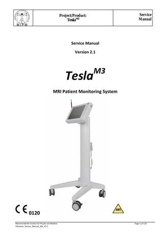
MRI Patient Monitoring System
0120 Mammendorfer Institut für Physik und Medizin Filename: Service_Manual_M3_V2.1
Page 1 of 125
Project/Product: TeslaM3
Service Manual
Content 1.
Introduction ... 5 1.1.
Purpose and Scope ... 5
1.2.
Related Documentation ... 5
1.3.
Symbols/Definitions ... 5
1.4 Safety and essential performance ... 5 2.
3.
4.
5.
Warnings, safety- and installation instructions ... 7 2.1.
Danger of Electrocution... 7
2.2.
Explosion and fire hazard ... 7
2.3.
Equipment Safety and Installation ... 7
2.4.
Safety, Inspection and Maintenance ... 8
System Overview ... 10 3.1.
Indications for Use ... 10
3.2.
System Composition ... 10
3.2.1
General Composition ... 10
3.2.2
MRI Patient Monitor ... 11
3.2.3
Remote Monitor ... 13
3.3.
Patient data management system (PDMS) ... 14
3.4.
System Overview: Block Diagram ... 16
Troubleshooting ... 18 4.1.
Preliminary Diagnostic Procedure ... 18
4.2.
Power-on problems (Master) ... 18
4.3.
Power-on problems (Remote) ... 19
4.4.
General system failure... 19
4.5.
Optical Encoder Malfunction ... 20
4.6.
TFT-Display Malfunction ... 21
4.7.
Alarm Malfunctions ... 21
4.8.
NIBP Malfunction... 21
4.9.
SpO2 Malfunction ... 22
4.10.
ECG Malfunction ... 22
4.11.
IBP Malfunction ... 23
4.12.
etCO2 Malfunction ... 23
4.13.
Temperature Module Malfunction ... 23
Repair procedures ... 25
Mammendorfer Institut für Physik und Medizin Filename: Service_Manual_M3_V2.1
Page 2 of 125
Project/Product: TeslaM3 5.1.
Service Manual
Central Interface Unit (CIU) ... 25
5.1.1
RF module ... 25
5.1.2
IBP socket 1+2... 28
5.1.3
IBP filter 1+2 ... 30
5.1.4
IBP module... 31
5.1.5
IBP DC-DC converter ... 34
5.1.6
Central Interface Board ... 36
5.1.7
Temperature socket 1+2 (cable and socket) ... 38
5.1.8
Temperature module... 41
5.1.9
NIBP module ... 43
5.1.10
NIBP socket ... 45
5.1.11
PO/ECG Gating (socket) ... 47
5.1.12
Capnography module ... 49
5.1.13
Capnography socket ... 52
5.1.14
Battery charging holder for application parts. Axial Lead Fuses F1A ... 54
5.1.15
Power Manager ... 56
5.1.16
Power Supply medical grade ... 58
5.1.17
Power line filters ... 60
5.1.18
M3 Battery ... 62
5.2.
Central Controller Unit/Master (CCU/M) ... 67
5.2.1
CCB Master ... 67
5.2.2
Memory 1 GB ... 71
5.2.3
WLAN Module ... 73
5.2.4
CF Card 8GB ... 74
5.2.5
Cable 13 ... 76
5.2.6
LP-Controller ... 80
5.2.7
Tesla Spy ... 81
5.2.8
On/Off Switch Spy... 83
5.2.9
On/Off Switch ... 85
5.2.10
Optical Encoder ... 86
5.2.11
Encoder Controller C5320 Kit ... 89
5.2.12
USB Interface ... 91
5.2.13
LED Board Spy ... 93
5.2.14
CCU Interface Board ... 94
Mammendorfer Institut für Physik und Medizin Filename: Service_Manual_M3_V2.1
Page 3 of 125
Project/Product: TeslaM3
Service Manual
5.2.15
TFT Display ... 96
5.2.16
Resistive Touch-Screen ... 98
5.3.
Central Controller Unit/Remote (CCU/R) ... 100
5.3.1
Power Supply ... 100
5.3.2
Ethernet Interface ... 102
5.3.3
RS 232 Socket ... 104
5.3.4
AC Inlet Socket ... 106
A.1 Safety Functional Test and Calibration Procedure ... 109 A.2 Safety Functional Test and Calibration Procedure Data Sheet ... 117 APPENDIX B: Wiring Diagrams. Reference Documents (Original): Schematic_TeslaM3_V1 and Schematik_M3_Remote_V1 ... 118 APPENDIX C: Spare Part Catalogue... 120 C.1 Central Interface Unit (CIU) ... 120 C.2 Central Controller Unit/Master (CCU/M) ... 123 C.3 Central Controller Unit/Remote (CCU/R) ... 124
Mammendorfer Institut für Physik und Medizin Filename: Service_Manual_M3_V2.1
Page 4 of 125
Project/Product: TeslaM3
Service Manual
1. Introduction 1.1. Purpose and Scope This manual provides the technically qualified service person with troubleshooting information, repair procedures, and calibration and performance verification instructions. This manual is written for qualified technical service personnel familiar with the operation and design of the Tesla M3 and who have been authorized and trained by MIPM to service the system.
1.2. Related Documentation M3 User Manual
1.3. Symbols/Definitions NOTE: A note presents important information and set it off from the rest of the text.
CAUTION: A caution provides information or instructions that must be followed to ensure proper operation and performance of the equipment.
WARNING: A warning contains important information regarding danger that may result in equipment damage or personal and patient injury.
The indicator refers to a possible action that can be performed by the technician.
1.4 Safety and essential performance The MRI Patient Monitoring System fulfills the applicable general, collateral and particular requirements (standards) for safety and essential performance of Medical Electrical Equipment (IEC 60601-x). Medical Equipment Performance Criteria - unacceptable operating conditions / responses are: - Component failures; - Changes in programmable parameters; - Reset to factory defaults (manufacturer’s presets); - Change of operating mode (adult, children, neonatal, configuration); - False alarms; Mammendorfer Institut für Physik und Medizin Filename: Service_Manual_M3_V2.1
Page 5 of 125
Project/Product: TeslaM3
Service Manual
- Cessation or interruption of any intended operation, even if accompanied by an alarm; - Initiation of any unintended operation, even if accompanied by an alarm; - Error of a displayed numerical value sufficiently large to affect diagnosis or treatment; - Noise on a waveform in which the noise is indistinguishable from physiologically-produced signals or the noise interferes with interpretation of physiologically-produced signals; - Magnet Indicator does perform a reset and measurement is interrupted
Mammendorfer Institut für Physik und Medizin Filename: Service_Manual_M3_V2.1
Page 6 of 125
Project/Product: TeslaM3
Service Manual
2. Warnings, safety- and installation instructions
Warning Observe the following warnings. Failure to comply may result in death, personal injury, and/or equipment damage.
2.1. Danger of Electrocution WARNING: Do not immerse the patient monitor in liquid. This may lead to electrocution. WARNING: Lethal voltages are present. Use extreme care when servicing equipment with the AC/Main power connected. Do not leave an open system unattended with the AC/Main power connected. Disconnect the power cord before removing or replacing components. WARNING: Do not open the patient monitor. CAUTION: Do not utilize this device if known damage exists. Missing, broken, worn or soiled parts must be replaced before application. In the event that repair or part replacement is necessary, please contact your local representative or MIPM, MAMMENDORFER INSTITUT FUER PHYSIK UND MEDIZIN WARNING: Inspect the power cord periodically for fraying or other damage, and replace the cord as needed. Do not operate the apparatus from mains power with a damaged power cord or plug. WARNING: Make frequent electrical and visual checks on cables and electrode wires. WARNING: During defibrillation, keep the discharge paddles away from ECG and other electrodes, as well as other conductive parts in contact with the patient. WARNING: To ensure patient safety, the conductive parts of the ECG electrodes (including associated connectors) and other patient-applied parts should not contact other conductive parts, including earth ground, at any time.
2.2. Explosion and fire hazard WARNING: Do not operate this product in the presence of flammable anesthetics or other flammable substance in combination with air, oxygen-enriched environments, or nitrous oxide; explosion can result.
2.3. Equipment Safety and Installation WARNING: Autoclave accessories only if the manufacturer's instructions clearly approve it. Many accessories can be severely damaged by autoclaving. WARNING: Only connect the Tesla M3 to electrical sources of the proper voltage and frequency. Mammendorfer Institut für Physik und Medizin Filename: Service_Manual_M3_V2.1
Page 7 of 125
Project/Product: TeslaM3
Service Manual
WARNING: The Tesla M3 contains electrostatic sensitive components. You must wear a wrist grounding strap when handling components and place on an anti-static pad. Failure to comply may result in damage to equipment due to electrostatic discharge. Please note that for safety reasons the unit should not be connected to mains. WARNING: Do not open the device unless instructed to do so in this manual. WARNING: The device may be operated at a maximum magnetic field strength of 20mT / 200G. Depending on the different scanners this means a distance of approximately 1.5m / 5ft to the opening of the bore (based on actively shielded 3T scanner).
2.4. Safety, Inspection and Maintenance WARNING: Because of the danger of electric shock, never remove the cover of any device while in operation or connected to a power outlet. CAUTION: A regular servicing (every 12 Months) is recommended, nevertheless, the legal demands must be kept at least. CAUTION: A function test must be performed before each application of this device. WARNING: This monitor should only be repaired by qualified service personnel who have been authorized and trained to service the system. The operator should not attempt to open the monitor case or perform any maintenance on the monitor except for procedures explicitly described in this manual that can be performed by operators such as inspection and cleaning. CAUTION: To preserve the life of the internal battery, always leave the monitor connected to main power when not in use. Mammendorfer Institut für Physik und Medizin Filename: Service_Manual_M3_V2.1
Page 8 of 125
Project/Product: TeslaM3
Service Manual
The user of this device is solely responsible for any failure of the device to perform properly due to unauthorized and incorrect maintenance, incomplete repair, or damage and changes made by unauthorized personnel. CAUTION: Do not open device, since this will violate the shielding screen. After opening an inspection must be performed by authorized service personnel.
2.5 Summary of Safety Notices This Safety Summary should be read by all Tesla M3 monitor users. Specific warnings and cautions are placed throughout the documentation where they apply.
WARNING: This monitor is to be operated by qualified personnel only. The operator of this monitor should read the Tesla M3 User Manual. WARNING: To ensure patient safety, use only accessories recommended or supplied by MIPM. For a list of those accessories, see Tesla M3 User Manual. Accessories must be used according to your hospital’s standards and the manufacturer’s recommendations. Always refer to the manufacturer’s directions for use. WARNING: A product that has been dropped or severely abused should be checked by qualified service personnel to verify proper operation and acceptable risk (leakage) current values. WARNING: The Tesla M3 should be serviced only by MIPM service technicians while under warranty. CAUTION: All reusable components of the device must be cleaned and sterilized. All disposable components must be replaced before using the system on another patient. CAUTION: Use only genuine replacement parts manufactured or released by MIPM. Use of parts furnished by other sources may result a danger or failure and will void any warranty.
Mammendorfer Institut für Physik und Medizin Filename: Service_Manual_M3_V2.1
Page 9 of 125
Service Manual
Project/Product: TeslaM3 3. System Overview 3.1. Indications for Use
The MRI Patient Monitoring System Tesla M3 is intended for monitoring of vital signs during MRI examinations (MRI procedures) of patients. The Tesla M3 is capable for continuous monitoring of Electrocardiogram (ECG), Pulse Oximetry (SpO2), NonInvasive Blood Pressure (NIBP), Invasive Blood Pressure (IBP), Temperature, Respiration, Capnography (etCO2), Oxygen and Anesthetic Agents. The Tesla M3 is intended for use by health care professionals. Prescription: In the USA, federal law restricts this device to sale by or on the order of a physician.
Contraindication: The device is not designed to be used outdoors, in homecare, ambulances, helicopters, aircraft, submarines, boats, hyperbaric chambers, explosive or flammable environment.
3.2. System Composition 3.2.1
General Composition
The MRI Patient Monitoring System Tesla M3 consists of the following devices:
A) MRI Patient Monitor with applied parts / accessories (Position: MR Environment / MRI Room) B) Remote Monitor (Position: MRI Control Room) with wireless Data Transceiver Unit (DTU) from MR Environment to MRI Control Room
The System is designed in a basic configuration (ECG, Pulse Oximetry, NIBP) and the additional options can be configured (and upgraded) according to individual customer needs.
Mammendorfer Institut für Physik und Medizin Filename: Service_Manual_M3_V2.1
Page 10 of 125
Service Manual
Project/Product: TeslaM3 Table of Variants: Products / Modules A) MRI Patient Monitor
Configuration 1) Basic Configuration
MIPM REF 1800001
Remark Main and Battery Powered
Option Option Option Option
5200057 5200058 5400037 5400038
Display-Unit with Touchscreen and optical encoder to operate Graphical User Interface Patient interface unit and Power Management Module with wireless ECG Sensor (ECGAP1) and Accessories Module with wireless Pulse Oximetry Sensor (POAP2) and Accessories Module and Accessories Module and Accessories Module and Accessories Module and Accessories Module and Accessories
Option Option Option Option
5800001 5800002 5450014 5450012
Module and Accessories Module and Accessories Module and Accessories Main Powered
Central Controller Unit / Master (CCU/M) Central Interface Unit (CIU) ECG Pulse Oximetry NIBP IBP 1 IBP 2 Capnography Multigas: Capnography, Oxygen and Anesthetic Agents (Auto Detection) Temperature 1 Temperature 2 Gating B) Remote Monitor2) incl. Data Transceiver Unit Central Controller Unit / Remote (CCU/R) Data Transceiver Unit (DTU)
Display-Unit with Touchscreen and optical encoder to operate Graphical User Interface Wireless Data Transceiver Unit from CCU/M in MR Environment to CCU/R in MR Control Room
1)
Not installed parameters are suppressed (hardware switch) in Graphical User Interface (GUI). The optional Remote Monitor in the MRI Control room has generally the same functionality (Graphical User Interface) as the MRI Patient Monitor in the MR Environment. 2)
3.2.2
MRI Patient Monitor
A) MRI Patient Monitor (CCU/M and CIU) with applied parts / accessories Intended Conditions of use in the MR Environment: The device is MR Conditional with intended conditions of use in the MR Environment MR Scanner: max. 3.0 Tesla max. Magnetic Field: 20mT/200 Gauss (this is equivalent to a distance of approx.1.5m by a 3.0 Tesla MR Scanner). The mechanical construction (faraday cage of antimagnetic materials), certain shielding and filtering technologies guarantee interference free operating in the MR Environment without any interferences on the device itself and also for the MR Scanner. Patients: The device is intended for use in the Adult, Pediatric and Neonatal populations. The MRI Patient Monitor consists of two main assemblies: Central Controller Unit / Master (CCU/M) The CCU/M is operating as control and display unit and consisting of the Central Controller Board (CCB), Display with Touchscreen, Optical Encoder, ON/OFF Switch, Tesla Spy 2010 (Magnet Indicator), Speaker and two USB-Interfaces. Mammendorfer Institut für Physik und Medizin Filename: Service_Manual_M3_V2.1
Page 11 of 125
Service Manual
Project/Product: TeslaM3
Central Interface Unit (CIU) The CIU is operating as a data collector (interface unit to the patient) and supplies the integrated modules and the CCU/M with power (AC or battery power).
Component Housing of CCU/M: Housing of CIU:
Material mainly coated aluminium, Color: RAL 9016 (traffic white) and RAL 5015 (sky blue) for markings; antimagnetic stainless steel, plastics mainly coated aluminium , Color: RAL 9016 (traffic white) and RAL 5015 (sky blue) for markings; antimagnetic stainless steel, plastics
Display: Colored graphical display Display of waveforms and numerics User interface: ON/OFF switch Touchscreen to operate Graphical User Interface (GUI) Optical Encoder to operate Graphical User Interface (GUI) Remark: The additional optical encoder is a result from risk analysis (risk mitigation) regarding a malfunction of the touchscreen. Alarms: Physiological Alarms and Technical Information’s Visual and Auditory Signals Preset upper and lower Alarm limits
Monitoring of vital signs parameter: Parameter / Module
Measured and Displayed Vital Signs Parameter
ECG Pulse Oximetry NIBP IBP (1 or 2) Capnography
Heart Rate (HR) Oxygen Saturation (SpO2), Pulse Rate (PR) Systolic (Sys), Diastolic (Dia) and Mean Blood Pressure (MAP) Systolic (Sys), Diastolic (Dia) and Mean Blood Pressure (MAP) end tidal and inspiratory Carbon Dioxide (etCO2; iCO2), Respiration Rate (RR) end tidal and inspiratory Carbon Dioxide (etCO2; iCO2) Respiration Rate (RR); end tidal and inspiratory concentration of Oxygen (O 2), Nitrous Oxide (N2O), Halothane (HAL), Isoflurane (ISO), Enflurane (ENF), Sevoflurane (SEV), Desflurane (DES) Body Temperature
Gases1): Capnography, Oxygen and Anesthetic Agents (Auto Detection) Temperature (1 or 2)
Waveform and/ or Numeric Waveform and Numeric Waveform and Numeric Numeric Waveform and Numeric Waveform and Numeric Waveform and Numeric
Numeric
Gating / Triggering of external devices (e.g. MR Scanners from Siemens): ECG (Maximum of R-Wave) Pulse Oximetry (Maximum of Pulse-Wave)
Data Management: Trend memory Event memory Patient data Interfaces for Data Output of Trend/Event: USB for pen drive USB for printer Mammendorfer Institut für Physik und Medizin Filename: Service_Manual_M3_V2.1
Page 12 of 125
Service Manual
Project/Product: TeslaM3 PDMS Interfaces: No interface to PDMS on MRI Patient Monitor Power Management: Main Power Supply Battery Power Supply Charging of internal Battery Charging of batteries from wireless Pulse Oximetry Sensor and wireless ECG-Sensor Magnet Indicator / Tesla Spy (TSpy2010): Magnet Indicator to position MRI Patient Monitor in the MR Environment Measurement and Indication of Magnetic Field Visual and Auditory Signal for critical and unacceptable Magnetic Fields
3.2.3
Remote Monitor
B) Remote Monitor (CCU/R) with Data Transceiver Unit (DTU) The optional wireless Remote Monitor is not intended to be used in the MR Environment (MR Unsafe) and has no contact to the patient. The Remote Monitor (CCU/R) in the MR Control room has the same functionality (Graphical User Interface) as the MRI Patient Monitor (CCU/M and CIU) in the MR Environment. The Remote Monitor displays the same vital signs parameter and alarms as installed in the MRI Patient Monitor. A further feature is the possibility to connect the Remote Monitor to a PDMSSystem (Patient Data Management System) via RS 232 or Ethernet. The wireless Data Transceiver Unit (DTU) is transmitting data from MRI Patient Monitor (CCU/M) in the MR Environment to the Remote Monitor (CCU/R) in the MR Control Room and vice versa. (MRI Patient Monitor has priority by inputs from operators at the same time on MRI Patient Monitor and Remote Monitor). The Remote Monitor is consisting of the Central Controller Board (CCB), Display with Touchscreen, Optical Encoder, ON/OFF Switch, Speaker, two USB-Interfaces, RS 232 Interface, Ethernet Interface and an integrated Main Power Supply (AC Power). Component Housing of CCU/R:
Material mainly coated aluminium, Color: RAL 9016 (traffic white) and RAL 5015 (sky blue) for markings; antimagnetic stainless steel, plastics
Display: Colored graphical display Display of waveforms and numerics User interface: ON/OFF switch Touchscreen to operate Graphical User Interface (GUI) Optical Encoder to operate Graphical User Interface (GUI) Remark: The additional optical encoder is a result from risk analysis (risk mitigation) regarding a malfunction of the touchscreen.
Monitoring of vital signs parameter and Alarms
Remote display of the same vital signs parameters and alarms as installed in the MRI Patient Monitor Indication of connection from MRI Patient Monitor to Remote Monitor
Mammendorfer Institut für Physik und Medizin Filename: Service_Manual_M3_V2.1
Page 13 of 125
Project/Product: TeslaM3
Service Manual
Gating / Triggering of external devices (e.g. MR Scanners from Siemens): No interface for Gating on Remote Monitor Data Management: Trend memory Event memory Patient data Interfaces for Data Output of Trend/Event: USB for pen drive USB for printer PDMS Interfaces: Ethernet/LAN for Patient Data Management System RS232 for Patient Data Management System Power Management: Main Power Supply
3.3. Patient data management system (PDMS) There are 2 options to transmit data from the system to a PDMS: 1.
2.
3.
RS232 a. b.
Format: .txt Settings: i. BaudRate: 9600; Data: 8; Stop: 1; Parity: None
Ethernet: a. The transfer of a PDMS data via Ethernet is occurred by generating an XML file with the equivalent content of the transmitted data via RS232 and transfer to the PDMS server based on Secure Copy - scp Secure with Shell - SSH authentication. b.
The PDMS Server must have the functionality of SSH Server – Secure Shell Server. The copy function is implemented in an external script to make the transfer flexibly adaptable. The default configuration Provides that a defined user (Username: mipmmms, Passwort mipmmmspdms) is configured on the server. The transferred PDMS file is in home directory of this user (/home/mipmmms/YYYYMMDDHHMMSSpdmsxml.txt).
c.
After successful establishment of the PDMS-Ethernet transfer the PDMS-files are stored continuously in 10second intervals in the home directory of the user mipmmms on the PDMS server: /home/mipmmms/YYYYMMDDHHMMSSpdmsxml.txt. YYYYMMDD contains the current date and HHMMSS the current time according to the field contents of the file PDMS.
Protocol for the RS232 and Ethernet output
Data are transmitted via the configured RS232 interface in the service menu every 10 s in string format. The mean values must be transmitted.
The data are transmitted connectionless to the PDMS servicer. There is no error handling. Mammendorfer Institut für Physik und Medizin Filename: Service_Manual_M3_V2.1
Page 14 of 125
Project/Product: TeslaM3
Service Manual
If a value is not available placeholder is filled with ---
String format ( ASCII Code): PIDXXXXXXXXXX
Patient ID
LNXXXXXXXXXX
Last Name
FNXXXXXXXXXX
First Name
PCXXXXXXXXXX
Patient Category
DBXXXXXXXX Date of Birth GDXXXXXX
yyyymmdd
Gender
HXXX
Height (cm e.g. 173 for 1.73m)
WXXX
Weight (kg e.g. -67 for 67kg)
HRXXX
Heart Rate (bpm)
PRXXX
Pulse Rate (bpm)
SOXXX
Saturation (%)
NSXXX
NIBP Systolic Pressure (mmHg)
NDXXX
NIBP Diastolic Pressure (mmHg)
NMXXX
NIBP Mean Pressure (mmHg)
I1SXXX
Invasive Systolic Pressure 1 (mmHg)
I1DXXX
Invasive Diastolic Pressure 1 (mmHg)
I1MXXX
Invasive Mean Pressure 1 (mmHg)
I2SXXX
Invasive Systolic Pressure 2 (mmHg)
I2DXXX
Invasive Diastolic Pressure 2 (mmHg)
I2MXXX
Invasive Mean Pressure 2 (mmHg)
ETXXX iXXX
etCO2 (dependent on configuration % by vol. or mmHg) iCo2 (dependent on configuration % by vol. or mmHg)
RRXXX
Respiration Rate
T1XXX
Temperature 1 (°C)
T2XXX
Temperature 2 (°C)
AAiOXXX
Anaesthetic Agent iO2 (% by vol.)
AAiNXXX
Anaesthetic Agent iN2O (% by vol.)
AAiAXXX
Anaesthetic Agent i (Last A is for appropriate Agent) (% by vol.)
AAeOXXX
Anaesthetic Agent eiO2 (% by vol.)
AAeNXXX
Anaesthetic Agent eN2O (% by vol.)
AAeAXXX
Anaesthetic Agent e (Last A is for appropriate Agent) (% by vol.)
Abbreviations: X = Placeholder for values, DT = Date and Time Format e.g. 201008180745 Mammendorfer Institut für Physik und Medizin Filename: Service_Manual_M3_V2.1
Page 15 of 125
Project/Product: TeslaM3
Service Manual
-> Year=2010; Month=August;Day=18;Hour=7;Minute=45
Anaesthetic Agents: Halothane = H Enflurane = E Isoflurane = I Sevoflurane = S Desflurane = D
3.4. System Overview: Block Diagram
Mammendorfer Institut für Physik und Medizin Filename: Service_Manual_M3_V2.1
Page 16 of 125
Project/Product: TeslaM3 System Overview (Copy):
Service Manual
Reference Document (Original): BlockDia_M3_V1
Mammendorfer Institut für Physik und Medizin Filename: Service_Manual_M3_V2.1
Page 17 of 125
Service Manual Tesla M3
4.
Troubleshooting
DO NOT OPEN OR REMOVE THE TESLA M3 UNLESS YOU MUST ACCESS INTERNAL COMPONENTS AS INSTRUCTED IN THIS MANUAL. Once the Tesla M3 has been opened, the unit must undergo Safety Functional Test and Calibration Procedure (see Appendix A). The appropriate tests must be performed before the unit can be returned for use.
4.1. Preliminary Diagnostic Procedure There may be times when the system is suspected of a malfunction when, in fact, it is fully operational. This can be the result of human error, failure of other equipment, poor connections, and so on. Always follow the common sense procedures presented below before attempting any lengthy diagnostics or repair actions. It will save time and avoid needlessly taking the system apart. 1. Inspect the AC/Main power cord for possible damage. 2. Test the outlet for proper voltages. 3. Ensure that the AC/Main power cord is securely plugged into an electrical outlet and into the back of the unit. 4. Inspect Line Fuses in Fuse Holder. If either fuse has failed, replace. If fuses continue to fail, perform further diagnostics. 5. Make several attempts to recreate the problem including applying and removing power a number of times. If the problem does not reoccur, perform Safety Functional Test and Calibration Procedure (see Appendix A). If system passes all tests, return the system for use. If result of Section 4.1 – Preliminary Diagnostic Procedure, does not solve the problem, proceed to detailed troubleshooting described below.
4.2. Power-on problems (Master) Table 1 Problem Monitor connected
Potential cause Power circuitry multifunction
Potential involved parts and suggested actions -“Power Supply medical grade”
directly to AC; Battery
-“Power Manager”
Charger LED of “On/Off Switch” not illuminated
-“CCU Interface Board” -“On/Off switch” Refer to section 5 “Repair procedures” and appendix B “Wiring diagrams”. Contact MIPM, or your local distributor for service.
M3
Tesla monitor does not power on in battery mode
Battery or Battery charger circuitry malfunction
-“M3 Battery” -“ Power Manager” Refer to section 5 “Repair procedures” and appendix B “Wiring diagrams”.
Mammendorfer Institut für Physik und Medizin Filename: Service_Manual_M3_V2.1
Page 18 of 125
Service Manual Tesla M3
Contact MIPM or your local distributor for service. Power cord is connected but the battery indicator
Battery charger circuitry malfunctions
-“Power Supply medical grade” -“Power Manager”
is not shown Refer to section 5 “Repair procedures” and appendix B “Wiring diagrams”. Contact MIPM, or your local distributor for service. System failure
Contact MIPM, or your local distributor for service.
4.3. Power-on problems (Remote) Table 2 Problem
Potential cause
Potential involved parts and suggested actions -“CCU Interface Board” -“On/Off switch”
Power circuitry multifunction Power cord is connected but the monitor cannot be turned on
-“Power Supply” Refer to section 5 “Repair procedures” and appendix B “Wiring diagrams”. Contact MIPM, or your local distributor for service.
4.4. General system failure Table 3 Problem
Potential cause
Potential involved parts and suggested actions -“Resistive Touch-Screen” -“CCB” -“CF Card 8GB”
M3
No response from Tesla Monitors when icons are pressed.
Touch screen failure
Refer to section 5 “Repair procedures” and appendix B “Wiring diagrams”. Contact MIPM, or your local distributor for service.
Mammendorfer Institut für Physik und Medizin Filename: Service_Manual_M3_V2.1
Page 19 of 125
Service Manual Tesla M3
System failure
If situation recurs after restart of the monitor contact MIPM or service. -“CCB”
System failure
-“CCU Interface board” -“Tesla Spy”
Continuous speaker sound
Refer to section 5 “Repair procedures” and appendix B “Wiring diagrams”. Contact MIPM, or your local distributor for service. -“Central Interface Board” System failure
-No Power at “Central Interface Board” -Cables
“No communication with CIB”
Refer to section 5 “Repair procedures” and appendix B “Wiring diagrams”. Contact MIPM, or your local distributor for service. Check the WLAN system e.g. using a laptop.
“No communication with master”
System failure
Restore Default Settings. Contact MIPM, or your local distributor for service. -“CF Card 8GB” -“ CCB”
System failure System booting (start) not possible
Refer to section 5 “Repair procedures” and appendix B “Wiring diagrams”. Contact MIPM, or your local distributor for service.
4.5. Optical Encoder Malfunction Table 4 Problem
Potential cause
Rotary knob fails to properly select fields, or pressing the knob in fails
Optical Encoder malfunction
Refer to section 5 “Repair procedures” and appendix B “Wiring diagrams”.
Encoder Controller C5320 Kit
Contact MIPM, or your local distributor for
Mammendorfer Institut für Physik und Medizin Filename: Service_Manual_M3_V2.1
Suggested actions
Page 20 of 125