Medical Measurement Systems
Solar Service & Installation Manual Aug 2005
Service & Installation Manual
128 Pages
Preview
Page 1
Service & Installation Manual FOR MEASUREMENT SYSTEM
Solar WITH SOFTWARE VERSION 8 For Windows 2000 / XP 1) Enschede Manual version August 2005
Medical Measurement Systems PO Box 580 7500 AN Enschede The Netherlands Phone : +31 - 53 480 37 00 Fax : +31 - 53 480 37 01 E-mail : [email protected] Internet : www.mmsinternational.com
1) Windows 2000 and XP are trademarks of Microsoft Corporation, USA.
Solar service © 2001-2005 by MMS b.v.
MMS (head office) P.O.Box 580 7500 AN Enschede The Netherlands Tel : +31-53-480 37 00 Fax : +31-53-480 37 01 Email : [email protected] MMS Deutschland GmbH Postfach 10 10 27 D-46210 Bottrop Deutschland Tel : 0 20 41 - 55 80 10 Fax : 0 20 41 - 55 80 11 Email : [email protected] MMS USA, Inc. 100 Main Street, Suite 111 Dover, NH 03820 USA Tel : 800 - 236-9310 Tel : 603 - 750-0037 Fax : 603 - 750-3155 Email : [email protected] MMS document code: 0075-MAN-005-03V00E Solar Service & Installation Manual MMS is a registered trademark of Medical Measurement Systems B.V., Enschede, the Netherlands. Solar service © 2001-2005 by MMS b.v.
Table of contents
Table of Contents
Table of contents
3.2 3.3
Safety information Solar 1 Solar measurement system... 1-1 1.1 Introduction... 1-1 1.2 MMS software program... 1-3 1.3 Solar modules... 1-4 1.4 Solar configurations... 1-6 1.4.1 Introduction... 1-6 1.4.2 Solar Urodynamic system... 1-6 1.4.3 Solar GI system... 1-8 1.4.4 Solar Neuro system... 1-10 1.5 Block diagram... 1-11 1.6 Diagnostic program... 1-12 1.7 Trouble shooting... 1-12 1.8 Repair... 1-13 1.9 Warranty... 1-13 1.10 Manuals and on-line help... 1-14 2 Installation... 2-1 2.1 Introduction... 2-1 2.2 Solar trolley... 2-2 2.2.1 Silver and Gold trolleys... 2-2 2.2.2 Safety information... 2-3 2.2.3 Installation procedure... 2-3 2.2.4 Trolley accessories... 2-5 2.3 Solar infusion pole... 2-6 2.3.1 Components pole... 2-6 2.3.2 Safety information... 2-7 2.3.3 Installation procedure... 2-8 2.4 Solar Maquet investigation chair... 2-10 2.4.1 Components for Maquet chair... 2-10 2.4.2 Safety information... 2-10 2.4.3 Installation procedure... 2-11 2.5 Test the installation... 2-14 3 Computer... 3-1 3.1 Introduction... 3-1 Solar service © 2001-2005 by MMS b.v.
3.4 3.5
Safety information... 3-1 Installation... 3-2 3.3.1 Install the MMS software (without Bluetooth) . . . 3-2 3.3.2 Install the MMS software (with Bluetooth)... 3-3 3.3.3 Install the USB key... 3-4 3.3.4 Install the computer... 3-4 Diagnostic program... 3-5 Trouble shooting... 3-6
4 Solar Safety Module (SSM)... 4-1 4.1 Introduction... 4-1 4.2 Safety information... 4-1 4.3 Installation... 4-2 4.4 Block diagram... 4-8 4.5 Diagnostic program... 4-9 4.6 Trouble shooting... 4-9 4.7 Replace fuses... 4-10 5 Solar Main Module (SMM)... 5-1 5.1 Introduction... 5-1 5.2 Safety information... 5-1 5.3 Installation... 5-2 5.4 Block diagram... 5-4 5.5 Diagnostic program... 5-5 5.6 Trouble shooting... 5-7 5.7 Replace fuses... 5-8 6 Solar U2M Module (U2M)... 6-1 6.1 Introduction... 6-1 6.2 Safety information... 6-2 6.3 Installation... 6-3 6.4 Block diagram... 6-5 6.5 Diagnostic program... 6-7 6.6 Trouble shooting... 6-9 7 Solar Infrared Receiver (SIR)... 7-1 7.1 Introduction... 7-1 7.2 Safety information... 7-1 7.3 Installation... 7-1 7.4 Block diagram... 7-2 Solar service © 2001-2005 by MMS b.v.
Table of contents
7.5 7.6
Diagnostic program... 7-2 Trouble shooting... 7-2
8 Remote control... 8-1 8.1 Introduction... 8-1 8.2 Safety information... 8-1 8.3 Installation... 8-2 8.4 Diagnostic program... 8-3 8.5 Trouble shooting... 8-4 9 Pump Infused volume Module (PIM)... 9-1 9.1 Introduction... 9-1 9.2 Safety information... 9-2 9.3 Installation PIM... 9-4 9.4 Installation pump tube... 9-5 9.4.1 Silver pump... 9-5 9.4.2 Gold pump... 9-6 9.4.4 Flush button for pump filling tube... 9-9 9.4.5 Abort button... 9-9 9.5 Block diagram... 9-10 9.6 Diagnostic program... 9-11 9.7 Trouble shooting... 9-14 9.8 Disassemble Gold pump head... 9-17 10 Combination Interface Module (CIM)... 10-1 10.1 Introduction... 10-1 10.2 Safety information... 10-1 10.3 Installation... 10-2 10.4 Block diagram... 10-5 10.5 Diagnostic program... 10-6 10.6 Trouble shooting... 10-9 11 H2O Transducer Interface (HTI)... 11-1 11.1 Introduction... 11-1 11.2 Safety information... 11-1 11.3 Installation... 11-2 11.4 Block diagram... 11-4 11.5 Diagnostic program... 11-5 11.6 Trouble shooting... 11-7
Solar service © 2001-2005 by MMS b.v.
Table of contents
12 MicroTip Catheter interface (MTC)... 12-1 12.1 Introduction... 12-1 12.2 Safety information... 12-1 12.3 Installation... 12-2 12.4 Block diagram... 12-4 12.5 Diagnostic program... 12-5 12.6 Trouble shooting... 12-7 13 Digital EMG Module (DEM)... 13-1 13.1 Introduction... 13-1 13.2 Safety information... 13-1 13.3 Installation... 13-1 13.4 Block diagram... 13-3 13.5 Diagnostic program... 13-4 13.6 Trouble shooting... 13-5 14 Solar Neuro Module (SNM)... 14-1 14.1 Introduction... 14-1 14.2 Safety information... 14-1 14.3 Installation... 14-3 14.4 Front side... 14-4 14.5 Block diagram... 14-5 14.6 Diagnostic program... 14-7 14.7 Trouble shooting... 14-9 15 Flowmeter Mk III (FLM)... 15-1 15.1 Introduction... 15-1 15.2 Safety information... 15-2 15.3 Installation... 15-3 15.3.1 Install the flowmeter... 15-3 15.3.2 Register Bluetooth flowmeter... 15-5 15.4 Block diagram... 15-7 15.5 Diagnostic program... 15-9 15.6 Trouble shooting... 15-10 16 Digital Plugin Flow sensor (DPF) - Flowmeter Mk II... 16-1 16.1 Introduction... 16-1 16.2 Safety information... 16-1 16.3 Installation... 16-2 16.4 Block diagram... 16-3 Solar service © 2001-2005 by MMS b.v.
Table of contents
16.5 Diagnostic program... 16-4 16.6 Trouble shooting... 16-6 17 Solar Catheter Puller (SCP)... 17-1 17.1 Introduction... 17-1 17.2 Safety information... 17-1 17.3 Installation... 17-2 17.4 Block diagram... 17-4 17.5 Diagnostic program... 17-5 17.6 Trouble shooting... 17-7 18 Solar CO2 Module (SCM)... 18-1 18.1 Introduction... 18-1 18.2 Safety information... 18-1 18.3 Installation... 18-3 18.3.1 Installation CO2 module... 18-3 18.3.2 Installation pressure transducer... 18-5 18.4 Block diagram... 18-7 18.5 Diagnostic program... 18-9 18.6 Trouble shooting... 18-10 18.7 Preventive maintenance... 18-10 19 CIM-AUX module... 19-1 19.1 Introduction... 19-1 19.2 Safety information... 19-1 19.3 Installation... 19-2 19.4 Block diagram... 19-4 19.5 Trouble shooting... 19-6 20 Diagnostic program... 20-1 20.1 Introduction... 20-1 20.2 Start the diagnostic program... 20-1 20.3 USB information... 20-3 20.4 System information... 20-4 20.4.1 Solar... 20-5 20.4.2 Computer... 20-5 20.4.3 Environment... 20-7 20.4.4 Processes... 20-7 20.4.5 Program versions... 20-7 20.4.6 System files... 20-7 Solar service © 2001-2005 by MMS b.v.
Table of contents
20.4.7 Disk usage... 20-7 20.4.8 Printers... 20-8 20.4.9 USB... 20-8 20.4.10 Print and save System information... 20-8 20.5 Download software... 20-9 20.5.1 System upgrade... 20-9 20.5.2 Download software via module... 20-9 20.5.3 Download software via menu... 20-10 20.6 Test pressure transducers and catheters... 20-11 20.6.1 Introduction... 20-11 20.6.2 Test pressure transducers... 20-11 20.6.3 Test catheter... 20-12 20.7 Pressure transducer calibration... 20-14 20.7.1 When to calibrate pressure transducers? . . . 20-14 20.7.2 Calibrate one transducer... 20-15 20.7.3 Calibrate a catheter... 20-16 20.7.4 Calibration settings... 20-17 20.7.5 Calibration procedure... 20-18 20.7.6 Reset calibration... 20-19 21 Maintenance... 21-1 21.1 Introduction... 21-1 21.2 Preventive maintenance... 21-1 21.3 Cleaning the system... 21-4 21.4 Backup patient data... 21-6 22 Technical specifications... 22-1 22.1 General... 22-1 22.2 Solar trolley... 22-1 22.3 Solar infusion pole... 22-2 22.4 Solar Maquet chair... 22-2 22.5 Computer requirements... 22-2 22.6 Solar Safety module... 22-3 22.7 Solar Main module... 22-3 22.8 Solar U2M module... 22-3 22.9 Solar Infrared receiver... 22-4 22.10 Remote control... 22-4 22.11 Pump infused volume module... 22-4 22.12 Combination interface module... 22-5 22.13 H2O transducer interface... 22-7 Solar service © 2001-2005 by MMS b.v.
Table of contents
22.14 Microtip catheter interface... 22-8 22.15 Digital EMG module... 22-9 22.16 Solar Neuro module... 22-9 22.17 Flowmeter Mk III... 22-11 22.18 Digital plugin Flow sensor - Flowmeter Mk II... 22-12 22.19 Solar Catheter puller... 22-13 22.20 Solar CO2 module... 22-13 22.21 CIM-AUX module... 22-13 Index Warranty Appendix A Appendix B Appendix C Appendix D Appendix E
Cables Explanation of symbols Safety barriers Solar trolley Repair information report CE certificate / Declaration of conformity
Safety information
Safety information Solar Before working with the Solar measurement system and its manuals, you have to know the general safety information as described in this chapter. Refer to the chapters of the connected Solar modules for device specific safety information. This sign is printed in this manual in front of important warnings. It is important to pay good attention to these warnings to provide patient safety and to prevent damaging of the equipment. The Solar is a prescription device to be used only by physicians or individuals who have been trained and authorized by a physician or by a medical institution, under the supervision of a physician. The Solar must be purchased under the supervision of a physician. For US only: Caution: Federal law restricts this device to sale by or on the order of a physician. The Solar is designed in accordance with IEC Publication 60601-1 (Medical Electrical Equipment). The Solar is CE (93/42/EEC) approved. The Solar only conforms to the MDD (Medical Device Directive) when it is used with CE approved MMS modules/devices. The instructions and warnings in this manual should be followed by the operator to ensure safe operation and to maintain the Solar in a safe condition. Therefore the use of the Solar should be restricted to qualified personnel only. The Solar can only be used indoor at temperatures between +15EC and +35EC (+59EF to +95EF) and at a humidity between 45% and 75%, noncondensing. The Solar, the computer and the other devices must be used or stored in a dust-free environment. All repairs, which are performed by the hospital personnel are for the responsibility of the hospital. MMS will not give any guarantee on a part, which has been opened, adjusted or replaced by hospital personnel. The Solar may only be opened for any adjustment, replacement, maintenance or repair by MMS qualified personnel.
Solar service © 2001-2005 by MMS b.v.
Solar service © 2001-2005 by MMS b.v.
Safety information
Unpacking WARNING
Refer to the packing list to check if all items are present.
WARNING
Please be careful while unpacking the system. The Solar consists of delicate equipment.
Safety information
WARNING
Make sure that when the patient is connected to more than one apparatus, the leakage currents will not exceed the allowed limits. Take note of IEC 60601-1-1.
WARNING
The digital cables connected to the Solar modules all have a connector with locking mechanism. Do not attempt disconnection by pulling the cable. Loosen the lock by pressing the lever on the connector.
Installation WARNING
Connect only MMS devices to the Solar (except the computer and the catheters).
WARNING
Safety can be violated if the Solar or one of its modules shows visible damage.
WARNING
Do not attempt to open Solar modules.
WARNING
MMS advises to provide all mains powered equipment with a connected equipotential wire.
WARNING
If a safe system setup according to the IEC-60601 can not be guaranteed, a Safety module is required. Please contact MMS.
WARNING
If the computer is connected to external devices (such as printer, modem, telephone-lines, sound systems, network, video sources, display systems) and/or the MMS equipment is combined with other equipment (for example Barostat or TMPD) make sure that the following requirements are met. IEC 60601-1 (Medical electrical equipment, Part 1: General requirements for safety) and/or IEC 60601-1-1 (Medical electrical equipment, Part 1: General requirements for safety, 1.Collateral standard: Safety requirements for medical electrical systems).
Solar service © 2001-2005 by MMS b.v.
Catheters and accessories WARNING
Use only disinfected or sterile catheters.
WARNING
Always check the expiry date of sterile goods.
WARNING
To prevent drift, always pre-wet microtip catheters (sensors) according to the instruction of the manufacturer.
Cleaning WARNING
Never use any detergents, thinner, benzine or other volatile chemicals while cleaning the Solar measurement system.
WARNING
Do not use excessive amounts of water for cleaning the Solar.
WARNING
Never allow water to get inside the Solar modules or any other part.
WARNING
Never apply any force on the flow sensor during cleaning.
Solar service © 2001-2005 by MMS b.v.
Safety information
Repair (MMS qualified personnel only) WARNING
Before repair always take antistatic precautions.
WARNING
Be sure to perform a safety test according to IEC 60601-1 after modules/devices have been replaced or opened.
WARNING
Before repair make sure that the Solar system is switched off and disconnected from the mains.
Investigations WARNING
Investigation procedures as described in the Solar manuals do not pretend to be complete. How an investigation is performed and how the results are interpreted remains under all circumstances the responsibility of the clinician performing the investigation. The description of investigation proceedings is only included to serve as an example to discuss the use of the various markers and the various transducers.
WARNING
Never turn off the Solar system if Windows is still active. You may loose data.
WARNING
Automatic safeguards built into the software should be seen as an aid. They are not substitutes for careful personal monitoring and an alert investigator.
Solar service © 2001-2005 by MMS b.v.
Safety information
WARNING
Safety can be violated if, for example, the apparatus: ! shows visible damage. ! fails to perform the intended measurement. ! has been subjected to prolonged storage under unfavourable conditions. ! has been subjected to severe stresses in transit. ! has been handled by unqualified personnel.
Although precautions have been taken in this apparatus to prevent malfunctions due to abnormal environmental conditions and/or abnormal handling, such malfunctions can occur in some circumstances. Abnormal environmental conditions include, but are not limited to: ! any other condition as is specified in the manual. ! (electro-)magnetic fields caused by portable equipment (as telephones, computers), X-ray equipment, (radio-)transmitters, radar-equipment, etcetera. ! Electro Static Discharge. ! mains disturbances. ! extreme temperatures, pressures, humidity, dust, etcetera. Abnormal handling includes, but is not limited to: ! any handling other than specified in the manual. ! rough handling. ! handling by unqualified staff. Provided such or similar conditions do not occur, this apparatus will prove to be durable and reliable. NOTE
Check the Solar measurement system regularly with the diagnostic program.
NOTE
For cleaning of the catheters, we refer to the manufacturer’s instructions.
Solar service © 2001-2005 by MMS b.v.
Solar measurement system
1 Solar measurement system 1.1 Introduction The Solar measurement system is developed by Medical Measurement Systems (MMS) to perform urodynamic and/or gastro-Intestinal (GI) investigations in hospitals and private clinics.
Solar measurement system
Modular setup The Solar is a digital plug-and-play system offering a modular and flexible setup. This allows the user to design a system to meet his or her particular requirements. Software modules are available for different types of investigations and offer different levels of functionality. Extra MMS modules can easily be added later. Solar configurations and housing The Solar measurement system can be used for urodynamic, gastrointestinal and/or neuro investigations. The system can be supplied as: ! Solar Silver or Solar Gold trolley (see § 2.2). ! Solar infusion pole (see § 2.3). ! Solar Maquet investigation chair (see § 2.4). ! Standalone system (without trolley, pole or investigation chair). ! Another flexible solution. Universal clamps can be used to mount the devices on trolley, pole, chair, standard accessory rail or another flexible solution. In this manual focus is on the Solar trolley, pole and investigation chair. Video studies The Solar with MMS Video option can be connected to an X-ray or Ultrasound machine to perform video investigations during urodynamic, swallow or defaecography studies. The Video User’s manual describes the intended use and the procedure to digitize, review, process and print the images or cine-loops. Ask your distributor for more information.
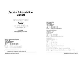
Figure 1.1 Solar in trolley
The Solar is used in combination with a computer and the MMS software program. To run the MMS program you will need the operating system Windows 2000 or Windows XP. The MMS program contains an extensive patient database which enables easy entry and retrieval of patient information. During an investigation the program controls the Solar and saves the measured data with the selected patient. When the investigation is finished you can analyse the curves and print the investigation report.
Accessories for the Solar Accessories from many different manufacturers can be used with the Solar measurement system. For detailed information MMS can supply you with the document "Declaration of conformity for MMS accessories". Ask your distributor for more information.
The MMS program is provided on CD-ROM. This software should be installed on the computer to make the complete system function (refer to chapter 3). Solar service © 2001-2005 by MMS b.v.
1-1
1-2
Solar service © 2001-2005 by MMS b.v.
Solar measurement system
Solar measurement system
1.2 MMS software program
1.3 Solar modules
The MMS software program contains four parts: ! Database program. When you start the MMS program you will enter the database in which all available patient information, investigation parameters, reports and memos are stored. Selection of a patient will give easy access to all information for that patient. ! Measurement program. This program is started from the database. The MMS software guides the user through the investigation procedure and saves the measured data with the patient. ! Analysis program. This program is started from the database. Investigation curves and parameters can be displayed, printed in investigation reports and exported to other text editor and database programs. ! Diagnostic program. This program is started from the database to test the Solar measurement system.
The Solar is a modular system which can be upgraded easily. The Solar configuration and housing determine the modules of your system. The following devices are necessary for a Solar system.
The figure below shows the MMS program.
All Solar systems Computer
Controls the Solar during the measurement and stores the investigation data for analysis afterwards. The monitor will display the measured data graphically and the printer is used to print out curves and results.
Remote control
Use the buttons to perform an investigation.
Infrared receiver
External infrared receiver that receives the signals from the remote control.
Solar trolley Safety module
Contains a power insulation between the mains and Solar system, including computer and its peripherals.
Main module or U2M module
The Solar is supplied with the main module or the U2M module, depending on your configuration. These central modules are connected by means of USB to the computer and they interface all other MMS devices (modules) to the computer. The U2M module has an integrated infrared receiver.
Solar pole and Solar chair U2M module
The central module that interfaces all MMS devices (modules) to the computer. The U2M module is connected by means of USB to the computer and has an integrated infrared receiver.
Figure 1.2 MMS program Solar service © 2001-2005 by MMS b.v.
1-3
1-4
Solar service © 2001-2005 by MMS b.v.
Solar measurement system
Depending on your Solar configuration, the Solar may have one or more of the following modules.
Solar measurement system
1.4 Solar configurations 1.4.1
Introduction
Solar modules
Description
Pump infused volume module
A water bag with saline is hanging on the hook of the infused volume module. The pump module is used to fill the bladder with saline. This weighing hook measures the infused volume.
The Solar system can be used for urodynamic, gastro-intestinal and/or neuro investigations. In this paragraph you will find some illustrations of standard Solar configurations. Depending on the configuration you have ordered your system may look different.
Combination interface module
Interface for measuring pressures (while using water perfusion catheters and/or microtip catheters), EMG, swallow, respiration and/or conductance.
1.4.2
H2O transducer interface
Pressure interface between Solar and pressure transducers (e.g. DT-XX) while using water perfusion catheters. Conductance measurement is optional.
The figure below shows a Solar system in trolley meant for urodynamic investigations. Urodynamic trolley systems are standard supplied with the Safety module and the Main or the U2M module.
Microtip catheter interface
Pressure interface between Solar and microtip pressure transducers while using microtip catheters. Conductance measurement is optional.
Digital EMG module
Measures the activity of the pelvic floor muscles.
Solar Neuro module
Via two high quality EMG inputs you are able to record EMG signals via surface, needle or wire electrodes. Stimulation of the nerve can be done via the stimulator output to measure latency time.
Flowmeter Mk III
Measures voided volume and flow. Optionally, the flowmeter can be supplied with wireless Bluetooth technology.
Flowmeter Mk II
Measures voided volume and flow. Also called Digital plugin flow sensor.
Solar Catheter puller
Withdraws the catheter with a constant speed during an urodynamic or a gastro-intestinal investigation.
Solar CO2 module
Used to fill the bladder with gas.
CIM-AUX module
This module can interface Barostat, TMPD, pH and universal signals like SaO2, blood pressure, impedance and analogue I/O.
Solar service © 2001-2005 by MMS b.v.
Solar Urodynamic system
Figure 1.3 Solar Gold trolley for urodynamic studies
1-5
1-6
Solar service © 2001-2005 by MMS b.v.
Solar measurement system
The illustration shows the following modules: ! Pump infused volume module for filling the bladder during a cystometry, pressure-flow or gynecology (combination) study. ! Combination interface module for measuring pressures, EMG (optional) and conductance (optional). ! Flowmeter for uroflow, pressure-flow or gynecology (combination) study. ! Catheter puller for UPP or gynecology (combination) study.
Solar measurement system
1.4.3
Solar GI system
The figure below shows a Solar system in trolley meant for gastrointestinal investigations. GI trolley systems are standard supplied with the Safety module and the U2M module.
Figure 1.4 shows a Solar Smart urodynamic system on a Solar pole. The pole version is standard supplied with the U2M module.
Figure 1.5 Solar trolley for GI studies
The illustration also shows the MUI perfusion system. This perfusion system can be mounted on the left or right side of the Solar trolley. In this example two Combination interface modules are mounted on the accessory rail of the perfusion pump. These modules can be used to measure pressures, swallow, respiration and EMG signals. The MUI perfusion pump is used for perfusion of the water pressure transducers and catheter.
Figure 1.4 Solar on pole for urodynamic studies Solar service © 2001-2005 by MMS b.v.
1-7
1-8
Solar service © 2001-2005 by MMS b.v.
Solar measurement system
Solar measurement system
Figure 1.6 shows a Solar GI Compact system on a Solar pole. The pole version is standard supplied with the U2M module. The illustration shows the Combination interface module for measuring pressures, swallow, respiration and EMG. The pressure cuff is for perfusion of the water transducers and catheter.
Figure 1.7 Solar GI standalone
1.4.4
Solar Neuro system
The Solar Neuro module can be integrated in a Solar urodynamic or Solar GI system as described in the previous paragraphs. It is also possible to use the Neuro module as a standalone system.
Figure 1.6 Solar GI on pole
The Solar system can also be used without Solar trolley or pole. Figure 1.7 shows the Solar GI standalone system. The system is standard supplied with U2M module. The illustration also shows the MUI perfusion system with two Combination interface modules for measuring pressures, swallow, respiration and EMG signals. Solar service © 2001-2005 by MMS b.v.
Figure 1.8 Solar Neuro system
The Solar Neuro system is standard supplied with U2M module. 1-9
1-10
Solar service © 2001-2005 by MMS b.v.
Solar measurement system
Solar measurement system
1.5 Block diagram In this paragraph you will find schematic representations of the Solar measurement system and its modules.
Figure 1.10 Solar with safety module and U2M module
Figure 1.11 Solar with U2M module
1.6 Diagnostic program The diagnostic program in the MMS software will help you test the modules after detecting a problem. Refer to the chapter describing the module or read the information in chapter 20.
1.7 Trouble shooting
Figure 1.9 Solar with safety module and main module
The Solar always works together with a computer and peripherals. You are free to choose components and computer brands. Three notes concerning hardware: ! The computer must be able to communicate via USB. ! The MMS software can run on the computer. ! The computer fits on the trolley (when available).
Although all Solar systems are tested thoroughly before they are delivered, there is always a chance that one of the parts becomes defective. The information in this manual will help you to solve hardware and software problems with your measurement system. To solve a problem, you first determine to which module it belongs. You look up the chapter describing the module and search if your problem is described. If your problem is not described or if you are not able to solve the problem with the descriptions, call your distributor.
Solar service © 2001-2005 by MMS b.v.
1-12
1-11
Solar service © 2001-2005 by MMS b.v.
Solar measurement system
Solar measurement system
1.8 Repair
1.10 Manuals and on-line help
All repairs, which are performed by the hospital personnel are for the responsibility of the hospital. MMS will not give any guarantee on a part, which has been opened, adjusted or replaced by hospital personnel. The Solar may only be opened for any adjustment, replacement, maintenance or repair by MMS qualified personnel. Send a repair information report by fax to MMS, before sending the part to be repaired (refer to appendix D in this manual).
The Solar Service & Installation manual is intended for all technical users who install the Solar software and hardware. Information is accessible because each module is described in a separate chapter. Items like safety information, installation, block diagram, diagnostics and trouble shooting can be found.
1.9 Warranty At the end of this manual you will find warranty information. Additional warranty information is described below. In case of a flow sensor malfunction, the customer has to ship the flow sensor for repair in the special MMS flow sensor box as supplied with your system. Warranty stops when the flow sensor is transported in a different box. When your MMS flow sensor box is damaged, please contact your distributor to send you a new box.
At the end of this manual you will find chapters describing: ! the diagnostic program for testing and calibration. ! the procedure for preventive maintenance and how to clean the Solar and its modules. ! the technical specifications of the different Solar modules. Details about investigations and the MMS software program can be found in the on-line help and the Reference manuals. The user’s manuals give step-by-step instructions about how to perform an investigation. Below you will find an overview of the manuals supplied with the Solar urodynamic and gastro-intestinal (GI) systems. The Solar urodynamic measurement system is supplied with: ! Solar User’s manual. ! Solar Reference manual. ! Solar Service & Installation manual. The Solar GI measurement system is supplied with: ! GI Manometry User’s manual. ! GI Manometry Reference manual. ! Solar Service & Installation manual. The Solar Neuro module is supplied with the Neuro User’s manual. The Solar Video option is supplied with the Video User’s manual. For information about options, detachable accessories, spare parts and catheters which can be used with the system, contact your distributor.
Figure 1.12 Flow sensor box
Solar service © 2001-2005 by MMS b.v.
1-13
1-14
Solar service © 2001-2005 by MMS b.v.
Installation
Installation
2 Installation
2.2 Solar trolley
2.1 Introduction
2.2.1
In this chapter you will find descriptions of the installation procedures for the Solar trolley, pole and chair systems. Is your Solar supplied without one of these items, then you can still use one of these procedures. Skip the instructions for clamping the modules on the Solar trolley, pole or chair. Note: In rare occasions, depending on your computer setup with USB devices, the Solar cannot communicate with the computer. Placing a USB hub between the Solar and the computer may solve this communication problem. WARNING Connect only MMS devices to the Solar (except the computer and the catheters). WARNING Safety can be violated if the Solar or one of its modules shows visible damage. WARNING Do not attempt to open Solar modules.
The Solar trolley is a combination of computer trolley and cabinet for the Solar electronics and modules. This trolley is easy to expand and easy to service. Most modules will fit in and on the trolley by using an accessory rail or pole. Note that your configuration may be different. Modules can also be mounted on an infusion pole or investigation chair. MMS supplies two types of trolleys, the Solar Silver and Solar Gold. The Solar Gold trolley has more accessories than the Solar Silver. For example the Solar Silver has one retractable shelf and the Solar Gold has two retractable shelves (for printer, keyboard). MMS can provide you with an upgrade kit, to upgrade the Solar Silver trolley into a Gold trolley.
WARNING MMS advises to provide all mains powered equipment with a connected equipotential wire. WARNING If a safe system setup according to the IEC-60601 can not be guaranteed, a Safety module is required. Please contact MMS. WARNING Make sure that when the patient is connected to more than one apparatus, the leakage currents will not exceed the allowed limits. Take note of IEC 60601-1-1. WARNING
Silver and Gold trolleys
Figure 2.1 Solar trolley
The Solar trolleys may be supplied with the following accessories: Solar Silver
Solar Gold
1x accessory rail 1x retractable keyboard shelf
2x accessory rail 2x retractable shelf for keyboard and printer 2x blue side shields 1x PC cable cover
The digital cables connected to the Solar modules all have a connector with locking mechanism. Do not attempt disconnection by pulling the cable. Loosen the lock by pressing the lever on the connector.
Solar service © 2001-2005 by MMS b.v.
2-1
2-2
Solar service © 2001-2005 by MMS b.v.
Installation
2.2.2
Safety information WARNING All devices must be powered via the Solar Safety module.
Please refer to the Safety information chapter at the beginning of this manual for additional information. When installing a module always read the safety information as described in the corresponding chapter.
2.2.3
Installation procedure
In this paragraph is described how to install all modules in or on the Solar trolley. When one of the modules is not a part of your configuration, you may skip the instructions. To install the modules in the Solar trolley, proceed as follows: # Make sure during the installation that the wires cannot bend or get damaged. # Install the computer, monitor, printer, keyboard and mouse by using the manual supplied by the manufacturer. # Install the MMS software as described in chapter 3. # Switch off the computer. # The blue side covers to cover most of the cables, for example from printer and pump, can be removed. # Install the Safety module as described in § 4.3. # Install the Main module as described in § 5.3. # Install the U2M module as described in § 6.3. # Place the computer on the lower shelf. Connect the Euro-euro cable from the computer to the Safety module via the backside (not via the side covers). # Place the printer on the computer or the second shelf. Connect the Euro-euro cable from the printer to the Safety module. # Install the monitor on the upper shelf. Connect the power cable from the monitor to the computer (or Safety module). The monitor cable can be led via the backside, under the upper shelf, to the side covers, and then down to the Safety module. # Install the keyboard on the keyboard shelf. Connect the cable to one of the USB ports (inputs) on the main module or computer.
Solar service © 2001-2005 by MMS b.v.
2-3
Installation
# Place the mouse on the drawer and connect it to the computer. # Connect the infrared receiver to one of the USB ports on the Main module or computer (see § 7.3). # Install the remote control as described in § 8.3. # Place the accessory rail(s) in the trolley. # Install the Combination interface module as described in § 10.3. # Install the H2O transducer interface as described in § 11.3. # Install the Microtip catheter interface as described in § 12.3. # Install the EMG module as described in § 13.3. # Install the Neuro module as described in § 14.3. # Install the Flowmeter Mk III as described in § 15.3 # Install the Flowmeter Mk II as described in § 16.3. # Install the Catheter puller module as described in § 17.3. # Install the CIM-AUX module as described in § 19.3. # Mount the blue side covers on the trolley. # Install the Pump infused volume module as described in § 9.3. # Install the CO2 module as described in § 18.3. # Install the MUI perfusion pump on the Solar accessory rail. You may mount the Combination interface module(s) on the perfusion pump. # First check that the power switch on the Safety module is off "0". Then connect the power cable from the Safety module to the mains (see § 4.3). Warning: All devices must be powered via the Solar Safety module. Refer to § 4.3 for more information. # Switch on the power on the Safety module. # When the Solar is used for video studies, you can mount the video plug in the hole under the monitor shelf.
Figure 2.2 Position video plug
In case that there is a pole on the trolley, then position the pump and the pole on one side, and the accessory railbox on the other side of the trolley.
2-4
Solar service © 2001-2005 by MMS b.v.
Installation
2.2.4
Trolley accessories
Installation
2.3 Solar infusion pole
MMS offers many accessories with the Solar trolley. Below you will find an extract of them. Ask your distributor for more information.
2.3.1
Patient chart or paper holder for accessory rail.
The Solar infusion pole is standard supplied with 4 wheels, a wheelbase, an infusion pole of 1.30 meter and a 50 cm extension pole with 4 hooks. The figure below illustrates these parts.
Components pole
Basket (160 x 160 x 160 mm) with clamp for accessory rail.
Glove holder for accessory rail.
1 2 3 4
Pump tube holder for accessory rail.
Wheelbase with 4 wheels Wheel break Infusion pole 1.30 meter Extension pole with 4 hooks
Cable holder for accessory rail. Figure 2.8 Solar pole
Solar service © 2001-2005 by MMS b.v.
2-5
2-6
Solar service © 2001-2005 by MMS b.v.
Installation
2.3.2
Installation
Safety information
2.3.3
WARNING If a safe system setup according to the IEC-60601 can not be guaranteed, a Safety module is required. Please contact MMS.
In this paragraph is described how to install all modules on the Solar infusion pole. When one of the modules is not a part of your configuration, you may skip the instructions.
WARNING Be careful while working with the Solar infusion pole. There is a risk to trip over of the cables laying on the floor.
To install the modules on the Solar pole, proceed as follows: # Make sure during the installation that the wires cannot bend or get damaged. # Install the computer, monitor, printer, keyboard and mouse by using the manual supplied by the manufacturer. Place the computer on a table or trolley. # Install the MMS software as described in chapter 3. # Switch off the computer. # Mount the U2M module on the pole and install the module as described in § 6.3. # Mount the Pump infused volume module on the pole and install the module as described in § 9.3. Mount the module not too high, below the extension pole. # Mount the CO2 module on the pole and install the module as described in § 18.3. Mount the module not too high, below the extension pole. # Mount the Combination interface module on the pole and install the module as described in § 10.3. # Install the H2O transducer interface as described in § 11.3. # Install the Microtip catheter interface as described in § 12.3. # Install the EMG module as described in § 13.3. # Install the Neuro module as described in § 14.3. # Install the Flowmeter Mk III as described in § 15.3 # Install the Flowmeter Mk II as described in § 16.3. # Mount the Catheter puller on the pole and install the module as described in § 17.3. # Connect the infrared receiver to one of the USB ports on the computer (see § 7.3). # Install the remote control as described in § 8.3. # Secure the digital cables to the pole by using a ty-rap. # Switch on the computer.
WARNING Do not hang weights > 1.0 kg simultaneously on each hook of the Solar infusion pole. WARNING When you want to move the Solar infusion pole, always check the wheel breaks. WARNING After each measurement, you have to remove water from the Solar infusion pole and its devices with a soft, dry cloth. WARNING When transporting the Solar infusion pole, always fold the catheter puller (arm) to prevent the Solar pole from tipping over. WARNING During the investigation, you may only touch the computer or connected components (like keyboard, mouse, printer) and the patient at the same time when a medical safety transformer is used for the computer and the connected components. Please refer to the Safety information chapter at the beginning of this manual for additional information. When installing a module always read the safety information as described in the corresponding chapter.
Solar service © 2001-2005 by MMS b.v.
2-7
2-8
Installation procedure
Solar service © 2001-2005 by MMS b.v.
Installation
Installation
2.4 Solar Maquet investigation chair 2.4.1
Components for Maquet chair
Besides all Solar modules, MMS will supply the following additional items for mounting the modules on a chair: ! Stainless steel assembly with mounted catheter puller on flexible arm (if applicable), U2M power supply and digital cables. ! Infusion pole extension and hook ‘cross’. ! Left and right cushioned leg extension. ! 8x M8x20 SST countersunk hexagon screw. ! 5mm hexagon screw key. ! 10x ty-rap. Additional necessary tools are: ! 8mm spanner, preferably a ring spanner or socket, for connecting the earth wire to the chair. ! Hexagon screw key set. ! 6mm hexagon screw key and a 13mm spanner, preferably a ring spanner, for adjusting the arm joints (if required). Figure 2.9 Solar pole for urodynamics
Pole for urodynamics: 1 U2M module 2 Pump infused volume module 3 Combination interface module 4 Catheter puller 5 Flowmeter 6 Perfusion for Pura channel (MMS-CUFF and MMS 5603 flow reducer set)
Solar service © 2001-2005 by MMS b.v.
2.4.2
Figure 2.10 Solar pole for GI
Pole for GI: 1 U2M module 2 Combination interface module with DT-NN transducers 3 Catheter puller 4 Perfusion (MMS-CUFF and MMS 5624 flush set)
2-9
Safety information WARNING If a safe system setup according to the IEC-60601 can not be guaranteed, a Safety module is required. Please contact MMS. WARNING The funnel ring of the flowmeter can touch the leg pads in a certain combination of seat angle and flowmeter height.
2-10
Solar service © 2001-2005 by MMS b.v.
Installation
Installation
Please refer to the Safety information chapter at the beginning of this manual for additional information. When installing a module always read the safety information as described in the corresponding chapter.
2.4.3
Installation procedure
Use the information in this paragraph to install the Solar modules on a Maquet chair. Skip the instruction of the modules which are not a part of the configuration. The procedure is as follows: # Make sure during the installation that the wires cannot bend or get damaged. # Install computer, monitor and printer by using the manual supplied by the manufacturer. Place the computer on a table or trolley. # Install the MMS software as described in chapter 3. # Switch off the computer. Mounting the assembly on the chair # Place the chair in the highest position to ease the mounting process. Place the chair’s back rest forward as far as possible. # Remove the four small plastic covers out of the chair’s column on the right side, to reveal the M8 sockets. # Mount the assembly using 4 of the M8x20 screws and tighten them real good. Refer to figure 2.12. # Remove the top cover of the chair’s column by loosening two screws to reveal the earth point of the chair. # Remove the screw, connect the earth wire of the assembly and tighten the screw again (figure 2.12). # Mount the top cover again. Figure 2.11 Connect earth wire # Mount the infusion pole extension on the assembly and turn it real tight. # Mount the hook ’cross’ on top of the infusion pole extension. Mounting leg extensions # Remove the two accessory rails from the studs on both seat sides. # Mount the left and right leg extensions on these studs, using 4 M8x20 screws. Tighten the screws real good.
Figure 2.12 Solar on Maquet chair
Solar service © 2001-2005 by MMS b.v.
2-12
2-11
Solar service © 2001-2005 by MMS b.v.