Medizin Technik
MEDAP Product Range
MEDAP Tapping Unit S Vac B 900 & D 200 Operating Instructions Ver 08 July 2020
Operating Instructions
40 Pages
Preview
Page 1
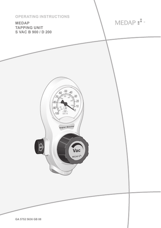
OPERATING INSTRUCTIONS MEDAP TAPPING UNIT S VAC B 900 / D 200
GA 5752 5636 GB 08
Subject to technical modification! Illustrations and technical specifications may vary slightly from those in these operating instructions as a result of ongoing product development.
V08 2020-07
4
2
GA 5752 5636 GB 08
Table of contents
Table of contents 1
Introduction... 6
1.1
Foreword... 6
1.2
How to use these operating instructions... 6 1.2.1
Abbreviations... 6
1.2.2
Symbols... 6
1.2.3
1.3
1.4
1.2.2.1
Cross-references... 6
1.2.2.2
Actions and responses... 6
Definitions... 7 1.2.3.1
Design of safety notes... 7
1.2.3.2
Design of other notes... 7
1.2.4
Symbols used... 7
1.2.5
Disposal... 8 1.2.5.1
Packaging... 8
1.2.5.2
ATMOS products... 9
Overview... 9 1.3.1
S VAC B 900 / D 200... 9
1.3.2
Versions of the S VAC B 900 / D 200... 10
Basic requirements... 10 1.4.1
Use in accordance with the intended purpose... 10
1.4.2
Applicable standards... 11
1.4.3
Intended purpose... 11
1.4.4
S VAC versions... 12
1.4.5
Interface description... 13 1.4.5.1
Vacuum connection tube... 13
1.4.5.2
Hydrophobic bacterial and viral filter... 13
1.4.5.3
Septic fluid jar including septic fluid jar cap... 14
1.4.5.4
Suction tube... 14
1.4.5.5
Fingertip... 14
1.4.5.6
Utensil... 14
1.4.5.7
Mechanical overflow protection... 15
2
Safety notes... 16
2.1
General safety notes... 16
2.2
Product safety notes... 16
3
Initial operation... 18
3.1
Product inspection... 18
3.2
Connection to the terminal unit... 18 3.2.1
General... 18
3.2.2
Version A... 18
GA 5752 5636 GB 08
3
Table of contents
3.3
3.2.3
Version B... 19
3.2.4
Version C... 19
Mounting accessories... 20 3.3.1
General... 20
3.3.2
Mounting the mechanical overflow protection... 21
3.3.3
Connection of the mechanical overflow protection... 21
3.3.4
Connection of the hydrophobic bacterial and viral filter... 22
4
Operation... 23
4.1
Function test... 23
4.2
Use in conjunction with magnetic resonance imaging scanners... 23
4.3
Setting the vacuum level... 24
5
Taking the unit out of operation... 25
5.1
Completing the aspiration process... 25
5.2
Disassembly... 25 5.2.1
General... 25
5.2.2
Dismantling the mechanical overflow protection... 26
6
Cleaning and disinfection... 27
6.1
General... 27
6.2
Cleaning... 28
6.3
6.2.1
General... 28
6.2.2
Cleaning procedure... 28
Disinfection... 28 6.3.1
General... 28
6.3.2
Suitable disinfectants... 29
6.3.3
Disinfection procedure... 29
6.3.4
Disinfection procedures... 29
6.4
Product-specific safety notes... 30
7
Maintenance... 31
7.1
General... 31
7.2
Periodic tests... 31
7.3
Malfunctions and troubleshooting... 31
7.4
Repairs... 32
7.5
Service hotline... 32
7.6
Type plate position... 32
7.7
Sending in the device... 32
8
Technical specifications... 34
8.1
General... 34
8.2
Technical specifications... 34
8.3
Ambient conditions... 34
8.4
Dimensions and weight... 34
4
GA 5752 5636 GB 08
Table of contents
9
Approved accessories... 35
9.1
Accessories... 35
9.2
Accessories for compact suction unit / basic vacuum equipment... 35
9.3
Accessories for mobile suction unit / basic vacuum equipment... 35
9.4
Consumables... 36
GA 5752 5636 GB 08
5
1
Introduction Foreword
1
Introduction
1.1
Foreword Your facility has selected the leading-edge medical technology made by ATMOS. We sincerely appreciate the trust you have placed in us.
1.2
How to use these operating instructions These operating instructions are provided to familiarise you with the features of this ATMOS product. They are subdivided into several chapters. Please note: • Please read these operating instructions carefully and completely before using the product for the first time. • Always proceed in accordance with the information contained herein. • Store these operating instructions in a location near the product.
1.2.1
Abbreviations EN EEC VDE
1.2.2
Symbols
1.2.2.1
Cross-references
European standard European Economic Community Verband der Elektrotechnik Elektronik Informationstechnik (Association for Electrical, Electronic & Information Technology)
References to other pages in these operating instructions are identified with a double arrow symbol ‘’. 1.2.2.2
Actions and responses The ‘’ symbol identifies an action taken by the user, while the ‘’ symbol identifies the reaction that this will induce in the system. Example: _ Turn on the light switch. 9 Lamp lights up.
6
GA 5752 5636 GB 08
Introduction How to use these operating instructions
1.2.3
Definitions
1.2.3.1
Design of safety notes Pictogram
Descriptor
Text
DANGER!
The text for the safety note describes the type of risk and how to avert it.
Indicates a direct and immediate risk to persons which may be fatal or result in most serious injury.
1
WARNING! Indicates a potential risk to persons or property which may result in health hazard or grave property damage. CAUTION! Indicates a potential risk to property which may result in property damage. Tab. 1:
1.2.3.2
Design of safety notes
Design of other notes Notes not referring to personal injury or property damage are used as follows: Pictogram
Tab. 2:
1.2.4
Descriptor
Reference to
NOTE
Supplementary assistance or further useful information.
ENVIRONMENT
Information regarding proper disposal.
Design of other notes
Symbols used Symbols are attached to products, type plates and packaging. Symbols
Identification
4
Labelling for products which were developed and are marketed in compliance with the Medical Devices Directive 93/42/EEC. Class Is, Im, IIa, IIb and III products are also marked with the identifying number of the Notified Body. Labelling in compliance with the ISO 15223-1 standard. Symbol for ‘Serial number’. Labelling in compliance with the ISO 15223-1 standard. Symbol for ‘Product number’.
GA 5752 5636 GB 08
7
1
Introduction How to use these operating instructions
Symbols
Identification Labelling in compliance with the IEC 60601-1 standard. Symbol for ‘Follow operating instructions’. Labelling in compliance with the ISO 15223-1 standard. Symbol for ‘Name and address of the manufacturer as well as date of manufacture’. Labelling in compliance with the IEC 62570 standard. Symbol for ‘Conditionally MR safe’. Packaging label. Symbol for ‘Keep dry’. Packaging label. Symbol for ‘Fragile! Handle with care’. Packaging label. Symbol for ‘Top’. Labelling in compliance with the ISO 15223-1 standard. Symbol for ‘Temperature limitations’. Labelling in compliance with the ISO 15223-1 standard. Symbol for ‘Relative humidity’. Labelling in compliance with the ISO 15223-1 standard. Symbol for ‘Atmospheric pressure’.
Tab. 3:
1.2.5
Symbols
Disposal WARNING! Infection hazard! The product or some of its components may be contaminated after use. Clean and disinfect the product before disposal.
1.2.5.1
Packaging The packaging is made of materials compatible with the environment. ATMOS will dispose of the packaging materials upon request.
8
GA 5752 5636 GB 08
Introduction Overview
1.2.5.2
1
ATMOS products ATMOS will take back used products or those which are no longer in service. Please contact your ATMOS representative for more detailed information.
1.3
Overview
1.3.1
S VAC B 900 / D 200 5
1
4
7
2
6
3
8
9
Fig. 1:
Overview of S VAC B 900 / D 200
1 S VAC B 900 2 Vacuum gauge 3 Control valve 4 OFF button
5 S VAC D 200 6 ON button 7 Mechanical overflow protection 8 Adapter for hydrophobic filter 9 Hydrophobic bacterial and viral filter
GA 5752 5636 GB 08
9
1 1.3.2
Introduction Basic requirements
Versions of the S VAC B 900 / D 200 1
4 8
3
2
5 6 9
7
Fig. 2:
Overview of versions S VAC B 900 / D 200
1 Version A Tapping unit with integrated gas pin 2 Plug 3 Terminal unit 4 Version B Tapping unit with rail clamp and NIST connection
6 NIST screw connection 7 Connection tube 8 Rail clamp 9 Version C Tapping unit for screw connection, with NIST connection
5 NIST nipple
1.4
Basic requirements
1.4.1
Use in accordance with the intended purpose Product As per Annex IX to the Medical Devices Directive 93/42/EEC, this product belongs to class IIa. In accordance with this directive, the product may only be used by persons who have been instructed how to use this product by an authorised person. This product is to be used exclusively for human medicine. When employed in commercial or business use, this product must be entered in the inventory.
10
GA 5752 5636 GB 08
Introduction Basic requirements
1
Accessories Accessories or combinations of accessories may be utilised only as and when indicated in these operating instructions. Other accessories, combinations of accessories and consumable items may be used only if they have a valid certification, are intended expressly for the particular use and will not adversely affect performance, the prescribed ambient conditions or safety requirements. 1.4.2
Applicable standards The product satisfies the basic requirements set forth in Annex I to Council Directive 93/42/EEC concerning medical devices (Medical Devices Directive) as well as the applicable national (German) codes and the Medical Devices Act (MPG) in Germany. This is certified by compliance with harmonised standards such as IEC 60601-1 and related standards and the respective special sections.
1.4.3
Intended purpose Name:
S VAC B 900 S VAC D 200
Main function:
Aspiration of secretion, blood, serous fluids, vomit and rinsing fluids along with any contained particles (S VAC B 900). Aspiration of secretion, blood and serous fluids (S VAC D 200).
Medical indications / application:
For all applications which require aspiration, e.g. general surgeries (e.g. aspiration of wound cavities, abscesses), bronchial aspiration, during endoscopy for aspiration of secretions and in neurosurgery (S VAC B 900). For precise regulation of vacuum for postoperative aspiration of wound exudate, secretion, blood or serous fluids. Additional fields of application are the aspiration of air as well as rinsing and wound drainage (S VAC D 200).
Specification of the main function:
Drainage and temporary collection of body fluids. For the supply of vacuum, S VAC B 900 and S VAC D 200 are connected to a terminal unit for vacuum of a central medical gas supply system with a pressure of −100 kPa to −60 kPa. A septic fluid jar, which has to be used, allows for temporary collection of drained body fluids.
User profile:
Doctor, medically trained staff
Patient groups:
Patients of all ages
Application organ:
Natural and artificial body orifices
Application time:
For continuous operation; in practice, short-term use on the patient (< 30 days)
Application site:
The application site is the clinical environment and doctor’s practices which have a central vacuum source. The application of the product may only be performed by medically trained and instructed staff.
GA 5752 5636 GB 08
11
1
1.4.4
Introduction Basic requirements
Contraindications:
The S VAC B 900 and D 200 may not be used for the following purposes: • Outside the medical sector • In MR areas > 4.7 Tesla • In the home care sector • Being operated directly by the patient • For vacuum extraction • For the aspiration of flammable or explosive liquids • For the aspiration of smoke that is generated during HF and laser surgery without the connection of an intermediate smoke filter • S VAC D 200 is not suitable for bronchial aspiration. • S VAC B 900 is not suitable for drainages. • S VAC B 900 and D 200 are not suitable for thoracic drainages. Usage in combination with disposable thoracic drainage systems with integrated vacuum regulation is excepted from this restriction. • With central gas supply systems with supply pressures other than −100 kPa to −60 kPa
The product is:
Active
Sterility:
Not a sterile product
Single-use product / reprocessing:
The device and parts of the accessories are reusable. For information on reprocessing, cleaning and disinfection, please see the operating instructions.
S VAC versions The connection of S VAC (regardless of which version S VAC B 900 or S VAC D 200) to the vacuum terminal unit will depend on the product type. Version A: Tapping unit with integrated gas pin • S VAC is fitted directly to the terminal unit. Version B: Tapping unit with rail clamp and NIST connection • S VAC is designed for mounting to a 25–35 x 10 mm equipment rail in accordance with DIN EN 19054 and is supplied via a NIST connection with vacuum from a terminal unit connected using a connection tube with gas probe. Version C: Tapping unit for screw connection, with NIST connection • S VAC is designed for direct screw mounting onto mobile suction units (intensive care trolley / surgical trolley) and compact suction units (solo carrier frame) and is supplied from a terminal unit via a NIST connection with a connection tube and gas probe. Products and accessories are only permitted with ISO colour coding. In Germany, Austria and Switzerland, products with neutral colour coding are also permitted. NOTE The products are supplied with ISO coding. The scope of delivery for the versions DIN, MEDAP, equipment rail and screw mount also includes a label for neutral colour coding.
12
GA 5752 5636 GB 08
Introduction Basic requirements
1
The S VAC B 900 is available in the following versions: • S VAC B 900 Wall DIN (REF 5752 5619) • S VAC B 900 Wall MEDAP (REF 5752 5620) • S VAC B 900 Wall BOC (BS 5682) (REF 5752 5621) • S VAC B 900 Wall Air Liquide (NF S 90-116) (REF 5752 5622) • S VAC B 900 Wall AGA (SS 87 524 30) (REF 5752 5623) • S VAC B 900 Equipment rail (REF 5752 5624) • S VAC B 900 Screw connection (REF 5752 5625) The S VAC D 200 is available in the following versions: • S VAC D 200 Wall DIN (REF 5752 5626) • S VAC D 200 Wall MEDAP (REF 5752 5627) • S VAC D 200 Wall BOC (BS 5682) (REF 5752 5628) • S VAC D 200 Wall Air Liquide (NF S 90-116) (REF 5752 5629) • S VAC D 200 Wall AGA (SS 87 524 30) (REF 5752 5630) • S VAC D 200 Equipment rail (REF 5752 5631) • S VAC D 200 Screw connection (REF 5752 5636) 1.4.5
Interface description All devices and accessories which are combined with the tapping unit must be listed in the accessories list or meet the specifications of the interface description. Configuration of the overall system as well as functional testing are subject to the overall responsibility of the medical staff. Functionality and suitability of the connected accessory for each intended application must be checked by the operator before every use. This includes the functionality of the connector components, airtightness and suitability regarding material properties, working pressure and flow rate.
1.4.5.1
Vacuum connection tube The vacuum connection tube is used to connect the tapping unit and the septic fluid jar. Technical specifications • Shore hardness of 60 • Inner diameter 6 mm • Length 50 cm (± 10 cm) • Vacuum resistant down to −95 kPa (must not collapse) Prerequisites • The inner diameter of the vacuum connection tube should match the outer diameter of the tube connector on the septic fluid jar cap of the pump. The vacuum connection tube will be referred to only as ‘connection tube’ below.
1.4.5.2
Hydrophobic bacterial and viral filter In its function as overflow protection, the hydrophobic bacterial and viral filter protects the product against ingress of particles, fluid and foam. In its function as bacterial and viral filter, it protects the product against the ingress of bacteria and viruses.
GA 5752 5636 GB 08
13
1
Introduction Basic requirements
Prerequisites • Pore size ≤ 1.0 μ. • The tube connector must match the tube being used. • The hydrophobic bacterial and viral filter must close tightly against water passage at an absolute pressure of up to 10 kPa. • If required, observe the direction of flow (see note on the hydrophobic bacterial and viral filter). 1.4.5.3
Septic fluid jar including septic fluid jar cap The septic fluid jar and septic fluid jar cap are used to collect the secretions extracted. Prerequisites • Low leakage. • Always fasten the septic fluid jar securely. • The outer diameter of the tube connector on the patient side should match the inner diameter of the suction tube.
1.4.5.4
Suction tube The suction tube is used to connect the tube connector on the septic fluid jar on the patient side and the fingertip or the utensil. Technical specifications • Shore hardness of 60 • Inner diameter 6–8 mm • Length 1.3–3.0 m • Vacuum resistant down to −95 kPa (must not collapse) Prerequisites • The outer diameter of the tube connector on the patient side of the septic fluid jar cap must match the inner diameter of the suction tube.
1.4.5.5
Fingertip The fingertip serves to vent the suction tube in order to be able to quickly interrupt the aspiration process. Prerequisites • It must be possible to sterilise the fingertip or it must be a sterilised disposable item. • The outer diameter of the tube connector on the patient side should match the inner diameter of the suction tube.
1.4.5.6
Utensil The suction catheter, lance, etc., are referred to as utensils. The utensils are used to extract septic fluids. Prerequisites • The inner diameter of the utensil's connector must match the outer diameter of the fingertip. • The utensil must be sterilisable or a sterile single-use item. • Biocompatibility. • For endobronchial extraction, a utensil with side openings must be used.
14
GA 5752 5636 GB 08
Introduction Basic requirements
1.4.5.7
1
Mechanical overflow protection The mechanical overflow protection device protects the product against the ingress of particles and fluid. The tube connector must match the vacuum connection tube.
GA 5752 5636 GB 08
15
2
Safety notes General safety notes
2
Safety notes
2.1
General safety notes DANGER! Danger to life! Danger due to unauthorised modifications. The product may not be modified. WARNING! Risk of injury! Hazard resulting from incorrect handling. Be absolutely sure to observe the operating instructions for all the products used in the configuration. CAUTION! ATMOS recommends always having another aspirator ready to hand. That way you can perform aspiration even in the event of product failure.
2.2
Product safety notes WARNING! Risk of injury to mucous membranes! Endobronchial aspiration in paediatrics and neonatology requires particularly careful limitation of the vacuum. For regular endobronchial aspiration in paediatrics and neonatology, the tapping unit S VAC D 200 from ATMOS should be used. WARNING! Risk of injury! ATMOS products may be used only when fully functional. Ensure that the ATMOS product is fully functional and in good working order prior to use. DANGER! Infection hazard due to oversuction! To avoid the ingress of fluid or foam into the product or the vacuum source, a hydrophobic filter must be used. If secretion enters the inside of the unit, the product must immediately be taken out of operation. Clean and disinfect the product and have it repaired by a service technician authorised by ATMOS to do so. DANGER! Infection hazard due to contamination! To avoid the ingress of contaminants into the product or the vacuum source, a bacterial and viral filter must be used. If bacteria or viruses enter the inside of the unit, the product must immediately be taken out of operation. Clean and disinfect the product and have it repaired by a service technician authorised by ATMOS to do so.
16
GA 5752 5636 GB 08
Safety notes Product safety notes
2
WARNING! Impacts! Impacts may cause damage to sensitive, precision mechanical components. Do not expose the product to impacts. WARNING! Measuring accuracy / oversuction! The product may only be operated in a vertical position. WARNING! Foaming! Foam may be created when extracting secretion. Foam is detrimental to the functioning of the mechanical overflow protection. This raises the risk that secretions may penetrate the product and cause it to break down. Use an ordinary foam inhibitor. WARNING! Non-permissible load! If the permissible load is exceeded, leakages may occur at the connection between the terminal unit and the gas probe. In accordance with DIN EN ISO 9170-1, the overall weight of the product and accessories may not exceed 2 kg. WARNING! Backflow of aspirated secretion! In the event of oversuction, the aspirated secretion may flow back to the patient if there is secretion still left in the suction tube. Before replacing the septic fluid jar in the event of oversuction or switching off the vacuum, always remove the tube from the patient first. WARNING! Risk of injury! Immediately replace the hydrophobic bacterial and viral filter if it is discoloured, contaminated or oversucked. Furthermore, the filter must be changed if the vacuum displayed is above −0.3 bar / −30 kPa when the vacuum controller is in the ‘max’ position and the suction tube is open (S VAC D 200: −0.2 bar / −20 kPa). WARNING! Risk of injury! The product may not be used for the following purposes or under the following conditions: • Never throw, hit or drop the product. • The product is not suitable for vacuum extraction. • The product may not be used without a hydrophobic filter. • The product may not be used without a bacterial and viral filter. • The product may not be used without a septic fluid jar. • The product may not be used without a fingertip. • The product is not autoclavable.
GA 5752 5636 GB 08
17
3
Initial operation Product inspection
3
Initial operation
3.1
Product inspection DANGER! Product inspection! Only product parts which are in perfect condition can ensure proper functioning of the product. The product parts will thus have to be carefully inspected before mounting. WARNING! Infection hazard! Contaminated components may endanger the health of staff and patients. Ensure the product is prepared as per hygiene standards before using it for the first time. NOTE In order to ensure the functionality, carry out a function check prior to use.
3.2
Connection to the terminal unit
3.2.1
General NOTE Please refer to the manufacturer’s instructions for the particular terminal unit for information on connecting the gas probe to the terminal unit.
3.2.2
Version A Tapping unit with integrated gas pin 2
1
Fig. 3:
18
Version A
GA 5752 5636 GB 08
_ The tapping unit (1) is plugged directly into the terminal unit (2).
Initial operation Connection to the terminal unit
3.2.3
3
Version B Tapping units with rail clamp and NIST connection 1 2 8
7
_ With the upper edge of the guide groove at the front, position the rail clamp (1) at a slight angle on the equipment rail (2) and then press it against the equipment rail and allow it to click into place. _ Tighten the handle screw (3) of the rail clamp. _ Make sure that the rail clamp is correctly secured and that the tapping unit is in a stable position on the equipment rail.
3
Fig. 4:
3.2.4
_ Insert the NIST nipple (4) of the connection tube into the NIST connection (5) of the tapping unit and tighten down the NIST screw connection (6) by hand.
6
4
5
_ Plug the gas probe (7) of the connection tube into the terminal unit (8).
Version B
Version C The tapping unit for screw connection may be connected to an intensive care trolley, surgical trolley or solo aspiration set carrier frame. The solo aspiration set carrier frame is used to show the assembly. Tapping unit for screw connection, with NIST connection _ Press the tapping unit (1) up against the carrier frame. 1
_ Put the lock washers (3) onto the hexagon screws (4).
3
4
Fig. 5:
9 The drilled holes of the tapping unit are positioned over the drilled holes (2) of the carrier frame.
_ Use the hexagon screws to screw the tapping unit into place. 2
Version C
GA 5752 5636 GB 08
19
3
Initial operation Mounting accessories
_ Insert the NIST nipple (1) of the connection tube into the NIST connection (2) of the tapping unit and tighten down the NIST screw connection (3) by hand.
2 1 4
_ Plug the gas probe (4) of the connection tube into the terminal unit (5).
3
5
Fig. 6:
Connection tube
3.3
Mounting accessories
3.3.1
General WARNING! Tensile forces! The connected accessories must not exert any mechanical forces which could adversely affect the secure fit of the product. WARNING! Tensile forces! Hold the basic unit with one hand when installing or removing accessories in order to compensate for the tensile forces which are created. NOTE Refer to the manufacturer's instructions for additional information on the use of the septic fluid jar and the extraction utensil. NOTE The particle filter must be changed whenever the product is prepared for use.
20
GA 5752 5636 GB 08