medtronic
Medtronic Nerve Integrity Monitors ( NIM )
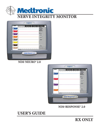
NIM - NEURO 2.0 and RESPONSE 2.0 Nerve Integrity Monitor Users Guide Sept 2007
Users Guide
40 Pages
Preview
Page 1
0123
MEDTRONIC XOMED INC. 6743 Southpoint Drive North Jacksonville, FL 32216 USA
Medtronic B.V. Earl Bakkenstraat 10 6422 PJ Heerlen The Netherlands Tel.: 011-31-45-566-8000 Fax: 011-31-45-566-8668
EC REP
™ are trademarks and ® are registered marks of Medtronic Xomed, Inc. HP DeskJet™ is a trademark of Hewlett Packard Company All of MedtronicENT’s currently released documents are available for viewing/printing @ www.medtronicENT-TechComms.com © 2007 Medtronic
The information contained in this document was accurate at time of publication. Medtronic reserves the right to make changes in the product described in this manual without notice and without incorporating those changes in any products already sold.
Definitions NIM™ - Nerve Integrity Monitor NIM- 2.0 - NIM-Neuro® 2.0, NIM-Response® 2.0 EMC - Electromagnetic Compatibility ECU protection - Electrocautery Unit Protection
SYMBOLS Power Off/Power On Type BF Applied Part Fuse Patient Cable 0123
TABLE OF CONTENTS
Page Definitions...3 Symbols...3 Warnings and Precautions ...4 Device Description...6 Indications for Use...6 Contraindications...6 Unpacking the NIM-2.0...6 Introduction...6 The Front Panel...6 The Rear Panel...6 The Main Display...7 The Patient Interface...7 The Patient Interface Fuse...8 Probes and Handles...8 The Muting Probe...8 The NIM-2.0 System Patient Simulator...9/Appendix C Electrodes and Ground...9 Self test and Touch Screen Calibration...9 Audio – Understanding What You Hear...10 Alarms...10 Stimulus...10 Adjustments and Option section...10 General User Interface Overview...10 Settings: EMG Tab...11 Settings: Audio Tab – Selecting audio options...12 Settings: Display Tab – Display Adjustments...12 Settings: System – Adjusting System Information...12 The Main Display (EMG Screen)...13 Special Functions and Features...14 Reading the EMG Screen...14 Measurement Cursor...14 Auto Event Threshold...14 Event Capture or Largest...14 Quick Help ...15 Freeze...15 Output Device Button (Print or Save)...15 Patient Information...15 Muting...15 Muting Conditions...16 Stim Bur Guard...16 System Setup...17 Operating Room Set-Up...17 Muting Probe Set-Up...17 Recommended Patient Interface Set-Up...17 Stimulator, Patient Interface, Electrodes and Patient...18 Monitor Set up (Standard)...19 Custom Set-Up (deleting custom set-ups)...20 Renaming Channel Label...21 Renaming Set-Up...21 Cleaning and Maintenance...21 Cleaning (after each use)...21 Storage...22 Maintenance...22 Fuses . ...22 Troubleshooting...22 Technical Specifications...24 Guidance and manufacturer’s declaration – electromagnetic immunity and emissions...25 Limited Warranty...27 Appendix A System Components & Accessories...28 Appendix B Preventive and Corrective Maintenance...29 Appendix C Patient Simulator...30 Appendix D Data Files...35 Appendix E Touchscreen Protector...39
This device complies with medical device directive 93/42/eec Printer Out Input / output
EC REP
IP21
Authorized representative in the European community Indication of the degree of protection of the enclosure: 1st number: 2 – protects against fingers touching hazardous parts 2nd number: 1 – equipment is minimally protected from dripping Anode Jack Cathode Jack
AUX
Cathode Auxiliary Jack RF Transmitter (Interference May Occur) Equipotential Electrode Return (ground) Jack for NIM 2.0 System Headphone out Bipolar Anode/Cathode Stimulator Probe diagram for NIM 2.0 System Monopolar Stimulus Return (Anode) Audio Out Monopolar Stimulus Probe (Cathode) Do not dispose of this product in the unsorted municipal waste stream. Dispose of this product according to local regulations. See http://recycling. Medtronic.Com for instructions on proper disposal of this product. Voice Monitoring Screen Control - On Icon is color coded to match channel Tone Monitoring Screen Control - On Icon is color coded to match channel Key Patient Interface
3
Warnings and Precautions It is important that the NIM 2.0 System operator be familiar with this manual, its precautions, procedures and safety issues. Four labels are used in this manual to identify important concerns, conditions, or procedures: • Warnings: Describes serious adverse reactions and potential safety hazards that can occur during the proper or improper use of a device. • Precautions: Any special care to be exercised by a practitioner or patient for the safe and effective use of the device. • Additional Precautions: Identifies conditions or practices that could result in damage to the equipment. • Note: Identifies special information or to clarify/emphasize important instructions. Warnings:
4
W1
The NIM 2.0 System does not prevent the surgical severing of nerves. If monitoring is compromised, the surgical practitioner must rely on alternate methods, or surgical skills, experience, and anatomical knowledge to prevent damage to nerves.
W2
To avoid patient burns: W2a
Do not activate electrosurgical Instrument while the stimulator is in contact with tissue.
W2b
Do not leave stimulating electrodes or probes in surgical field.
W2c
Do not store stimulating electrodes or probes in electrosurgical Instrument holder.
W2d
Do not allow a second surgeon (i.e. fat harvesting) to use electrosurgical instrument while stimulator is in use.
W2e
Special operator attention may be required for stimulus currents exceeding 2 mA RMS/cm2. The RMS value of current is generally lower than the stimulator current setting in mA. To calculate RMS current, waveform morphology, pulse width, repetition rate, and the stimulator current delivered must be considered.
W3
While Muting is activated, auditory and visual monitoring are disabled.
W4
To avoid false negative responses, verify stimulator current setting is high enough, and verify stimulus delivery by tone, voice, or display. Low stimulator current may cause a false negative response.
W5
High stimulator current may cause involuntary patient movement resulting in patient injury.
W6
High stimulator current activating of the fifth cranial nerve or Mastication muscles may cause tongue lacerations.
W7
False negative responses (failure to locate nerve) may result from: W7a
Shorted EMG electrode or cabling (conductive parts of applied needle electrodes or cables contacting each other).
W7b
Patient Interface fuse blown (32 mA, 250V. Xomed Part No.: 8250615).
W7c
Patient Interface defective.
W7d
Inadequate stimulus current.
W7e
Inadequate current for stimulation of nerve through hardware, such as stimulus dissection instruments, may vary based on the physical size, shape characteristics, and design of the hardware and proximity to the nerve.
W7f
Neuromuscular fatigue from prolonged or repeated exposure to electrical stimuli.
W7g
Inadvertent simultaneous current delivery from both Stimulator (Patient Interface) probe outputs. This may result in current shunting, division between the stimulator probes.
W7h
Shorted internal amplifier (characterized by baseline activity of < 3 µV p-p).
W8
Do not power-on the NIM 2.0 System when the stimulator is in the surgical field.
W9
To avoid eye injury during electrode placement, the electrode needles should be directed away from the globe and adequately secured with tape.
W10
To avoid the risk of fire or explosion, do not use the NIM 2.0 System in the presence of flammable anesthetics and/or oxygen rich environments.
W11
To avoid electrical shock, do not attach unapproved components or accessories to the NIM 2.0 System.
W12
To avoid the risk of infection while using the NIM 2.0 System touchscreen stylus, the user must maintain good sterility practices.
W13
Electrocardiogram monitoring artifacts may be caused by NIM 2.0 System stimulus current delivery or EMG electrode impedance monitoring.
W14
Direct stimulator contact may disrupt the operation of active implanted devices.
W15
While stimulating, it is recommended to use only approved EMG monitor(s) equipped with active audio and/or visual current delivered feedback systems to ensure delivery of current to intended tissues.
W16
Proper handling, insertion, and placement of electrodes and probes is critical for safe and accurate EMG monitoring: W16a
Improperly placed or bent needles increase the risk of needle breaking off in the patient.
W16b
Do not attempt to straighten bent needles because this may cause stress and weaken device, causing needle to break off in patient.
W16c
Extreme care must be taken when handling instruments with sharp points or edges.
W17
The surgical practitioner must choose the appropriate size electrodes and probes based on the procedure to be performed and the stimulating current necessary for the application.
W18
Avoid trans-thoracic stimulation; when possible, maintain anode and cathode stimulating sites in close proximity.
W19
Reuse of single use electrodes and probes increase the risk of infection and may cause degraded or ineffective monitoring.
Precautions P1
Use of the NIM Stimulator Probe is recommended for positive nerve identification. P1a
Special care must be exercised to distinguish between the high-pitched beep of the Event Tones (EMG activity over threshold), and the Stimulus Warble Tone (indicates the set current is being delivered)
P2
When the “Bleedle Alarm” (BLEE-dle-DEET) sounds, the cause must be identified and eliminated immediately.
P3
To avoid loud, extraneous monitoring noise during electrosurgical unit activation, ensure the Muting Probe is properly attached to the active electrosurgical lead.
P4
Inadequate stimulus current flow may be caused by non-flush contact between the stimulating electrode or probe and the nerve, inadequate stimulator probe electrical contact surface area, or high impedance.
P5
Inability to deliver stimulus current flow may be caused by:
P6
P5a
Stimulator return electrode not connected, or other incomplete electrical connection between the NIM 2.0 System, monitoring electrode and stimulator probe.
P5b
STIM 1 (EMG) Patient Interface fuse blown (32 mA, 250 V, REF 8250615).
P5c
Stimulus set to 0.00 mA.
P5d
Defective stimulating electrode or probe.
To avoid false positive EMG events (stimulus artifacts): P6a
Ensure the recording electrodes and the stimulator (+) or (-) cabling are routed separately and not tangled.
P6b
Ensure EMG ground (green wire) is physically placed between the stimulator return electrode (white wire with red plug) and the EMG channel input electrodes.
P7
Proper placement and setup of the electrosurgical unit away from the NIM 2.0 System will reduce or minimize unnecessary muting, interference, and offsets.
P8
Use of unapproved stimulators, stimulus probes, stimulus-dissection instruments or electrodes may result in compromised NIM 2.0 System operation, such as, but not limited to, decreased accuracy.
P9
Electrode integrity should be checked (on the “electrodes” screen) after electrode insertion and before electrode removal to give additional assurance that electrode continuity was maintained throughout the entire procedure. If electrode impedance is very high, discontinue use and replace.
P10
The Patient Interface cable, and Muting Probe cable should be secured to the floor with tape or other non-trip device.
P11
Excessive or insufficient muting may result from improper muting gain. For excessive muting, move the Muting Probe to a Lower jack number. For insufficient muting, move the Muting Probe to Higher jack number. Standard position is number 3.
P12
To avoid excessive muting: P12a
Do not place the NIM 2.0 System in close proximity to the electrosurgical unit.
P12b
Do not place Patient Interface or electrode wires in close proximity to the electrosurgical unit or electrosurgical unit wires.
P12c
Avoid high-power electrosurgical unit monopolar settings. Note: that muting caused by electrode charging may last several seconds after electrosurgical Instrument use.
P12d
Be aware of external sources that may induce muting including cellular phones, diathermy, electrocautery used in adjacent operating rooms, or other sources of electromagnetic interference.
P13
Avoid accidental contact between connected but unapplied electrodes and other conductive parts.
P14
Contaminated single use electrodes and probes must be disposed of in an appropriate sharps biohazard container in accordance with hospital or other user facilities policy.
P15
For extra-ocular monitoring, it is recommended that electrode placement be done under the direction of a neurologist or ophthalmologist.
P16
The Patient Interface safety fuse used in all NIM Patient Interfaces Boxes for the Stimulator Output are specifically tested for ECU protection. Use Xomed 11270048 Fuse, 5 x20mm, 32mA, 250 V. Order 8250615 Fuse Kit for replacements.
Additional Precautions AP1
To avoid system damage, do not connect any device other than NIM 2.0 System Muting Probes into any of the four muting probe inputs on the rear panel of the NIM 2.0 System.
AP2
Disconnect the power of the NIM 2.0 System or a connected printer before cleaning. To prevent cleaning solutions from seeping into the electronic portions of the instrument, spray cleaner lightly on a cotton cloth, then wipe the instrument with the cloth. Be especially careful around the controls, connectors and panel edges. Do not use abrasive cleaners (especially on the touch screen).
AP3
Repair and/or modification to the NIM 2.0 System, or any accessory by anyone other than qualified service personnel may significantly compromise the units ability to monitor nerve activity and/or void the equipment warranty. For best performance, it is recommended that all service be performed by Medtronic Xomed service personnel. The Manufacturing Test is not intended for end users and is to be used only under the direct supervision of Medtronic Xomed Personnel.
AP4
Medical Electrical Equipment needs special precautions regarding EMC and needs to be installed and put into service according to the EMC information provided in this Guide. 5
AP5
Portable and mobile RF communications equipment can affect Medical Electrical Equipment.
AP6
Use of accessories and cables other than those specified and sold by Medtronic Xomed may result in increased emissions and decreased immunity of this unit.
AP7
The NIM 2.0 System should not be used adjacent to or stacked with other equipment. If adjacent or stacked use is necessary, the NIM 2.0 System should be observed to verify normal operation in the configuration in which it will be used.
important notice This User’s Guide covers the NIM-Neuro® 2.0, and NIM-Response® 2.0. The only difference is the number of channels available for monitoring (the NIM-Neuro® 2.0 has eight channels, the NIM-Response® 2.0 has four channels).
introduction (Basic components and Functions) The Front Panel
DEVICE DESCRIPTION Device Description The NIM-Neuro® 2.0 is an eight-channel EMG monitor for intraoperative use during surgeries in which a motor nerve is at risk due to unintentional manipulation. The NIM 2.0 System records electromyographic (EMG) activity from muscles innervated by the affected nerve. The monitor will assist early nerve identification by providing the surgeon with a tool to help locate and identify the particular nerve at risk within the surgical field. It will continuously monitor EMG activity from the muscles innervated by the nerve at risk to minimize trauma by alerting the surgeon when a particular nerve has been activated. Indications for Use This device is intended for use in surgical procedures for patientconnected intraoperative nerve monitoring, i.e. assisting the surgeon in locating and mapping motor nerves through the use of electromyographic (EMG) signals and electrical stimulus of nerves. This device is indicated for locating and identifying cranial and peripheral motor nerves during surgery.
A: The Touch Screen displays EMG waveforms and controls many of the functions of the NIM. B: The Speaker provides audio alarms, acoustic EMG monitoring, and voice prompts. C: The Software Version installed is displayed on the start-up “splash screen”. D. Build Date and Build number.
Contraindications
The Rear Panel
The use of paralyzing anesthetic agents will significantly reduce, if not completely eliminate, EMG responses to direct or passive nerve stimulation. Whenever nerve paralysis is suspected, consult an anesthesiologist.
All connections to the NIM 2.0 System console are via the rear panel. Please connect accessories in strict accordance with the information below.
Unpacking the NIM 2.0 System When you unpack the NIM 2.0 System, save the cartons and packing material in which your monitor arrived. If the instrument is to be shipped from one location to another, the custom designed shipping package will provide the best protection. When the box is unpacked, check off the contents of the box against the items listed on the packing slip. If the contents are incomplete, or if there is damage, notify MEDTRONIC XOMED Customer Service. If the shipping container is damaged, or the cushioning material shows signs of stress, notify the carrier as well. Keep the shipping materials for carrier inspection.
E
B
N
D
C
M
F
A
I
H
G
L
J
NIM-Neuro® 2.0 REF 8250650 S N NN- xxxxxx
K
A. Equipotential: uniform potential. B. USB Out: The USB Out is an industry standard USB type connector (two port) that can be used with mass storage devices. Note: See Appendix D for more information. C. VGA Output: A VGA output is available through the standard VGA 15 pin connector on the back panel. The NIM 2.0 System can be connected directly to a VGA monitor. D. Mini Jack: Standard configuration is for private listening through Stereo Headphones. E. Printer Port: The printer port is a Centronics printer port that can be used with standard industry supported printers. 6
F. Muting Probe Inputs: There are four Muting Probe Inputs. G. Power Connector: The power cord plugs into the back of the NIM 2.0 System console. The input fuses and accessory output is in the power entry module. Plug the power cord into the A/C power outlet. H. Power Switch: The power switch turns the power ON or OFF. I. Fuse Access: The AC power fuses are located on the back of the units. See fuse kit insert for instructions on changing the fuse. J. Patient Interface Connector: The patient interface connector is a 25-pin D-sub. K. Factory / Custom Mode Switch: The Factory/Custom mode switch allows the unit to be returned to original factory settings. The Custom mode (“C”) allows the user to save Custom configurations. L. Accessory Power Outlet: The Accessory Power Outlet powers peripheral devices used with the NIM. M. RCA Audio Jack: An RCA audio jack is provided to output an audio signal that can be overlaid onto a video signal when using industry standard recording devices. The output will be audio line level (1Vp-p). N. Incrementing Probe Connector: The Incrementing Probe Connector is a 9 pin DIN. Note: The Incrementing Probe connector is only available on NIMNeuro® 2.0 and NIM-Response® 2.0 software version 2.85 or higher. Important: Intraoperative use of the VGA Out, RCA Phone Jack, and USB Compact Flash Drive requires special considerations to remain compliant with UL60601-1 (IEC 60601-1). Contact Medtronic Xomed for recommendations if intraoperative use of the VGA Out, RCA Phone Jack, or USB Compact Flash Drive is required.
The Main Display (NIM-Neuro® 2.0 shown) MASTOID
EMG
Settings
Electrodes
Patient Stimulus
D
C 1
0.00mA 0.00 mA Me a s u r e d
E
7µV
Event Threshold 100µV
2
Auto
A
B
F
Event Capture
3µV
G
Print Vo l u m e 20
Other Channels
11:48:34
H
A EMG Event Area
E Basic Adjustments Area/Buttons
B Channel Buttons
F Preference Area/Buttons
C Setup Name
G Print, Save, Freeze Area/Buttons
D Screen Tabs
H Time
The Patient Interface The Patient Interface and cable provide the means for carrying electromyographic activity from the patient’s innervated muscles to the console, an interface for carrying stimulation signals from the console to the stimulating probes/electrodes, and an interface to the console from the incrementing probe. The NIM 2.0 System patient interface has four or eight color coded pairs of Patient Electrode jacks, a Patient Electrode ground jack, one stimulus return jack, two stimulus output jacks (configured to accept monopolar or bipolar stimulating probes), and one Incrementing Probe jack. Note: The Incrementing Probe is ONLY available on NIM-Neuro® 2.0 and NIM-Response® 2.0 units with software version 2.85 or higher. A A
B
F
C
D
B
F
E
D
C
G
NIM-Neuro® 2.0 Patient Interface with Incrementing Probe
NIM-Neuro® 2.0 Patient Interface without Incrementing Probe
A B
B
F
C
D
A
F
E
C
D
G
NIM-Response® 2.0 Patient Interface with Incrementing Probe A.
B. C. D.
Patient Electrode Jacks - Two electrodes per E. channel, plus a ground electrode, are required. The electrode pairs for each channel plug into the color-coded paired jacks as indicated. Monopolar and Bipolar stimulator connection diagrams. Patient Electrode ground - signal return for patient electrodes. Stimulator Jacks, two output (black) and one return F. (red) - The stimulator outputs can be connected G. appropriately for monopolar and bipolar stimulating probes.
NIM-Response® 2.0 Patient Interface without Incrementing Probe
Incrementing Probe jack - The Patient Interface supports one incrementing probe with standard Prass tip. The incrementing probe uses one stimulus out jack, the stim control jack and the stimulus return jack. Stimulus adjustments are accomplished via the control button located on the probe handle and settings are displayed on the Touch Screen “mA” button. Note: The Incrementing Probe will only work with NIM-Neuro® 2.0 and NIMResponse® 2.0 software version 2.85 or higher. Lower versions, will not have this jack. Patient Interface to console connector Incrementing Probe to console connector. Note: The Incrementing Probe will only work with NIM-Neuro® 2.0 and NIMResponse® 2.0 software version 2.85 or higher. Other, lower versions, will not have this connector. 7
The Patient Interface fuse A
B
A Spare Fuse B Fuse Location Precaution P16 The Patient Interface safety fuse used in all NIM Patient Interfaces Boxes for the Stimulator Output are specifically tested for ECU protection. Use Xomed 11270048 Fuse, 5 x20mm, 32mA, 250 V. Order 8250615 Fuse Kit for replacements. See Also Precaution P5/P5b probes and handles
A Incrementing Probe handle and cable (shown without probe) - The Incrementing Probe carries stimulation current from the console, via the Patient Interface, to the patient. It also allows the surgeon with the means to adjust the stimulation current within the surgical site and to print or save the monitor screen. All probes are single use devices. Sold with the Standard Prass Flush-Tip Stimulator Probe.
B
C
Note: The Incrementing Probe connector (A) has three indentations in the connector sleeve and one off center key that must be aligned with the Patient Interface connection (B) or the connector may be damaged. Align arrow (C) on side of Incrementing Probe connector with key symbol on Patient Interface.
Universal Monopolar Probe handle and cable (shown without probe) The Monopolar Probe Handle carries stimulation current from the console, via the Patient Interface, to the patient. Adjusting the stimulation current is done at the touch screen monitor. All probe handles are single use devices.
Standard Prass Flush-Tip Stimulator Probe (Standard tip supplied with all Incrementing Probe Handles)
Ball-Tip Stimulator Probe
Bipolar Probe and Cable (Bipolar probes and handles are a single unit) The Bipolar Probes carries stimulation current from the console, via the Patient Interface, to the patient. Adjusting the stimulation current is done at the touch screen monitor. All probes are single use devices.
Kartush Side-by-Side Bipolar Stimulating Probe
The Muting Probe (See also System Set-Up) The MUTING PROBE is designed to detect the presence of noise from external devices that may cause interference on the EMG monitor. This is done by detecting current flow through the external device’s cables. In the operating room environment, an electrocautery / electrosurgical unit is a typical source of this interference.
8
Prass Bipolar Stimulating Probe
The NIM-2.0 Patient Simulators The NIM-2.0 Patient Simulator is used for troubleshooting and demonstrating the system without the need for patient interaction. Please see Appendix C for further information.
Ground All monitoring electrodes use a single ground electrode (color-coded green). Always locate the ground in a non-innervated, electrically neutral area (electrically neutral areas are where the bone is close to the skin and the electrode will not contact muscle tissue). Ground should also be located between the stimulator and monitoring electrodes (see illustrations in section on System Setup).
self-test & touch screen calibration Self test
Electrodes Electrode types recommended for use with the NIM 2.0 System Electrode Description EMG Endotracheal Tube - Two stainless steel contact electrodes designed to monitor both vocal cords. Hookwire Electrode - Two small wires attached to the end of a hypodermic needle. Injected intramuscularly (then the hypodermic needle is removed) The wires are insulated to within 3 mm of the end and are designed to obtain a more specific response. Paired Subdermal Electrodes - Non-insulated high performance electrodes with 2.5 mm spacing
An internal integrity check is automatically performed each time the system is turned ON. (See Warning W8) On Power-up a series of messages are briefly displayed including the software version number and revision date. Then the console does a series of self-tests on the hardware: MASTER PROGRAM Master program files are checked for integrity. MASTER RAM Checked to ensure enough extended memory exists. TOUCH PROGRAM The touch screen controller is checked for the correct revision number. TOUCH RAM The touch screen controllers RAM is checked by writing to each location. WATCHDOG TIMER The touch screen controllers communication link is tested. A TO D SPEED The display shows the Analog to digital speed test results. SYSTEM MEMORY The memory is checked for the existence of the configuration files. LANGUAGE The display shows the selected language. CONFIGURATION The display shows the current configuration (factory or custom). Touch Screen Calibration If the touch screen responds in an unexpected manner or registers a press in the wrong area of the screen, it may need calibrating. Note: For the highest accuracy, it is recommended that you calibrate the screen using a stylus for steps 4 through 7 rather than a fingertip. Calibrate the screen as follows: (On screen calibration instructions are available in English only)
Prass Paired Electrodes - The electrodes are insulated to within 5 mm of the end with 5 mm spacing. Muscle-specific single use
Turn the power OFF for at least 5 seconds, and then turn it ON again.
Prass Paired Electrodes Small Hub - The electrodes are insulated to within 5 mm of the end with 2.5 mm spacing. Muscle-specific single use.
The screen will then display two buttons, the large one at the top is labeled: “Touch Screen Calibration”. Press this button.
Subdermal Needle Electrodes - Non-insulated high performance electrodes 12 mm long with a 0.4 mm diameter.
Electrode Ground
When the “Splash Screen” (with the device name and Medtronic logo) appears, press the screen until you are prompted to remove your hand by the text message “Please remove your hand from the screen to continue”.
The screen will then display the text message: “Touch the lower left of the screen” - precisely press the lower left corner of the display screen. The screen will then display the text message: “Touch the upper right of the screen” - precisely press the upper right corner of the display screen. The screen will then display the text message: “Press circle to verify calibration” - precisely press the center of the circle displayed on the screen. If the touch screen does not “sense” the final touch as being in the displayed circle, the calibration sequence will repeat. On successful completion of the calibration, the NIM will enter normal operating mode.
Electrode Stimulus Return 9
Audio – Understanding What You Hear The NIM 2.0 System Nerve Monitor produces many different sounds throughout surgical procedure that require understanding by the person performing monitoring. In addition to EMG sounds, various beeps and voices provide useful information.
multiple channels, only two of the tones sound at once. Baseline – Voice The NIM 2.0 System has two (2) baseline voices: “baseline increased” - “baseline decreased”. These voices are used as part of the Auto Event Threshold feature when automatic adjustments are made. Please see the Auto Event Threshold section of the manual.
Alarms
Stimulus
The alarms draw attention to any condition, which prevents proper monitoring. None of the audible alarms should be ignored. One must assume that valid monitoring has stopped and determine immediately why the alarm sounded. There are three distinct alarms: 1. BEEP Alarm The high-pitched, repetitive beep is used to register failure of internal microprocessor hardware. If you hear it at any time other than at power up, stop using the NIM 2.0 System and contact MEDTRONIC. See Customer Service section. 2. BLEEDLE Alarm This is a three-note alarm (BLEE-dle DEET) that cannot be disabled. It repeats until the responsible condition is remedied. The alarm is heard under the following conditions:
1. Stimulus - Tone The stimulus tone announces the delivery of current to the patient.
• Check Electrode
• If STIMULUS, CONTINUOUS is used, then delivery of stimulus current is accompanied by a continuous, warbled, high-low tone (referred to as “Stimulus Warble Tone”). • If STIMULUS, BRIEF is used, then delivery of stimulus current is accompanied by a brief warbled tone. Note: Stimulus tones will not sound for stimulus current levels below 0.05 mA. Stimulus tones are not heard if an Event Tone has been generated. 2. Stimulus - Voice The stimulus voice announces the delivery of current to the surgical field by voice.
• Muting For more information on these two conditions please see System Setup/ Muting conditions.
• “STIMULUS” VOICE With “Stimulus”, delivery of current to the surgical field is announced by the word, “STIMULUS”. It may be turned on or off and has volume control.
Precautions P1 Special care must be exercised to distinguish between the Event Tones (EMG activity over threshold), and the Stimulus Tone (indicates the set current is being delivered). P2 When the “Bleedle Alarm” (BLEE-dle-DEET) sounds, the cause must be identified and eliminated immediately.
• “SETTING” VOICE The “Setting” voice announces the value of the STIMULUS setting. It also announces any new stimulus setting when adjustments are made. Example: 0.50 mA would be announced as “Point Five”. It may be turned on or off and has volume control.
3. Voice Alarms There are two voice alarms that are selectable, and work in unison with the bleedle alarm. They can be turned on or off and have volume controls. These alarms are “check electrodes” and “muting,” and are described in System Setup/Muting conditions. Voice Annunciation There are several voice annunciation types, stimulation delivery confirmation, numeric stimulator current values, and activation of auto threshold. NIM 2.0 System Voices: Point
Five
Baseline increased
Zero
Six
Check electrodes
One
Seven
Electrodes
Two
Eight
Muting
Three
Nine
Stimulus
Four
Baseline decreased
EMG Audio The EMG audio is the amplified sound of muscle activity that is heard instantaneously as the nerve is stimulated. All EMG activity, regardless of amplitude, is audible when the EMG audio is ON. The EMG activity may sound like a low-pitched “drumbeat”, a high-pitched “crackle,” or a “growl”. When multiple channels are monitored, it is unlikely that you will be able to differentiate the EMG signals as to their channel of origin strictly by the sounds they produce. Event Tones Event Tones are heard when the EMG amplitude is larger than the Event Threshold setting. The Event Tones are easily heard over O. R. noise and are heard at the same time with the EMG audio, previously mentioned. The Event Tones are different for each channel so that the channel of origin can be distinguished. The tone for channel 1 activity is lower in pitch than the channel 2 tone and so on for channels 3 through 8. This lets you tell by the tone’s pitch which channel is involved. When EMG activity exceeding the event threshold occurs at the same time on 10
Note: Setting voice or “Stimulus” voice will not sound for stimulus current levels below 0.05 mA. Stimulus voices are not heard if an Event Tone has been generated. Other EMG Responses (Samples of the following can be found on the Settings/Audio Tab) 1. Burst - Brief tone Caused by electrical stimulation, direct nerve contact, irrigation, or thermal changes. 2. Train Tones lasting seconds to minutes Caused by nerve excited/irritated, irrigation, drying, bumping, or anesthesia. 3. Pulse - Repeated tones Caused by electrical stimulation, tumor mapping, verifying nerve integrity. Warnings W3 While Muting is activated, auditory and visual monitoring are disabled.
Adjustments and option selection General User Interface Overview The touch-sensitive areas of the screen provide information and control options. Some of these options are: Basic Option/adjustment buttons Illustration Name Radio Buttons Check Boxes Scroll Buttons Coarse Adjust Buttons Fine Adjust Buttons
Action For option selection where choice is limited to one of two or three options. For option selection where choice is to enable or disable the option. For viewing a list. For rough or fast adjustment. For fine-tuning of an adjustment.
Channels Up to four or eight channels can be monitored simultaneously. During power-up, the NIM 2.0 System automatically turns on each channel that has a patient connected electrode present (if no electrodes are connected, channels 1 and 2 are turned on automatically). When event capture is OFF, the channels “Baseline Activity” is displayed on the top half of the channel label. If event capture is ON, the displayed value will reflect the amplitude of the last “Event” on the monitored channel(s). Channel Button Illustration
A
C
B
Name
D Channel Button
1
A
Channel Number
Action Toggle Button - turns channel On/Off. If “Channel Mute” is selected (Settings/Audio) button rotates through a series of On/Off functions. Displays Channel Number.
Displays Baseline Activity or Event 12µV Micro Volt B peak value. White box indicates Activity channel with highest level of activity. Displays the name assigned to Channel C the channel (normally the muscle Oculi Label group). On/Off D Indicates On/Off status of channel. Indicator Channel Button options “Touch Screen” control of Event Bell Icon If “Channel Tones is enabled. Mute” check Speaker “Touch Screen” control of EMG box is selected Icon Audio is enabled. Volume VOLUME (default value) is automatically set at a moderate sound level (approximately half of maximum). The SCALE value however, varies with the number of electrodes connected at boot up. If electrodes are added to or removed from the patient interface the SOUND level (volume) will remain constant and the SCALE value will automatically adjust. The volume may be manually adjusted at any time. Illustration Name Action To n e s Vo l u m e Tones volume scale: Tones Secondary to Main Screen Volume. Volume Scale is 0 to 31 default setting is 10. 20
Vo i c e Vo l u m e
Voice volume scale: Voice Secondary to Main Screen Volume. Volume Scale is 0 to 31 default setting is 10.
E M G Vo l u m e
EMG volume scale: EMG Secondary to Main Screen Volume. Volume Scale is 0 to 31 default setting is 10. Main or primary volume scale: Main All other volume slide bars are Screen subordinate. Volume Scale is 0 to 31 default setting is 10.
20
20
Vo l u m e
20
Settings: EMG Tab ADJUSTMENTS This screen is used for making adjustments to the stimulus Rate and Pulse Width. It is also used to adjust the filtration of Artifact Delay that is caused by stimulation. Rate and Pulse Width
A B A Pulse Width B Rate Adjusting Rate and Pulse Width These buttons display the current value and will toggle through the preset values with each press.
Mastoid
12µV
Display
Audio
EMG
RATE
4/S
Pulse Width
100µS
Filter
3.10mS
Patient
Save As
Save
Select Quick Setup
1 Oculi
Settings
Electrodes
EMG
Select Quick Setup
System
12µV
2 Oris
Other Channels
Filter An adjustable delay allowing the small amount of electronic noise caused by stimulation (Stimulus Artifact / Artifact Delay) to stabilize before reading EMG data. B
A
C
D
Stimulus Artifact Example A Original filter setting. B Stimulus Artifact. C Move filter line to here to avoid artifact. (See adjusting filter) D Trace as seen on Main Display. Special Note: on Recognizing Artifact The NIM 2.0 System features sophisticated artifact rejection technology designed to provide highly sensitive and accurate monitoring. However, there may be electrically generated signals in the range of true response that the NIM 2.0 System cannot differentiate. For example, a transcutaneous stimulator used by the anesthesiologist might generate an audible signal. Another example would be any external nerve locator/stimulator not synchronized (Muting Probe) with the NIM 2.0 System. Another possible source of electrical signal is electrical leakage from faulty thermal cautery units. You can identify the spurious signals by their lack of surgical context (there was nothing the surgeon was doing at that moment that could have caused a true EMG response). If the recording electrodes and the stimulator (+) or (-) cables become tangled the resulting stimulus artifact might be spuriously detected as an EMG event. Be careful to route the recording electrodes away from stimulator cables. The pace pulse generated by pacemakers may be detected and displayed by the NIM 2.0 System as a rhythmic artifact signal. This is caused by the electrode ground or stimulus return electrodes being in close proximity to the pacemaker or its lead wire(s). The artifact caused by the pacemaker may be reduced by repositioning the Electrode Ground and Stimulus Return electrodes to the top of the patient’s shoulder (the Acromion) (use shoulder opposite operated side). The Electrode Ground (green plug green wire) and Stimulus Return (red plug white wire) electrodes should be positioned about 5 cm apart, green Proximal, red Distal. Once the electrodes are repositioned, verify that the Stimulus Return and Impedances Ground are within tolerance (review Appendix C, section titled Confirming Electrodes). There may also be interference-generated signals in the range of true response that the NIM 2.0 System cannot differentiate. An example of this type of artifact signal could occur when the surgeon strikes two metal instruments together within the surgical field, such as a metal suction tube with a dissecting tool. Such signals are typically monophasic with fast onset and offset. That is, the signals appear on the screen as sharply peaked responses in one direction only. 11
While these artifacts are significantly different in waveform appearance from true EMG events (which have a biphasic waveform), the magnitudes of these signals can reach several hundred microvolts causing the event tone to sound. However, the surgeon is usually aware when two instruments have been struck together and can, therefore, relate such “false positive” responses to the surgical context. Adjusting Filter Press Filter button then use Coarse and Fine adjustment arrows as needed. Adjustment arrows will turn off after 10 seconds of non use. RATE
4/S
Pulse Width
100µS
Settings: DISPLAY Tab OPTIONS Mastoid
12µV
Event C apture
Amplitud e
500µV
Ti me
50mS
Fre e z e Button
3.10mS
Filter
Show on main display
Largest
12µV
System
EM G S c a les
EM G Vi e w
2 Oris
Select Quick Setup
Display
Audio
EMG
Patient
Save As
Save
Select Quick Setup
1 Oculi
Settings
Electrodes
EMG
Show on main display Q u i ck Help Show on main display
Other Channels
Settings: AUDIO Tab OPTIONS Mastoid
12µV
Event Tones Channel Mute Stimulus Audio
2
12µV Oris
Display
Audio
EMG Tones EMG Audio
Voices Help Voices Check Electrodes
Off
Off Stimulus Voices
Continuous
Voice: Setting
10
Select Quick Setup
System
EMG Scales, Freeze, and Quick Help (Check Boxes): Enables buttons for displaying on the Main Display (EMG Screen). Example - see also Main Display Adjustments next page.
EMG Audio Samples
Pulse
Muting Stimulus Voices
Brief
Tones Volume
Patient
Save As
Save
Select Quick Setup
1 Oculi
Settings
Electrodes
EMG
EMG View (Radio Buttons) Enables “Event Capture” or “Largest” button for display on the Main Display (EMG Screen).
Voice Volume 10
Auto
Auto
Largest 1 of 5
Event Capture
?
E MG S c a l e s Time Amplitude
Train
50mS
500µV
Freeze
?
E MG S c a l e s Time Amplitude 50mS
500µV
Freeze
Burst
Volume
EMG Volume
Volume 20
20
10
Other Channels
Tones and Help Voices (Check Boxes): EMG Audio: Applies Raw EMG to the speakers. Event Tones: All events are heard as a beep. Channel Mute: Enables “Touch Screen” control (On/Off) of Event Tones and EMG Audio. The and icons will be displayed if enabled. Help Voices “Check electrode” is announced when contact with an electrode is lost. “Muting” is announced when system has been in MUTE for more than 30 seconds. Stimulus Audio and Stimulus Voices (Radio Buttons) Brief: Stimulation is a “BLEE-dle DEET Tone”. Continuous: Stimulation is a “Warble Tone”. Stimulus Voices: Stimulation is announced by “STIMULUS”. Voice Setting: Stimulation is announced by the setting. Example: 0.50 mA would be announced as “Point Five”. Also announces new settings when stimulus is changed. Note: If Brief or Continuous is selected then “Stimulus Voices Off ” will be selected. If Voice Setting or Stimulus Voices is selected then “Stimulus Audio Off ” will be selected. EMG Audio Samples: For Information please refer to: Audio – Understanding What You Hear/ Other EMG Responses
12
Settings: SYSTEM Tab OPTIONS Mastoid
12µV
Display
Audio
EMG
Save As
Save
Select Quick Setup
1 Oculi
Settings
Electrodes
EMG
Date/Time
Output Device
Date
04/09/06
Printer
Patient Select Quick Setup
System L anguage English
USB Compact Flash
12µV
2 Oris
Time
11:07 :20AM
Format
Format
French Output Type Image
Spanish
Text
AM/PM
MM/DD/YY
Event Log
German
24 Hour
DD/MM/YY
Diagnostics Info
Italian
Diagnostics Info Other Channels
NIM 2.0 V2.85 Januar y 9, 2006
Build 001
Date/Time Format: AM/PM or 24 hour clock and month-day-year or daymonth-year arrangement. Date/Time Buttons: Opens Keypad for entering Date/ Time. Output Device (Radio Buttons) used to select Printer or USB Compact Flash. Output Type (Radio Buttons) Image Screen image is sent to the printer or Compact Flash. Text Comma-delimited EMG waveform data is sent to the printer. Event Log The last 300 detected events are sent to the printer or Compact Flash in a log output format. Note: Additional information on Output Device/Type can be found in Special Functions and Features and Appendix D. Diagnostics Info – is for use under the supervision of qualified service personnel ONLY. Language (Radio Buttons)
Used to select current display language.
Stimulus adjusting buttons will open. • Adjust Stimulus as needed.
Main Display (EMG Screen) Adjustments Important Note: on Stimulator adjustments The absolute stimulus intensity required to adequately stimulate any motor nerve is determined by a complex combination of several factors including (but not limited to) the following: • The functional health of the nerve itself. • The type of stimulation probe used (monopolar or bipolar). • Proximity to the nerve. • The pulse width of the stimulus. You should use the smallest amount of stimulus necessary to elicit a detectable EMG event. Stimulus current levels of 0.3 mA may be high enough for adequate direct monopolar stimulation of the facial nerves, but may elicit little or no response when monitoring motor evoked potentials. The best guideline for setting the stimulus intensity level is to use the lowest amount of stimulation that produces an EMG event. The surgeon should be aware: • That STIMULUS is continuously being applied to the STIMULATOR probe.
• Setting is displayed on the button itself. Note: To prevent inadvertent high stimulus levels, the first time the stimulus level exceeds 3 milliamperes, a dialog box will open: STIMULUS LEVEL WARNING Stimulus in excess of 3 milliamperes Press OK to allow stimulus B Remote (Incrementing Probe) Stimulus adjustment The (single use) Incrementing Probe with Standard Prass Tip provides the surgeon with the means to adjust the stimulation current at the surgical site. Note: The stimulus adjustment feature of the Incrementing Probe will only work with NIM-Neuro® 2.0 and NIM-Response® 2.0 version 2.85 or higher. Note: If the incrementing probe handle malfunctions, immediately disconnect the STIM CONTROL jack from the Patient Interface and use console touch screen buttons to adjust stimulus current. Stimulus
0.80mA
• STIMULATING the patient is the result of physical contact between the patient and the STIMULATOR probe. • The STIMULATOR probe should be kept ISOLATED when NOT STIMULATING the patient. Note: Stimulator adjustment involves the adjustment shown here as well as the Rate, Pulse Width, and Filter adjustments shown in section, Settings: EMG Tab Adjustments.
B1
Four types of adjustment can be made from the Main Display (Details for A, B, C and D follow the screen shot.) Settings
Electrodes
EMG
A/B 8µV
1 Oculi
C
Patient 0.80mA 0.00 mA Me a s u r e d
100µV
• Setting is displayed on the button itself. ?
50mS
500µV
Freeze
Vo l u m e 20
Other Channels
03:30:08PM
C Event Threshold adjustment EVENT THRESHOLD is a highly sensitive filter used to define where EMG activity becomes significant. EMG activity exceeding this “THRESHOLD” is defined as an “EVENT” and results in Event Tones (alarms) sounding. Set “Event Threshold” by pressing adjustment buttons in same manner as the Stimulus mA button. Stimulus
A/B Touch Screen and Remote Stimulus adjustment. C Event Threshold adjustment D Time and Amplitude
A
0.80mA
A1
0.00 mA Me a s u r e d
A2
Event Threshold 100µV Auto
0
A3
A 1 Is the course adjustment buttons. A 2 Is the fine adjustment buttons. A 3 Is the zero mA button • Press Stimulus mA (milliamperes) button at the upper right corner of the display.
C
0.80mA
C1
0.00 mA Me a s u r e d
C2
Event Threshold
A Touch Screen Stimulus adjustment. Stimulus
B4
• Move toggle button as needed to adjust stimulus.
EMG Scales
D
B3
• Touching the toggle button will cause the mA button to enlarge and elongate showing the mA setting on a white background.
Event Threshold
Event Capture
12µV
B2
Non-Stimulus Function B5 Press and release will send present screen to Printer or USB Compact Flash.
Stimulus
Auto
2 Oris
B5
B1 Toggle button normal or at rest B2 Increase current B3 Decrease current B4 Press and hold will set the mA button (Stimulus Adjust) to zero.
Adjustments
Mastoid
B
0.00 mA Me a s u r e d
100µV
.
C 1 Is the course adjustment buttons. C 2 Is the fine adjustment buttons. • Press the Event Threshold button. Adjusting buttons will open. • Adjust setting as needed. • Setting is displayed on the button itself.
Other (non default) Main display adjustments Note: The Time and Amplitude buttons do not appear on the Main Display by default but, must be selected on the Setting: Display Tab screen (select, EMG Scales radio button). 13
D Time and Amplitude
with a minus sign in front of the value, where positive numbers have no character in front. The cursors and displayed measurements will automatically turn off after 30 seconds of inactivity, or when another location is touched.
?
Capture EMG Scales 50mS
500µV
Freeze
EMG Scales, Amplitude and Time, controls how an EVENT is displayed. Adjusting Amplitude - Vertical display. The button display will toggle through the pre set values with each press. Adjusting Time - Horizontal display. The button display will toggle through the pre set values with each press. B A
Example Amplitude (A) and Time (B)
Special Functions and Features Reading the EMG Screen The amplitude of each signal is represented by the vertical portion of the EMG display. The amplitude scale is user-adjustable (see Other (non default) Main display adjustments ). The screen is divided into 40 divisions with each channel centered at 5 divisions (2 and 1/2 positive, 2 and 1/2 negative). The horizontal portion of the EMG display represents time and the scale is also adjustable (see Other Main screen adjustments). The screen is divided into 10 divisions. This differs from the “Amplitude scale” in that the “Time scale” selection is the entire horizontal portion of the screen. Note: Changing either scale only affects how the data appears on the screen. It does not modify the sensitivity of the unit. Measurement Cursor Mastoid
Electrodes
EMG
Settings
0.80mA 0.00 mA Measure d
317µV
1 Oculi
Event Threshold 100µV Auto T i m e: 1 5 . 0 0 m S
Event Capture
?
EMG Scales 11. 2 µV
11µV
50mS
2 Oris
500µV
Freeze
Vo l u m e 20
Other Channels
Auto Event
?
Auto In a situation where the EMG activity has exceeded the Event Threshold for 10 – 20 seconds the Event Tones are continuous & thus are less useful (if it is considered that this alarm response is not significant). At such times, it may be useful to adjust the Event Threshold to a new, higher value. Setting the Auto Event Threshold “On” will enable an automatic increase in the Event Threshold to the calculated mean level over the past 10 – 20 seconds. All activity less than the new Event Threshold will be heard as raw EMG, whereas EMG activity greater than the new Event Threshold will generate Event Tones. Additionally, if the Voice setting is selected, it will announce the amount of baseline increase. The Event Threshold will return to the original value after 10 – 20 seconds of no, or decreased, event tone activity. Auto
(ON/OFF button) can automatically adjust the Event Threshold to maximize information and minimize unnecessary noise Event Capture or Largest Auto
Auto
Event Capture
Largest 1 of 5
If the Settings, Display, EMG View, has the “Event Capture” button selected as the preference: Selecting “Event Capture” from the Event Threshold block on the Main Display (EMG Screen) “captures” EMG activity that exceeds the Event Threshold. The captured waveforms remain on the display until replaced by the next captured event.
Patient Stimulus
317 . 8 µ V
Auto Event Threshold
03:30:08PM
To view details of the event waveform, touch the trace at the point of interest. 317. 8µV
If the Settings, Display, EMG View, has the “Largest” button selected as the preference: Selecting the “Largest” button causes the screen to display (statically) the largest event from a series of events. If, for example, the 3rd event from a series of 5 events measured over 4 seconds is the largest, it will be displayed on the screen under the text Largest/3 of 5. The 4 second timer restarts after each event, adding events to the total if they occur within the 4 seconds. If events occur greater than 4 seconds apart, each would be displayed as “Largest 1 of 1”. Note: that neither Event Capture nor Largest are available when the x-axis time scale is set to 10 seconds (it is only available in the 50ms time scale). Event Capture
Event Capture Captures and holds EMG activity that exceeds the EVENT THRESHOLD. T i m e: 15. 00 mS
The amplitude will be displayed at the selected point. The time from zero (known as latency) will be displayed above the left/right increment buttons. Time buttons will move the vertical line left or right in increments of 0.25 ms. Voltage is read from 0 at Baseline to the value at the intersection of the vertical line. Negative numbers (numbers below Baseline) appear 14
Largest 1 of 5
Largest Displays on the screen the largest event from a series of events. Events occurring at intervals greater than 4 seconds will be displayed as 1 of 1.
Quick Help Mastoid
Patient Information Settings
Electrodes
EMG
Patient
Mastoid
Stimulus 0.80mA
8µV
1 Oculi
Quick Help
0.00 mA Measure d
Q uick H elp is avila ble for abbreviated assistance on the NIM 2.0 controls . I f yo u would lik e Q uick H elp on a ny m en u item or control press that item now.
Event Threshold 100µV
Event Capture
?
EMG Scales 12µV
2 Oris
Settings
Electrodes
Pat i e nt Na m e
Add
Pat i e nt I D
Add
P ro c e du re
Add
C om m e nt s
Add
Patient
12µV
1 Oculi
Auto OK
EMG
50mS
500µV
Freeze
2
12µV Oris
Channel 1 Orbicularis Oculi
Channel 2 Orbicularis Oris
Channel 3
Channel 4
Channel 5
Channel 6
Channel 7
Channel 8
Vo l u m e 20
Other Channels
Other Channels
03:30:08PM
Quick Help is available as abbreviated assistance on the Main Display (EMG Screen) providing it is turned on at the Settings/Display screen. Freeze
Add Patient, Patient ID, Procedure and Comments to Saved or Printed Events.
Freeze
Patient buttons Each button opens a keyboard for data entry (total is 32 characters each).
Pressing the “Freeze” button (when available on the display) causes the screen contents to be displayed, unchanged, until the next press of the Freeze button “unfreezes” the display. This is useful, not only to view an event over an extended period, but also to best enable a printout of the screen.
Electrode Placement Screen This screen displays a range of electrode placement graphics,. Connections are color coded and match the channels on the Patient Interface and the electrodes. To view the “Electrodes Placement Screens”:
Note: Any events that take place when Freeze is on are not displayed. Output Device Button (Print or Save) Print Vo l u m e
Save
Freeze
Freeze
Vo l u m e 20
20
Print or Save (formatted as Image, Text or Event Log) must be selected on Setting/System Tab.
• Press Electrodes Tab • Press Electrode Placement button. • Press desired setup type. E l e ctro d e Placemen t III-IV-VI
VII-2Ch
Operative Side
V
VII-2Ch
Orbicularis Oculi m. VII-4Ch
Sends the current display, as an image or text, or the event log, as text, to the Printer. Save
X
Ground
Sends the current display, as an image or text, or the event log, as text, to the USB compact flash disk. Event Log Selecting the Event Log option in the System Setting screen will allow a history of all events to be printed/saved. At the end of (or during) a procedure, selecting the Print/Save button (depending on the output device selected) will result in all logged events being printed to the selected output device (printer or USB Compact Flash). The event log is a continuous record of the last 300 events. At system startup, an event record is written to record baseline information. For example: During a particular case, 310 events occurred. At the end of the case, when the log is printed, it will contain the last 299 events, plus the baseline record that was recorded at startup. USB Compact Flash Information on this subject is available in Appendix D.
Orbicularis Oris m.
IX
XI
Stim Return (+)
XII
Close
Example: Muting The Muting Probe is normally clamped around the active cable of an electrosurgical instrument that would otherwise be interfering with monitoring. Do not include the grounding pad cable in the jaws of the muting probe. It may also be connected to other electrical cables of equipment, such as bipolar electrocautery, ultrasonic debulking devices (e.g. CUSA), or other external devices, which generate interfering signals. Always attach the Muting Probe close to the output jacks of the electrosurgical or other unit rather than near the hand piece the surgeon uses. More than one output cable may be clamped within the Muting Probe jaws at one time.
15
Monopolar and Bipolar Electrosurgical Instrument Clamping The following table shows the minimum power level for satisfactory muting performance under various combinations of electrosurgical unit type (monopolar or bipolar), and muting probe jack position:
Muting Probe Jack position
Monopolar Electrosurgical Unit
Bipolar Electrosurgical Unit
Bipolar Electrosurgical Unit
Wire straight through clamp (no loop) if power is:
Wire looped through the clamp if power is:
> 50 W
< 50 W
1
22 W
2
10 W
4
6W
> 14 W
<9W
3
2W
> 14 W
< 2-3 W
Should there be a need for more or less gain, depending upon the conditions of the operating room setting or amount of detection desired from a given electrosurgical unit, simply move the muting probe into a more appropriate jack. Muting Conditions Check Electrode - As soon as contact with an electrode is lost the channel in question will begin flashing and a dialog box will open “ Monitoring/WARNING EMG MONITORING IS DISABLED/Muting from lead off ” and the system will be in mute. After 20 to 30 seconds, the bleedle alarm will sound followed by the “Check Electrodes” voice the electrode Impedance screen will turn on. The bleedle alarm will repeat every 20 to 30 Seconds until the condition is remedied.
generally activates the MUTE function synchronous with exposure to excessive RFI energy. During Muting the audio and visual displays are disabled. After removal of the RFI, the muting turns off and monitoring automatically continues. Certain sources and low levels may not be detected by the muting detector and may not activate the mute function. Users of this equipment should be aware that if the Muting Probe is not used or is not activated by the RFI, then the monitor as a result of the interference may output audio and visual interference artifacts. When the unit was RFI tested without the Muting Probe, artifact was heard from the speaker and seen on the display for RFI levels from 1 V/m (80% AM 1 KHz) to 3 V/m for 26 to 1000 MHZ. Artifact will typically produce screen and/or speaker output that has characteristics unlike repeatable evoked EMG responses. The user should confirm that the responses are not RFI induced and that EMG clearly correlates with an expected patient EMG response in the context of the surgery. RFI artifact responses cannot convey improper information since the aberrant signal is easily recognizable by the surgical team. Warning W3 While Muting is activated, auditory and visual monitoring are disabled. Precaution P11 Excessive or insufficient muting may result from improper muting gain. For excessive muting, move the Muting Probe to a lower jack number. For insufficient muting, move the muting probe to higher jack number. Standard position is number 3. P12 To avoid excessive muting: Do not place the NIM-Neuro® 2.0 in close proximity to the electrosurgical unit. Do not place Patient Interface or electrode wires in close proximity to the electrosurgical unit or electrosurgical unit wires. Avoid high-power electrosurgical unit monopolar settings. Note: that muting caused by electrode charging may last several seconds after electrosurgical instrument use. Be aware of external sources that may induce muting including cellular phones, diathermy, electrocautery used in adjacent operating rooms, or other sources of electromagnetic interference. Additional Precaution AP1 To avoid system damage, do not connect any device other than NIM-Neuro® 2.0 Muting Probes into any of the four muting probe inputs on the rear panel of the NIM-Neuro® 2.0. stim bur guard
Note: The Help Voices (check electrodes and muting) are selected by default but may be disabled by the operator. See Adjustment and Options Selection. Muting from External Source - As soon as the muting probe senses current flow, the dialog box “ Monitoring/WARNING EMG MONITORING IS DISABLED/Muting from external source” and the system will be in mute. After 20 to 30 seconds, the bleedle alarm will sound followed by the “Muting” voice. The bleedle alarm will repeat every 20 to 30 Seconds until the condition is remedied. Muting from Charge on Electrode - Under some condition (such as long periods of electrocautery use) the patient may become statically charged. If this static charge is equal to the potential difference between the electrode and ground, the dialog box “ Monitoring/WARNING EMG MONITORING IS DISABLED/Muting from charge on electrode” and the system will be in mute. After 20 to 30 seconds, the bleedle alarm will sound followed by the “Muting” voice. The bleedle alarm will repeat every 20 to 30 Seconds until the condition is remedied. Muting from Lead Out of Range - If the system detects a signal (response) that is outside the range of the systems ability to measure (1800 to 2000 µV or higher) the dialog box “ Monitoring/WARNING EMG MONITORING IS DISABLED/Muting from lead out of range” and the system will be in mute. After 20 to 30 seconds, the bleedle alarm will sound followed by the “Muting” voice. The bleedle alarm will repeat every 20 to 30 Seconds until the condition is remedied. Susceptibility to Radiated Electromagnetic Fields (RFI) Complies with EN 60601-1-2; 2001. The system is intended to be used with the Muting Probe which 16
When used with both the Medtronic Nerve Integrity Monitor (NIM™) and XPS® 3000 (REF 1897102BF only) Drill System, the Stim Bur Guard provides stimulating current to standard Medtronic burs and blades in both static and dynamic modes. The Stim Bur Guard locks onto any Visao® handpiece, while the Stim Bur Guard cable connects to the port on the XPS® 3000 console. A separate cable then connects the XPS® 3000 console to the Medtronic Nerve Integrity Monitor (NIM™) Patient Interface Box. Wires within the Stim Bur Guard make contact with the uncoated bur or blade and carry the stimulating current to the bur / blade tip. Prior to using this device, the user must be familiar with the NIM Systems User’s Guide, the Bur manual, the Stim Bur Guard User’s Guide and the XPS® 3000 (REF 1897102BF) User’s Guide. For more information related to the Stim Bur Guard system contact your local Medtronic ENT representative Note: If nerve monitoring is desired with XPS® Console (1897102BF), use only with NIM-Response®, NIM-Pulse®, and/or NIM-Neuro® products. Do not use the NIM-2® or NIM-2XL equipment because interference could result.
system set-up Operating Room Set-Up The NIM 2.0 System Nerve Monitor has a few characteristics that need to be taken into consideration when setting up the OR. Some of these characteristics include, but are not limited to, external devices, traffic patterns, sterile areas, color-coding, grounding, and muting detection. Set the NIM 2.0 System on a table or cart located about 10 feet from the surgical field but as far as possible from the electrosurgical unit. Also, consider traffic patterns and sterile areas. The surgeon may have further preferences as to location and visibility. Please see Precautions P7, P10 and P6. Typical Set-Up B
C
D E
A
electrosurgical instruments, not near the hand piece(s). 5. Slip the upper side of the anti-slide ring around the end of the Muting Probe to form a “U” around the cable. Pull it snugly against the probe’s lower jaws (see Steps 1 & 2).
Step 1 Step 2 6. Do not clip the muting probe to the grounding pad cable. 7. The Muting Probe and Patient Interface cables should be secured to the floor with tape or other non-slip/trip device. Muting Probe Inputs (Rear of Monitor) Insert the MUTING PROBE into one of the MUTING PROBE INPUT jacks on the rear panel of the NIM 2.0 System. LESS MUTE 1
2
TYP
MORE MUTE
3
4
H G
F
A Anesthesia Equipment E Microscope B Nursing Supplies / Surgical Instruments F Surgeon C Scrub Nurse G Electro Surgical Unit D NIM-2.0 System H Anesthesiologist Anesthesia Requirements All decisions regarding anesthesia are the responsibility of the attending licensed medical practitioner administering the anesthesia. Because all intraoperative monitoring discussed in this User’s Guide requires that EMG activity be recorded from a muscle or muscles, it is important that the muscle(s) not be paralyzed during the surgery or at least during those parts of the surgery when the nerve(s) being monitored is (are) deemed at risk by the surgeon. It is important that the surgeon discuss these issues pre operatively with the attending licensed medical practitioner administering the anesthesia. Note the following Contraindication for Use: The use of paralyzing anesthetic agents will significantly reduce, if not completely eliminate, EMG responses to direct or passive nerve stimulation. Whenever nerve paralysis is suspected, consult an anesthesiologist. Printer or USB Compact Flash If using a printer or compact flash the operator should be aware that the NIM 2.0 system can only detect these components during the power up sequences of events. They must be connected before turning on the power (see Introduction for connector locations). Muting Probe Set-up 1. Open the Muting Probe jaws and insert the cable from the electrosurgical instruments, ensuring that the wire is free to move and the jaws are completely closed. 2. For monopolar cables, route the wire straight through the clamp. 3. For bipolar cables, route a single conductor of the bipolar cable straight through the clamp. For very low power levels it may be necessary to loop the single conductor around and through the clamp once.
There are four input jacks for MUTING PROBE input. These four input jacks are individually preset to represent a graduated muting gain. Input jack #1 is the least sensitive for muting detection, while input jack #4 is the most sensitive. Jack #3 provides the “typical” gain value for the muting detection feature. (For more information see Muting in Special Functions and Features). Recommended Patient Interface Set Up Prior to surgery, the Patient Interface and Stimulator must be setup. This may be done prior to the NIM 2.0 System being turned on, or the NIM 2.0 System may be used to support the process of determining which nerves to monitor and positioning the electrodes appropriately (see Electrode placement in Special Functions and Features). Clip the Patient Interface to the surgical bed near the head of the patient and within reach of the sterile electrode leads and sterile stimulator cable(s). Position it so that it is out of the way of the doctor and the scrub nurse. Placement of electrodes should be performed by or under the direction of a licensed medical practitioner who determines the particular nerves that are at-risk with each particular patient and procedure. The physician then places electrodes in the muscles innervated by the nerves at-risk. The electrode sites should be cleaned with alcohol to remove oils from the skin. The electrode needles are inserted into the patient, taped into position, and the wires routed away from where the surgeon will be working. Usually, recording electrodes are placed before the sterile field is draped and defined. Never let electrode leads contact one another. Two electrodes per monitoring channel and one ground are required. The electrode pairs for each channel plug into color-coded input jacks on the patient interface. Route the white (+) stimulus return wire (monopolar) away from the channel electrode wires. If/when wires must cross; they should cross at right angles. Never run other operating room cords/cables parallel to any of the NIM 2.0 System wires. Verify the electrodes are properly inserted by turning on the NIM 2.0 System and looking at the Electrode screen. This may determine if electrodes need to be re-inserted for better electrical contact to help optimize monitoring. Lay the Patient Interface cable out of busy traffic patterns and secure it to the floor as needed. Please review Warning W16 and Precaution P9 regarding electrode placement.
4. Slide the cable so the probe is near the main unit of the 17
Stimulator, patient interface, electrodes, and patient set-up The NIM 2.0 System Stimulator output supports the use of both monopolar and bipolar stimulating probes with a range of 0-30 mA. Please see Warning W7. Bipolar Probe and Cable
A
B
G
F
C
D
G
Electrode Ground
E
H A
OPERATED SIDE D
Paired Subderminal Electrodes
B
NIM-Response® 2.0 Patient Interface is for reference only ALL connections are the same
Positive Electrode Jacks (electrodes plug E Stimulator Negative (Cathode) H Single Use Bipolor Probe and Handle and wire are the same color) C Negative Electrode Jacks (electrode plug F Stimulator Return (Anode) matches color and wire is black) When bipolar stimulation is required, only one probe can be used. The stimulator connection uses two different diameter pins to connect to the cable. The cable to patient interface uses color-coded connectors (Green wire with a red plug, connecting to the white jack (+) with a red ring, and black plug connecting to the black (-) jack). The black AUX (-) jack cannot be used in this application.
Monopolar Probe and Universal Handle
A
B
C I
E G
A B
OPERATED SIDE
Paired Subderminal Electrodes
D
F
H D
NIM-Response® 2.0 Patient Interface is for reference only ALL connections are the same
G
Electrode Ground
Positive Electrode Jacks (electrodes plug E Stimulator Negative (Cathode) H Monopolor Probes and Universal Handles and wire are the same color) C Negative Electrode Jacks (electrode plug F Stimulator Return (Anode) I Auxiliary Stimulator Negative (Cathode) matches color and wire is black) The patient interface supports one or (optional) two single use probes. The handle plug is color-coded black and plugs into the black (-) jack on the patient interface. The monopolar-stimulating probe delivers current to the patient and acts as the cathode. The red electrode with white wire (+) is required for monopolar stimulation. It is referred to as the stimulus return or anode. Plug the red connector of the red electrode with white wire into the white jack with a red ring (+). Route the white (+) stimulus return wire away from the channel 1-8 electrode wires. The auxiliary jack marked AUX (-) can be used if more than one monopolar stimulator probe is required. In such a case, both the probes share the same stimulator settings.
18
Monopolar Incrementing Probe with Standard Prass Tip
A
B
H
A
D
E G F
I
C
OPERATED SIDE D
Paired Subderminal Electrodes
B
NIM-Response® 2.0 Patient Interface is for reference only. ALL connections are the same
G
Stimulator Return (Anode)
Positive Electrode Jacks (electrodes plug E Stimulator Negative (Cathode) H Electrode Ground and wire are the same color) C Negative Electrode Jacks (electrode plug I Monopolor Probe with Remote Stimulus F Remote Stimulus Control matches color and wire is black) Adjust (Incrementing Probe) Handle The (single use) Incrementing Probe with Standard Prass Tip provides the surgeon with the means to adjust the stimulation current and print or save the monitoring screen at the surgical site. The patient interface will support one incrementing probe. The smaller plug is color-coded black and plugs into the black (-) jack on the patient interface. The larger plug is also color-coded black and plugs into the large black (STIM CONTROL) jack on the patient interface. The monopolarstimulating probe delivers current to the patient and acts as the cathode. The red electrode with white wire (+) is required for monopolar stimulation. It is referred to as the stimulus return or anode. Plug the red connector of the red electrode with white wire into the white jack with a red ring (+). Route the white (+) stimulus return wire away from the channel electrode wires. The auxiliary jack marked AUX (-) can be used (with a universal handle) if more than one monopolar stimulator probe is required. In such a case, both the probes share the same stimulator settings and can be adjusted with the incrementing probe handle or touch screen stimulus adjust. Monitor set-up The NIM 2.0 System has a large number of user selectable characteristics used during a typical setup procedure. This section will address the two most common types of setup procedures. First the “STANDARD” Setup that uses a factory loaded program (Mastoid will be used for explanation purposes) The second type is a “CUSTOM” Setup. This allows the surgeon to define the surgery being performed and the nerves to be monitored. In this section for explanation purposes, the surgeon is to remove a Glomus Tumor and wishes to monitor Cranial Nerve X (muscle groups Left and Right Vocalis) and Cranial Nerve XI (muscle groups Trapezius and Sternomastoid). Please review Warnings W1, W13, W16, W18 and W19. Standard Set-Up (Using “Mastoid” as an example)
Mastoid
EMG
Electrodes
Settings
Patient Stimulus 0.80mA 0.00 mA Measure d
1
8µV Oculi
Event Threshold 100µV Auto Event Capture
12µV
2 Oris
Print Vo l u m e
Select Quick Setup
20
Other Channels
Mastoid
New
Current screen should show:
Parotid
DELETE
Thyroid
• Channels 3 and higher were turned on at first but turned off after a few seconds.. • Additional (Other Channels) button.
Acoustic Neuroma
Select
03:30:08PM
CANCEL
1. Press/highlight Mastoid. 2. Press select. Note: The console checks for the presence of electrodes during the power up sequence. This display shows that the console found electrodes connected to channels one and two. Had no electrodes been detected, the display would show all channels with channels 3 and higher having no channel label.
19
3. Change to Electrodes Screen. Mastoid
Settings
Electrodes
EMG
Patient
Impedance Difference Orbicularis Oculi
Subdermal Electrode
5.7kΩ (+) 5.1kΩ (-)
0.6kΩ
Orbicularis Oris
Subdermal Electrode
8.1kΩ (+) 5.7kΩ (-)
2.4kΩ
3
Subdermal Electrode
Off (+) Off (-)
____
Electrode Placement
4
Subdermal Electrode
Off (+) Off (-)
____
Edit Channel Label
5
Subdermal Electrode
Off (+) Off (-)
____
6
Subdermal Electrode
Off (+) Off (-)
____
7
Subdermal Electrode
Off (+) Off (-)
____
8
Subdermal Electrode
Off (+) Off (-)
____
1
12µV
1 Oculi
12µV
2 Oris
Other Channels
2
WARNING EMG MONITORONG IS DISABLED
Note: Previously existing custom setups can be deleted at this screen by highlighting the setup and pressing DELETE. Factory setups cannot be deleted. Select Quick Setup Mastoid
New
Parotid
DELETE
Thyroid Acoustic Neuroma
Impedance Ground 10.0kΩ Stimulus Return 29.0kΩ
Print CANCEL
Select
Select the appropriate electrodes (the standard electrodes are shown) EMG Endotracheal Tube
Hookwire Electrode
Prass Paired Electrode
Subdermal Electrode
1. From the default Quick Setup screen, select “New”. Re commende d Montage Superior Rectus Masseter
• Check the positive and negative impedance of connected electrodes. • Check the difference in their values. If the result is out of the range for the selected electrode, the number will be highlighted in red.
Frontalis Orbicularis Oculi Buccal Orbicularis Oris Mandibular Stylopharngeus Left Vocalis
• Check the stimulus return value (red electrode).
Trapezius
Subdermal Electrode
Left Vocalis
Edit Label
Right Vocalis Sternomastoid
8.1kΩ (+) 5.7kΩ (-)
2.4kΩ
3 4 5
Tounge
6 7 8
Previous
Note: Channel 2 shows electrode has failed “Impedance Difference” test, operator should check the “Electrode Troubleshooting” chart. ELECTRODE TROUBLESHOOTING SYMPTOM Electrode impedance is too high. > 10 KΩ for subdermal electrodes > 10 KΩ for EMG tube
Electrode impedance equals 0.0 KΩ
CAUSE Electrode dislodged from patient, but not completely out.
SOLUTION Insert dislodged electrode; tape down in place.
Electrode pin not firmly inserted into patient interface. Positive and negative electrodes touching below surface of skin.
Remove and replace with new electrode. Check connection at Patient Interface box. Remove and relocate electrodes.
Channel button is flashing. Electrode reading is “-KΩ” or “Off.”
Re commende d Montage Superior Rectus
Electrode laying on skin surface. Electrode placement insecure. Dirty electrode tip. Electrode cable is broken. Electrode pin disconnected from patient interface.
1
Superior Oblique Masseter
R-Voc.
Temporalis Lateral Rectus Frontalis Orbicularis Oculi Orbicularis Oris Mandibular
L-Voc.
2 3 Trap. 4
Sterno.
CANCEL
Left Vocalis
Clear
Right Vocalis
Edit Label
Trapezius Sternomastoid
5
Cer vical Stylopharngeus
6
Left Vocalis Right Vocalis Trapezius Sternomastoid Tounge
7 8
Previous
Extremely low impedance, particularly in EMG tubes.
OK
2. Highlight the desired muscle group to monitor. 3. Load channel 1 by pressing top half of gray bar.
Buccal
High resistance in electrode.
Clear
Cer vical
• Check the impedance ground value (green electrode). Orbicularis Oris
L-Voc.
2
Temporalis Lateral Rectus
2
1
Superior Oblique
OK
CANCEL
4. Continue in this fashion until all four channels are loaded. Re-insert electrode in question. Remove and replace electrode in question. Check connection to Patient Interface box.
Custom Set-Up In this section the surgeon is to remove a Glomus Tumor and wishes to monitor Cranial Nerve X (muscle groups Left and Right Vocalis) and Cranial Nerve XI (muscle groups Trapezius and Sternomastoid). 20
When all muscle groups have been entered press OK “Edit Setup Name” keyboard will open.
Alternate Method for Saving or Renaming a Set-Up
Re commende d Montage Superior Rectus
1
Superior Oblique
Edit Setup Name
Masseter
GLOMUS
R-Voc.
Temporalis
Lateral Rectus
3
Frontalis
Trap.
Orbicularis Oculi
1
Buccal
2
3
Orbicularis Oris
Q Mandibular
L-Voc.
2
W
4
E
5 4
R
Left Vocalis
Edit Label
BACK
Trapezius
6
7
8
9
Sternomastoid
Sterno.
T 5
Clear
Right Vocalis
Y
U
0
Starting at the 4 channel Glomus screen previous described. 1. Change to Settings Screen. GLOMUS
Patient Select Quick Setup
Save As
Save
Select Quick Setup
8µV
Settings
Electrodes
EMG
1 L-Voc.
I
O
P
Display
Audio
EMG
System
Cer vical Stylopharngeus A
S
D
F
6G
H
J
K
L
X
C
V
7B
N
M
,
.
12µV
2 R-Voc.
Left Vocalis Right Vocalis Z
Trapezius
Sternomastoid
8 SPACE BAR
Tounge
15µV
OK Previous
OK
CANCEL
3 Trap.
RATE
4/S
Pulse Width
100µS
Filter
3.10mS
CANCEL 5µV
1. Default name (SETUP #) will be displayed. 2. Use backspace to remove default name and enter new name. Note: 32 characters total. 3. Press OK to accept new setup name. Electrodes
EMG
GLOMUS
Settings
Patient Stimulus
4 Sterno. Other Channels
2. Select “Save As”. GLOMUS
8µV
0.00 mA Measure d
1 L-Voc.
2
8µV
G-TUMOR Select Quick Setup
Select Quick Setup
Save As
Save
BACK Display
Audio
EMG
1
100µV
System
2
3
4
5
6
7
8
9
0
RATE W
E
R
T 4/S
Y
U
I
O
P
12µV
2 R-Voc. Q
Auto Event Capture
15µV
Patient
1 L-Voc.
Event Threshold 12µV R-Voc.
Settings
Electrodes
EMG
E dit S etup Name
0.80mA
15µV
3 Trap.
3 Trap.
Pulse Width A S D Filter
F
Z
V
X
C
100µS
G
H
J
K
L
N
M
,
.
3.10mS
B
SPACE BAR 5µV
5µV
4 Sterno.
OK
4 Sterno.
Vo l u m e
CANCEL
20
Other Channels
Other Channels
03:30:08PM
Note: The only variation between the NIM-Neuro® 2.0 and the NIMResponse® 2.0 will be the “Other Channels” button will not be displayed on the NIM-Response® 2.0. Change to Electrodes Screen and follow the same procedure as outlined in “Standard Set-Up”. Alternate Method for Renaming a channel label:
3. “Edit Setup Name” keyboard will open. 4. Use backspace to remove display name and enter (G-TUMOR) new name. Note: 24 characters total. 5. Press OK to accept new setup name. G-TUMOR
1. Change to Electrodes Screen and press “Edit Channel Label” button. 8µV
Edit Channel Label
2. Press/highlight muscle group of channel to be edited. 1
L-Voc.
Left Vocalis
3. Press “Edit Label” button.
Example:
Edit Label 4. “Edit Label” keyboard will open (see keyboard example). 5. Use backspace to remove default name and enter new name (8 characters total). 6. Press OK to accept new name. System will return to EMG Screen with new label on channel selected. Example:
12µV 1 N-LABEL
EMG
Settings
Electrodes
Save As
Save
Select Quick Setup
1 L-Voc. EMG
Audio
Display
Patient Select Quick Setup
System
12µV
2 R-Voc.
15µV 3 Trap.
RATE
4/S
Pulse Width
100µS
Filter
3.10mS
5µV
4 Sterno. Other Channels
At this point you have completed your Custom Setup and should proceed to the EMG Screen for monitoring.
Cleaning and Maintenance Cleaning (after each use) • Disconnect the power of the NIM 2.0 System or printer before cleaning. Please see Additional Precaution AP2. • Disconnect all cabling from rear of NIM 2.0 System monitor. • Wipe the patient interface and cable, muting probe and cable(s), printer cable, printer, power cords, headphones, USB compact
21