Operation Manual
123 Pages
Preview
Page 1
IRADIMED CORPORATION CORPOR TION
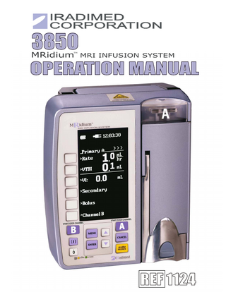
3850 MRidium MRI INFUSION SYSTEM TM
OPERATION MANUAL
REF 1124 11
MRidiumTM 3850 Infusion System Operation Manual, Part Number 1124 Release 8A, 2014-06 PER ECN 000540 © 2005-2014 Iradimed Corporation Iradimed Corporation 1025 Willa Springs Drive Winter Springs, Florida 32708 U.S.A. Tel 407-677-8022 Fax 407-677-5037 www.iradimed.com
European Authorized Representative Medical Device Consultancy 7 Pinewood Drive Ashley Heath, Market Drayton, Shropshire, UK, TF9 4PA www.medicaldeviceconsultancy.co.uk
CONTENTS Paragraph Page General Information...v Equipment Classification ...v About the Pump ... vi Warnings / Precautions ... vii User Responsibility ... xii Definitions... xii Symbols ... xiii 1.0 1.1
1.2 1.3
1.4 1.5 1.6 1.7 2.0 2.1 2.2 2.3 2.4 2.5 2.6 2.7 2.8 2.9 2.10 2.11
Introduction... 1-1 Product Description ... 1-1 1.1.1 Front of the Pump ... 1-2 1.1.2 Pump Drive Mechanism ... 1-3 1.1.3 Back of the Pump... 1-4 1.1.4 1120 MRI Power Supply ... 1-6 1.1.5 Front of the Remote Display/Charger... 1-7 1.1.6 Back of the Remote Display/Charger ... 1-8 Controls... 1-9 1.2.1 Front Panel Control Keys ... 1-9 Display ... 1-11 1.3.1 Informational Display ... 1-11 1.3.2 Infusion Parameter Setup Display ... 1-12 1.3.3 VI Display... 1-12 1.3.4 Secondary... 1-12 1.3.5 Bolus ... 1-12 1.3.6 Special Features Setup Menu... 1-12 User Interface... 1-12 System Self Test ... 1-13 Maintenance and Operator Verification... 1-13 Cleaning Instructions ... 1-13 Installation ... 2-1 Introduction... 2-1 Unpacking the Pump... 2-1 Unpacking Remote Display/Charger ... 2-1 Unpacking 3851 Channel B SideCar ... 2-1 Preparing the Pump for Use... 2-2 2.5.1 Installing Battery... 2-2 Mounting on I.V. Pole ... 2-2 Operational Checkout of the Pump... 2-2 Pump Storage ... 2-2 Remote Display Installation... 2-2 2.9.1 Charging Battery with the Remote. ... 2-3 Language Options ... 2-3 Product Structure ... 2-3
i
3.0 3.1 3.2
3.3
4.0 4.1
4.2
4.3 4.4
4.5
4.6
4.7
I.V. Set Preparation for Use... 3-1 Precautions... 3-1 I.V. Set Priming ... 3-2 3.2.1 I.V. Administration Set 1056 Priming ... 3-2 3.2.2 I.V. ByPass Set 1055 Priming ... 3-2 3.2.3 I.V. Syringe Adapter Set 1057 Priming ... 3-3 3.2.4 I.V. Extension Set 1058 Priming ... 3-3 I.V. Set Insertion and Removal... 3-4 3.3.1 Administration Set Insertion... 3-4 3.3.2 Administration Set Removal... 3-4 Pump Preparation for Use ... 4-1 Quick Setup... 4-1 4.1.1 Administration Sets... 4-1 4.1.2 Artifacts ... 4-2 Primary Configuration ... 4-2 4.2.1 Programming a Basic Infusion ... 4-3 4.2.2 Editing the Infusion Program... 4-4 4.2.3 Canceling/Pausing an Infusion ... 4-4 4.2.4 KVO (Keep Vein Open) - Infusion Complete ... 4-4 4.2.5 Volume Infused... 4-4 4.2.6 Pump Shut Down ... 4-5 4.2.7 Restoring an Infusion following Pump Power Down ... 4-5 Dual Channel Infusion ... 4-5 4.3.1 Dual Channel Infusion Setup ... 4-5 Secondary Infusion Configuration... 4-6 4.4.1 Priming a Secondary Administration Set... 4-7 4.4.2 Secondary Infusion Setup ... 4-7 4.4.3 Programming a Secondary Infusion ... 4-8 4.4.4 Viewing Primary Settings during a Secondary Infusion ... 4-8 4.4.5 Changing Primary Settings during a Secondary Infusion... 4-8 4.4.6 Stopping a Secondary Infusion and Returning to the Primary Infusion ... 4-9 4.4.7 Dual Channel Operation ... 4-9 Bolus Delivery ... 4-10 4.5.1 Bolus Setup and Start... 4-10 4.5.2 Stopping Bolus Rate Dose. ... 4-10 4.5.3 Restoring Bolus Dose. ... 4-10 Channel B ... 4-11 4.6.1 Attaching the Channel B SideCar ... 4-11 4.6.2 Detaching the Channel B SideCar ... 4-11 Special Features Menu... 4-12 4.7.1 Dose Rate Calculation ... 4-13 4.7.2 Alarm Volume ... 4-16 4.7.3 KVO Rate ... 4-16 4.7.4 Occlusion Limits... 4-16 4.7.5 Lock Keys ... 4-17 4.7.6 NEXT MENU key ... 4-17 4.7.7 Radio Channel menu... 4-17 4.7.8 Exiting the Special Features Menu ... 4-18 ii
4.8 4.9
Air Bubble Detection and Reset. ... 4-18 Data Retention ... 4-18
5.0 5.1 5.2 5.3 5.4
Alarms... 5-1 Introduction... 5-1 User Messages ... 5-1 Responding to an Alarm ... 5-1 Remote Alarms ... 5-1
6.0 6.1 6.2 6.3 6.4 6.5 6.6 6.7 6.8 6.9 6.10
Battery Operation ... 6-1 Introduction... 6-1 Inserting the Battery Pack... 6-1 Charging the Battery Pack ... 6-1 Removing the Battery Pack ... 6-2 Testing the Battery Pack ... 6-2 Battery Charge Indicator... 6-3 Battery Low Indication ... 6-3 Battery Power Gauge ... 6-4 Battery Care and Maintenance:... 6-4 Battery Pack Replacement ... 6-4
6.11
Battery Pack Related Precautions ... 6-5
Appendix A: Specifications ... A-1 Appendix B: Repair ...B-1 Appendix C: Warranty information ...C-1 Appendix D: Manufacturers Technical Declaration ... D-1 Appendix E: Troubleshooting...E-1 Appendix F: Accessories ... F-1 Appendix G: Trumpet and start up curves ... G-1 Appendix H: 1119 I.V. Pole Assemblies and Parts Descriptions... H-1
iii
FIGURES Figure Page 1-1 Front of Pump ... 1-2 1-2 Pump Drive Door Open ... 1-3 1-3 Back of Pump (Version 2) ... 1-4 1-4 Back of Pump (Original Version) ... 1-5 1-5 Model 1120 MRI Power Supply ... 1-6 1-6 Front of 3855 Remote Display/Charger... 1-7 1-7 Back of 3855 Remote Display/Charger ... 1-8 1-8 Front Panel Control Keys ... 1-9 1-9 Setup Display Screens ... 1-11 1-10 Special Features Setup Menu... 1-12 3-1 Free Flow Preventer... 3-1 3-2 Roller and Slide Clamps ... 3-1 3-3 IV Set Installation ... 3-5 4-1 Primary Pump Setup Screen ... 4-3 4-2 Dual Infusion Display ... 4-6 4-3 Secondary Infusion Set-up and Programming Screen ... 4-7 4-4 Bolus Setup Displays ... 4-9 4-5 Attaching Channel B “SideCar” ... 4-11 4-6 Special Feature Setup Menu ... 4-12 4-7 Dose Rate Calculation Menu ... 4-12 4-8 Primary Screen with Dose Rate Displayed... 4-15 4-9 Alarm Volume Adjustment Screen... 4-15 4-10 Set Comm Channel Displays ... 4-18 6-1 Battery Installation... 6-1 6-2 Battery Removal ... 6-2 6-3 Battery Test... 6-3
TABLES Table Page 5-1 Alarm, Alert and User Prompt Messages ... 5-2
iv
General Information This document provides the following directions for use: • Single channel pump that provides a full range of features in a compact, easy to use, linear peristaltic pump. • Dual channel pump offers the same features while providing two independent infusion pumps in one instrument. • The Remote Display/Charger Unit allows for remote ability to control the Pump with a total of two channels from outside the MR Scanner. The system is designed for use in the following patient care areas: • MRI (0.2 to 3T systems). • MRI/Recovery. • Pump operable and safe in up to 1 Tesla (10,000 Gauss) magnetic field. EMI Statement: This equipment generates, uses and can radiate radio frequency energy and, if not installed and used in accordance with the instructions, may cause harmful interference to other devices in the vicinity. However, there is no guarantee that interference will not occur in a particular installation. If this equipment does cause harmful interference to other devices, which can be determined by turning the equipment off and on, the user is encouraged to try to correct the interference by one or more of the following measures: 1. Reorient or relocate the receiving device. 2. Increase the separation between the equipment. 3. Connect the equipment into an outlet on a circuit different from that which the other devices(s) are connected. 4. Consult the manufacture or field service technician for help. Mains Disconnection Method: 3850 Pump: Disconnect power cord (1121) from Appliance Inlet on the side of the MRI power supply unit (1120). 3855 Remote/Charger Unit: Disconnect power cord (1128) from Appliance Inlet on the rear of the Unit. Alternate Voltage/Export: For power cord plug types see local country distributor. Unit shipped in USA with US 3 pin power NEMA plug.
3850 EQUIPMENT CLASSIFICATION Classification according to IEC 60601-1 According to the type of protection against electrical shock:
Class I equipment and internally powered
According to the degree of protection against electrical shock:
Type CF (defibrillator-proof) equipment
According to the type of protection against harmful ingress of water:
Ordinary Equipment. Complies with Section 44.4 of the Infusion Pump standard, IEC 60601-2-24.
According to the methods of sterilization or disinfection:
Non-sterilizable. Use of liquid surface disinfects only.
According to the mode of operation
Continuous operation
Equipment not suitable for use in the presence of flammable anesthetic mixture with air or with oxygen or nitrous oxide
v
About the Pump: Intended Uses Iradimed Corporation's MRidium 3850 MRI Infusion Pump/Monitoring System is intended for general hospital or clinical use by medical professionals whenever it is required to infuse patients with subcutaneous, intra-venous or intra-arterial fluids before, during, or after Magnetic Resonance Imaging (MRI) scans, functioning while either in a stationary or mobile position. The system is useful in the administration of fluids requiring precisely controlled infusion rates. The system can operate in either continuous, intermittent, or bolus delivery mode. The Infusion Pump can be used inside the MRI room mounted outside the 10,000 Gauss line (1 Tesla line), and with shielded magnets of field strength of 3.0 Tesla or less. This device is available for sale only upon the order of a physician or other related licensed medical professional, and not intended for any home use applications. Features include • Non-magnetic ultrasonic drive motor. • Special aluminium RF noise shielding enclosure. The pump is equipped with a unique battery display that provides the clinician continuous monitoring of battery capacity available. This information is displayed when the instrument is turned on. The Dual Rate Feature allows the pump to administer both primary and secondary solutions at separate flow rates and volumes. Using this feature the clinician can select and start a program for secondary delivery. Upon completion of the secondary dose, the pump can automatically switch over to a primary rate. Both channels of the MRidiumTM 3850 can be programmed for primary and secondary operation. Optional modes are easily accessed with the press of one key. The Dose Rate Calculator allows the clinician to calculate a dose rate for continuous infusion given concentration and dosage orders. The Bolus Dose feature allows the clinician to set up an initial infusion rate for a specific Bolus volume, automatically followed by a maintenance rate from the same container. An optional 2.4 GHz wireless link allows communication between the infusion pump and remote display (denoted by “R” in pump model number). Qualified service personnel can configure many features of the pump to meet specialized needs. Specific pump menu screens may vary depending on software release being used. This device is covered under one or more of the following U.S. Patents: 7,267,661 B2 and International Equivalents 7,404,809 B2 and International Equivalents 7,553,295; 7,553,882; 8,105,282 B2 7,753,882; 8,150,493; 8,690,829; 8,262,642; 8,469,932; 8,105,282; 8,500,694 EP1530440; 1802362; 4597970; 5001845 International Patents Other U.S. and International patents pending.
vi
Precautions Federal Law in the U.S.A. restricts this device to sale by or on the order of a physician. This device is intended for use by trained medical professionals only. Refer all service to Iradimed Corporation Authorized Service Representatives. The 3850 Pump has been specifically designed for operation inside an MRI Magnet Room, and is designed to operate normally in the presence of most frequently encountered electromagnetic interference in the MRI environment. Under extreme levels of interference, such as in close proximity to an electrosurgical generator, cellular telephone or a 2 way radio normal pump operation may be interrupted. Avoid use of this pump under these conditions. Use only MRI-compatible patient access devices (e.g. needles, luer-ports, etc.) to prevent any possible RF current from reaching the patient's skin. The Remote Display Charger is intended for use in the MRI control room. Do not operate the 3855 Remote Display/Charger inside the MRI Magnet Room. For safe operation, use only Iradimed Corporation recommended MRI-compatible or MRI-safe accessories. The MRI pump must be mounted securely when used in the MRI scan room. Always securely mount the pump using it’s integral pole mount clamp or other mechanical fixing means. Always secure the I.V. Pole wheel locks after positioning within the MRI Magnet Room. Avoid placing the I.V. Set adjacent to any electrical conductor within the MRI bore, which can become heated during MRI scans. The Alarm Sound Volume is adjustable for various clinical environments. Ensure the alarm sound level is appropriate for the use environment in the MRI so that it can be heard above the ambient noise level, especially during scanning. Product damage may occur unless proper care is exercised during unpacking and installation. Do not use the pump if it appears damaged in any way. The battery should be charged before use. Battery may not be fully charged upon receipt. Connect pump to AC power for at least nine (9) hours before placing the pump into use. Always connect the infusion pump power supply or Remote Display/Charger to a properly grounded 3-wire power receptacle. Never use power extension cords. If the quality of the earth grounding is in question, use battery power for the infusion pump. This equipment is not suitable for use in the presence of flammable anesthetic or other gases. Do not use this system in the presences of flammable gases. Arrange tubing, cords and cables to minimize the risk of patient or other equipment entanglement. The pump is not intended for high pressure, high viscosity radiological contrast agents. To avoid patient injury, always respond to Pump or Remote Display/Charger alarms immediately. Never leave the patient with the Pump stopped if the infusion has not been completed. To Prevent injury, avoid placement of any NIBP cuff on the limb receiving the I.V. therapy. The Pump contains materials which must be recycled, or disposed of properly. For proper disposal methods, contact your local sales representative or distributor. Hospital personnel must ensure the compatibility of the drugs as well as the performance of each pump as part of the overall infusion. Potential hazards such as drug interactions, inaccurate delivery rates, inaccurate pressure alarms and nuisance alarms may arise from other incompatibilities.
vii
Precautions (Continued) MRI pump uses medical grade silicone rubber and PVC tubing. Do not infuse pharmaceuticals or solutions that are incompatible with these materials (for example, which contain diethylhexylphthalate (DEHP)). Drugs not compatible with silicone rubber or PVC plastics, or drugs not stable under infusion conditions should not be used with this system. Consult the drug labeling to confirm drug compatibility, concentration, delivery rates and volumes are suitable for concurrent delivery, or piggyback delivery (secondary followed automatically by primary). Simultaneously infusing with more than one pump into one patient line may significantly affect the infusion rate of at least one of the pumps. This infusion pump is contraindicated for use on the inlet side of Extra Corporeal Membrane Oxygenation (ECMO) systems or anywhere the negative pressure is greater than -100 mmHg as the high negative pressure can result in uncontrolled fluid flow. Hyberbaric Chamber Operation: The MRidium system is not certified for use in oxygen enriched environments. It is not intended for use in this environment. Equipment use outside it’s specified environmental conditions can affect infusion accuracy.
Pump Related Precautions This pump is designed to stop fluid flow under alarm conditions. Periodic patient monitoring must be performed to ensure the infusion is proceeding as expected. Immediately respond to a “Close Door” alarm due to imminent lapse in infusion therapy. Immediately respond to the “Check Door” alarm as this indicates possible Free-Flow of IV Fluids. Dropping, or a severe shock to the pump, could result in damage and resultant pump inaccuracy. Refer the pump to qualified service personnel for proper checkout if either of these conditions occur. Do not place the pump into use if it fails any of the Power On Self Tests. Always verify flow rate, VTBI (Volume to be Infused) and/or dose drug entries before starting infusion. When opening the door, always check that the free flow preventer (black slide clamp) is fully pulled outward to the shut off position. If questionable Pump operation is observed, or if a System Failure occurs (i.e an unexplained continuous audible alarm with no displayed values), discontinue use of the Pump and refer it to qualified service personnel. Although unlikely, failure of certain rugged mechanical components, such as the free-flow prevention mechanism could cause fluid delivery limited to the contents of the fluid container. The maximum volume that may be infused under a single fault condition is 0.1 mL. Single fault failure of any electronic or motor control component would result in less than 0.3 mL of unexpected fluid delivery. A small amount of fluid is expelled from the set (less than 0.05 mL) under worse case conditions when the mechanical drive advances to Index each time the pump latch is opened and closed with a set loaded. If potent drugs are being used, take appropriate action to guard against overmedication of the patient. Always set the occlusion pressure alarm limit at the minimum level required for the prescribed fluid therapy. Whenever closing the Pump Door, check to make sure that nothing interferes with the pumping mechanism. viii
During a running infusion, each interruption and re-start of the infusion can add approximately 0.05 mL of delivered fluid to the indicated Volume Infused.
Pump Related Precautions (Continued) There are dangerous voltages present on internal components that may cause severe shock or death upon contact. Never open the pump casing, it’s power supply, or the Remote/Charger when connected to Mains power. Disconnect from AC power and remove battery pack prior to servicing or cleaning. Do not operate the pump on patients with the battery removed (pump will stop and not alarm during AC power loss without battery installed). Use of a properly maintained and charged battery will allow proper operation. Do not touch battery connector pins and patient simultaneously. If the Low Battery alarm sounds, connect the pump with its power supply to AC power immediately. Replace blown fuses on the 1120 Pump MRI power supply or Remote Display/Charger with fuses of the same type and rating only, or a fire hazard could exist. Never use sharp objects (paper clips, needles, etc.) to clean any part of the pump. Keep the pump door latch securely closed when the pump is not in use. This will avoid door latch damage. Do not sterilize the pump or any component by heat, steam, ethylene oxide (ETO), or radiation. The screen displays the VTBI (Volume to be Infused) in whole integers above 99.9. Any fraction of a milliliter delivered is not displayed, but is retained in memory. To avoid damage to the I.V. Pump and Pole, always move the I.V. Pole separately from the patient trolley to prevent accidental entanglement. The pump body is made of aluminum and is non-magnetic. However, when moving the pump within high magnetic fields (>2000 gauss) one might notice Eddy Current effects. These are forces generated in the aluminum which resists motion through the intense magnetic field. Such effects are normal and present no risk of free magnetic movement of the unit.
Set Related Precautions Always use aseptic techniques. Patient infection could result from mishandled or non-sterile assemblies. Use only Iradimed Corporation MRidiumTM 1000 Series administration sets. The use of other sets will cause improper pump operation resulting in inaccurate fluid delivery. MRidiumTM 1000 Series administration sets are only intended to be used with the MRidiumTM Pump. All infusion administration sets are supplied sterile and are single use only. Do not sterilize or reuse. Prior to use of any Infusion Set, examine the pouch and inspect for damage that could compromise sterility. If the pouch or Set is damaged, discard and use another Set. Administration sets should be changed per the Center for Disease Control (CDC) guidelines or healthcare provider policy. Discard after use. Design use life of I.V. sets is six (6) hours maximum. Disconnect the I.V. line from the patient before starting the priming procedure. Prepare the primary solution container in accordance with the manufacturer’s instructions.
ix
The use of positive displacement infusion devices ported together with gravity flow infusion systems into a common I.V. site may impede the flow of the gravity flow system and affect their performance. Hospital personnel must ensure that the performance of the common I.V. site is satisfactory under these conditions.
Set Related Precautions (Continued) Interconnection with I.V. sets with small inner diameter may affect pump accuracy at high flow rates. Avoid interconnection with small bore diameter I.V. sets (less than 0.050 inch I.V. tubing) if high flow rates are used. A kinked or occluded I.V. line could cause the pump to operate abnormally and affect the accuracy of the infusion. Before operating this system, verify that the I.V. line is not kinked or occluded. To avoid nuisance alarms, confirm that the fluid source is positioned higher than the pump. Setting the primary rate greater than the secondary rate will result in a more rapid infusion of any residual secondary drug remaining in the line, the administration set, and fluid container. When performing a secondary infusion: • Secondary solution container must be higher than the primary solution container. • The Secondary VTBI (Volume to be Infused) setting must be equal to the volume in the secondary container. This requires consideration of such variables as factory overfill, medication additions, etc. Underestimating the volume will cause the remaining secondary solution to be infused at the primary rate; overestimating will result in the primary solution being infused at the secondary rate. Multiple doses from a single container are not possible. Air bubbles may form distal to the pump as a result of normal out-gassing of dissolved air in the fluid. This may occur if a chilled solution is being used, if the pump is mounted significantly above the patient, or with certain fluids known to routinely outgas. In these cases, an air eliminating filter may be required. During a prolonged infusion, routinely inspect I.V. Set, access device and patient line assemblies for proper attachment and orientation. Variations of head height, back pressure, selected catheter type, or any combination of these may affect rate accuracy. Factors that can influence back pressure are: I.V. set configuration, I.V. solution viscosity and I.V. solution temperature. Back pressure may also be affected by catheter type. The use of pumping infusion devices ported together with gravity flow infusion systems into a common IV site (primary IV set with secondary IV lines) can affect the accuracy of the gravity flow systems, and result in unintended flow rates from these gravity systems. Always ensure the common IV site is acceptable for use under these conditions. Reference to specific drugs and default parameters are provided for the user’s convenience. Always refer to the specific drug product labeling for information concerning appropriate administration techniques and dosages.
x
Battery Pack Related Precautions The 1133 Battery Pack contains several lithium-polymer cells and an integral safety circuit. As these cells age, they can expand due to internal gas release, which is anticipated for this type of cell. However, if excessive expansion occurs, this can result in the battery case expanding (swelling), and possibly cause failure of the battery case, cells, or safety circuit. If this is observed, remove the Battery Pack from use and replace it as soon as possible. The 1133 Battery Pack contains protective circuitry to prevent catastrophic battery failure. If the Battery pack is damaged, this protective circuitry may not prevent battery failure. Remove the Battery Pack from use if the Pack becomes damaged, or the potential for Battery Pack damage is suspected. Do not use a damaged or swollen 1133 Battery Pack. Avoid damage to the 1133 Battery Pack by impact, dropping, overheating, or mechanical abuse. Never compress, drop, shock, or strike the 1133 Battery Pack. Never use objects that could puncture the internal battery cells. Any of these actions can cause the battery cells to heat, smoke, or cause catastrophic battery failure, which could result in fire. Do not attempt to disassemble the 1133 Battery Pack. Damage caused by disassembly or tool use can result in catastrophic battery failure, which could result in fire. If the 1133 Battery Pack case begins to expand and/or swell, discontinue battery charging and use immediately, and replace the Battery Pack. Continued charging will cause further Battery Pack case expansion, with possible battery case fracture, and potential electrolyte leakage. If the 1133 Battery Pack becomes damaged, avoid contact with the battery cell electrolyte. If the electrolyte contacts the skin or eyes, seek medical attention immediately. If the 1133 Battery Pack shows sign of the battery case expanding (swelling), remove the Battery Pack from use and replace it as soon as possible. In extreme conditions, this swelling can cause the 1133 Battery Pack to become jammed or stuck within the 3850 Pump or 3855 Remote Display, and/or cause the Battery Pack plastic case to burst open. If this occurs, do not use tools that could cause damage to the internal battery cells. Refer to the 1125 Service Manual for removal under these conditions. Under no circumstances should Battery Packs or the internal cells be incinerated as this can cause an explosion.
xi
User Responsibility This product will perform in conformity with the description contained in this users manual and accompanying labels, inserts, etc., when assembled, operated, maintained and repaired in accordance with the instructions provided. This product must be checked and calibrated periodically. A malfunctioning product should not be used. Parts that are broken, missing, plainly worn, distorted or contaminated should be replaced immediately. Should such repair or replacement become necessary, refer unit to Iradimed Corporation qualified service personnel. This product or any of its parts should not be repaired other than in accordance with written instructions provided by the manufacturer, or altered without written approval of Iradimed Corporation. The user of the product has the sole responsibility for any malfunction which results from improper use, faulty maintenance, improper repair, damage or alteration by anyone other than Iradimed Corporation or Iradimed Corporation authorized service personnel.
Using This Manual Read this manual completely before attempting to use the pump. Warning, Cautions and Notes. This manual contains three levels of precautionary information. • A Warning alerts the user that there is a possibility of injury or death to a human being. • A Caution alerts the user that there is a possibility of damage to equipment. • A Note contains essential information deemed especially important by Iradimed Corporation.
Definitions Channel A Channel B hr. KVO mL Primary Rate Secondary VI VTBI
The designation for the first infusion channel. All pumps contain at least one linear peristaltic pump head for one infusion line. The designation for the second infusion channel. The second infusion pump head is optional and some pumps may not contain it. hour. Keep-Vein-Open. milliliter. Main Infusant for the prescribed I.V. therapy. The infusion settings that are implemented after any secondary infusion sequence is complete. Infusion rate in mL / hr. The first infusion settings to be implemented in an infusion sequence. Sometimes referred to as “piggyback.” Volume Infused in mL. Volume To Be Infused in mL.
xii
Symbols Attention: Consult Accompanying Documents, or alternately, Caution.
Appropriate for use in MR environment
Defibrillator Proof
MR Conditional. Only appropriate for use in MR environment with manufacturer’s defined restrictions.
Type CF Applied Part Date of Manufacture
MR Unsafe. Not appropriate for use in MR environment (i.e. inside the MR magnet room)
Indicates that the device conforms to the Medical Device Directive
Single Use Only
Direct Current
Product Serial Number
Product is Latex-free
Alternating Current
Drops per millimeter specification for I.V. Set is identified on Drop Symbol
Do not Resterilize
Lot or batch code for I.V. Set will be identified near Lot Symbol
Product Part Number
Approximate Set priming volume
Expiration date for I.V set will be identified near hour glass symbol
Main Battery Capacity. (X inside Icon denotes no battery installed.)
Denotes I.V. Set was sterilized with Irradiation
AC Power is connected to 100-240 VAC
Contains Lithium. Requires proper disposal/recycling of this material.
Secondary Infusion Mode
Power On, or On
Volume to be Infused
Power Off, or Off
Caution: Federal (U.S.A.) law restricts this device to sale by or on the order of a physician
Volume Infused
Maximum rated load is 20 Kg.
Input/output connection. Allows data communication.
Input Connection Only
Do not discard. Contact recycler for proper disposal.
Output Connection Only
xiii
>>>
Spare Battery Capacity. (X inside Icon denotes no battery installed.)
Storage Temperature Range
EC Authorized Representative
2.4 GHz Radio is communicating.
Radio-Frequency transmission source Keep equipment below this line on the 1119 IV Pole.
Telecommunications Alert Symbol Class 2 (European Union Countries only)
Do not use if package is damaged
Sterile Fluid Path
Keep equipment below this line on the 1119 IV Pole.
Replace Fuse with 1 Amp, 3AG, 250V time delay (Slow Blow) fuse.
Alternating symbols indicate Channel A is infusing
<<<
Alternating symbols indicate Channel B is infusing
Refer to operating instructions for important safety information.
STBY
Infusion has been paused. Press start to resume infusion
2.4 GHz Radio Antenna
This product has been certified to UL60601-1 and applicable Particular Standard IEC 60601-2-24, for which the product has been found to comply by Underwriters Laboratories Inc.
This product has been certified to UL60601-1 and applicable Particular Standard IEC 60601-2-24, for which the product has been found to comply by Intertek.
xiv
SECTION 1 INTRODUCTION 1.0 Introduction. The MRidiumTM 3850 MRI Infusion System is intended for patients that require medications and/or fluids during an MRI scan. This pump is designed to provide infusion therapy at all stages of the MRI procedure. This system is for use by trained medical personnel only and is not intended for long term patient care outside of an MRI environment. This system provides the following features: • Continuous Infusion, Dose Rate Calculation Program and Automatic Bolus. • Automatic free-flow protection for the I.V. line. • Up to two channel fluid delivery, each with separate primary/secondary programmable rate and VTBI, into single or separate IV lines. • Rechargeable long life battery. Lasts up to 12 hours at 125 mL/hr. • Status indicator light above door (Red for Alarm, Green for Infusing). • Soft keys to program various functions. • Large LCD display screen. • Up and Down arrow control keys to change numeric values quickly and easily. • Handle for easy portability, weighs less than 11.5 pounds. • I/O port. • Optional second channel with the addition of the 3851 SideCarTM. • Optional remote control with the additional 3855 Remote Display/Charger. • Memory card slot for easy upgrades.
CAUTION: Handle the MRidiumTM 3850 MRI Infusion Pump and additional channels with care. If it should be dropped or severely jarred, it should be immediately taken out of service and inspected by a qualified biomedical technician. 1.1 Product Description. The MRidiumTM 3850 MRI Infusion System is designed for operation in the MRI environment and may be used on the patient near the MRI magnet (up to the 1.0 Tesla or 10,000 Gauss Line). Operating on battery power, when fully charged this system will provide up to 12 hours of operation at an infusion rate of up to 125 mL/hr and at least four (4) hours at rates up to 999 mL/hr. The MRidium Wireless Remote Display allows for remote ability to control the Model 3850 MRidium MRI Infusion Pump with a total of two channels from outside the MR Scanner. It utilizes the same user interface as the infusion pumps and will allow adjustment of all pump parameters, rates, titration, volume to be infused, starts, stops, and resetting alarms. The large clear display shows all pump information at your desk top from the control room. The Wireless remote also acts as a charger for a backup or spare battery pack for the 3850 MRidium MRI Infusion Pump. It utilizes a wireless link at 2.4 GHz for easy installation with no image artifacts. The 3850R designates a 3850 Pump with the optional 2.4 GHz wireless link for communication with the 3855 Remote Display. NOTE: The Remote Display/Charger only operates on AC Mains Power. This unit does not operate on battery power. This unit does not sound a Low Battery alarm for the Spare Battery being charged.
1-1
1.1.1 Front of the Pump. See Figure 1-1 for the location of the major components on the front of the pump. a. Handle. Located on the top of the pump, the handle provides for easy transportation of the pump from location to another. b. Main Display. Provides a visual display of all the parameters and features of the pump. c. Run/Alarm Lamp. Provides a visual display of the pumps operating condition. d. Battery. Located behind a door on the back of the pump, the battery provides for power in the absence of a hospital grade AC Mains outlet. e. Pump Area EZ-Latch Door. Pressing down on this button and lifting this handle unlatches the door protecting the pumping mechanism and infusion line. f. Main Control Keypad. Provides control of the various features of the pump. g. Soft keys. Provides a way to adjust the configuration of the pump. h. AC Power/Battery Charge LED. Provides indication that MRI power supply is connected and AC power is applied to Charge the pump battery
Figure 1-1. Front of Pump
1-2
1.1.2 Pump Drive Mechanism. See Figure 1-2 for location of the major components of the infusion system pump drive mechanism.
Figure 1-2. Pump Drive Door Open a. b. c. d.
e.
Upper and Lower I.V. Set Snap-In Port. Provides for a secure mounting of the I.V. set for infusion. Linear Peristaltic Pump Drive Mechanism. Provides for the positive movement of fluids through the infusion line. Bubble Detector. Provides for the detection of air bubbles in the infusion line. Free-Flow Detector Switch. Located internally in the pump’s lower snap-in port the IV Set Free-Flow Detector Switch detects when IV set is properly installed and functioning. Inlet and Outlet Pressure Sensors. Provide infusion line pressure measurements for pressure monitoring and alarms.
NOTE: After attachment of the 3851 SidecarTM module (Refer to Section 4.6), the operation of Channel B SidecarTM pump drive mechanism is identical to the main pump drive. The only difference is that the Channel B door opens to the left side, which is opposite that of the main pump door.
1-3
1.1.3 Back of the Pump. See Figure 1-3 (Figure 1-4) for the location of the major components on the back of the pump. a. Handle. Provides for easy transportation of the pump from location to another. b. Optional Secondary Pump Drive Electrical Connector. Provides for the addition of a Channel B pump mechanism. c. I.V. Pole Clamp. Provides a secure mounting of the pump to the I.V. pole. d. Audible Speaker. Provides the audible sounds for alarms and alerts. e. 2.4 GHz Antenna Connector. Used to connect Antenna for Remote Display/ Charger Option (3850R only). f. Power Input. Provides for connection to the AC Power Adapter to run the pump on hospital grade AC Mains power. Connect only model 1120 MRI Power Supply.
Figure 1-3. Back of Pump (Version 2) (Serial Number IR5010778 and above)
1-4