Guide
6 Pages
Preview
Page 1
3880 Wireless Application Guide Pre Work: Check Software Compatibility 1.1. Prior to troubleshooting, ensure all components including internal and external radios are on the same and preferably latest software revision. 1.2. Have all components on the same wireless channel. 1.3. When there are multiple 3886 Multi-Gas module being used, it may be optimal to assign a unique wireless channels to them to support patient workflows. 1.4. Ensure the Tablet link power is set to Low. 1.5. Ensure the Monitor link lower is set to High or Medium.
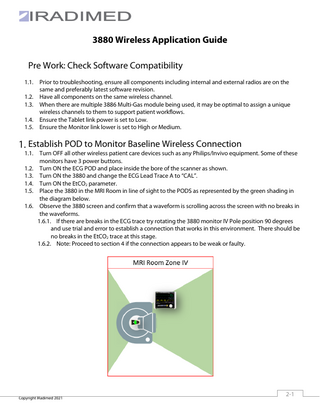
Establish POD to Monitor Baseline Wireless Connection 1.1. Turn OFF all other wireless patient care devices such as any Philips/Invivo equipment. Some of these monitors have 3 power buttons. 1.2. Turn ON the ECG POD and place inside the bore of the scanner as shown. 1.3. Turn ON the 3880 and change the ECG Lead Trace A to “CAL”. 1.4. Turn ON the EtCO2 parameter. 1.5. Place the 3880 in the MRI Room in line of sight to the PODS as represented by the green shading in the diagram below. 1.6. Observe the 3880 screen and confirm that a waveform is scrolling across the screen with no breaks in the waveforms. 1.6.1. If there are breaks in the ECG trace try rotating the 3880 monitor IV Pole position 90 degrees and use trial and error to establish a connection that works in this environment. There should be no breaks in the EtCO2 trace at this stage. 1.6.2. Note: Proceed to section 4 if the connection appears to be weak or faulty.
Copyright IRadimed 2021
2-1
Establish Monitor to Base Station Baseline Wireless Connection
2.1. Check Antennas are firmly secured to the correct receptacle on the rear of the Base Station. 2.2. Check that the directional “high gain” antenna is positioned so that the 3880 monitoring location is in the antennas field of view. 2.2.1. For best performance, position the Base Station as far away from the high gain antenna as possible (minimum of 3 feet / 1 meter) and that there are no large obstructions in between the high gain antenna and the 3880 as shown. 2.2.2. Note: Longer antenna cables are available by contacting IRradimed Customer Service.
2.3. Shut and seal the MRI room door. 2.4. Turn ON the Base Station and Tablet 2.5. Observe the wireless signal indicator on the top left of the tablet. Acceptable signal strength is represented by 4 or 5 bars as shown. If less than 4 bars are observed, proceed to Section 5.
2.6. Observe the ECG waveform and the EtCO2 yellow line. If breaks are noticed in the ECG Waveform and the EtCO2 is solid yellow line then there is most likely drop out between the POD and the Monitor. Proceed to Section 4.
2.6.1. If breaks are noticed in both the EtCO2 and ECG waveforms then there is most likely drop out between the Monitor and the Base Station. Proceed to Section 5.
Copyright IRadimed 2021
2-2
Optional Step: Check Tablet to Base Station COM Limits Some applications and workflows will be optimized when the Tablet is located in a different position from the base station in Zone III.
3.1. Follow Steps 1 and 2 and ensure no drop out is noticed. 3.2. Turn on all equipment and place the 3880 in simulation mode. 3.3. Move the tablet to the desired location and observe the color of the wireless signal indicator. Acceptable signal indicator is represented as a green color as shown. If the indicators are yellow or red then slowly move the tablet location until the indicator turns green. Document the limit.
Acceptable Tablet to Base Signal
Wireless Signal Dropout Possible
3.4. Once the wireless indicator is stable on green observe the waveforms on the table and ensure no breaks in the waveforms are observed. 3.4.1. If drop out is observed try printing a paper strip. If the printed strip shows gaps in the traces then the drop out is between the Monitor and the Base Station. Proceed to Step 5. 3.4.2. If the printed strip is correct and the tablet has gaps in the waveform then there is drop out between the Base Station and the Tablet. Try a different location or Tablet Link Power. Note: Raise Tablet power with caution. Higher Tablet link power can contribute to drop out of other wireless devices. Follow Steps 1 and 2 after Tablet link power changes.
Copyright IRadimed 2021
3-3
Troubleshooting: Pod to Monitor Dropout
4.1. Ensure POD is not in contact with an ECG Coil or touching the MRI Bore surface. 4.2. Ensure that the POD antenna is not directly touching any part of the patient’s body. NOTE: The Antenna is positioned in the bottom of the POD as highlighted in red in the diagram. 4.2.1. Use a 1190 POD Jacket or place a towel between the POD and the patient’s body to add separation space and to limit the patient’s body from absorbing the RF signal.
4.3. Rotate the POD a few degrees to find a position where communication is established and reliable.
4.4. Rotate the 3880 a few degrees to find a position where COM can be established. 4.5. Switch wireless channels and repeat steps again. 4.6. If drop out continues proceed to section 5. Copyright IRadimed 2021
4-4
Troubleshooting: Monitor to Base Station Dropout 5.1. Place the 3880 in Simulation mode. 5.2. Turn ON the Base Station and Tablet and establish communication. 5.3. Confirm: 5.3.1. That all antenna connections are firmly secure to the right socket. 5.3.2. That the High-Gain Antenna is facing the Zone IV location where the monitor is located. 5.4. Once a troubleshooting option improves the wireless communication. Run an MRI Scan with the 3880 in simulation mode and observe the wireless performance. If drop out is observed with the MRI RF flooding the room continue to the next troubleshooting option. Troubleshooting Option 1: Adjust Wireless Channels 5.5. Try an alternate Radio Channel combinations from 1 through 8. 5.5.1. If dropout is still witnessed proceed to Option 2. Troubleshooting Option 2: Adjust Monitor Link Power 5.6. If available, increase the Monitor link power to Medium or High depending on the specific build of your device. 5.6.1. If dropout is still witnessed proceed to Option 3. Troubleshooting Option 3: Use Higher Gain Antenna to Boost DB 5.7. Swap the high gain antenna with the IRadimed directional high gain antenna part number 1195. 5.7.1. If dropout is still witnessed proceed to Option 4.
Troubleshooting Option 4: Search Zone IV acceptable Wireless Zone (easy) 5.8. Slowly move and rotate the 3880 around zone IV and observe the wireless signal indicator and stop when you find a location that supports 4 or 5 bars of signal strength. Document this location.
Copyright IRadimed 2021
5-5
Troubleshooting Option 5: Search Zone IV acceptable Wireless Zone (Precise) 5.9. If Drop out is witnessed open up the Radio Test service menu and make a note of the lost packet count rate of change as shown:
5.10. Search for a location inside the MRI Room that is compatible with wireless communication. 5.10.1. Slowly rotate the 3880 while observing for a reduction in the Lost Packets Rate of change. 5.10.2. Slowly Move the 3880 around the MRI Room while observing for a reduction in the Lost Packets Rate of change. A slowly counting number of lost packets is typical. i.e. 10-20 counts over a 30 second period is ok. 5.10.3. Note: If the lost packets area is grayed out then there is complete COM loss.
Troubleshooting Option 5: Install Zone IV Room Antenna 5.11. If none of the options above improve wireless communication contact Iradimed Technical Support as a hardwired Zone IV Antenna might need to be installed for this application. Potential Information needed for a phone call with Technical Support. • Iradimed 3880 Serial Number. • Distance from Iradimed Base Station to the Penetration Panel including any vertical and horizontal distances. • Image of MRI penetration panel showing available connectors may be needed.
Copyright IRadimed 2021
5-6