User Manual
36 Pages
Preview
Page 1
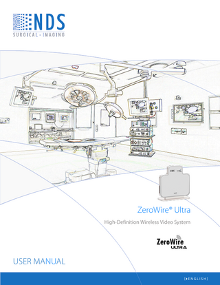
ZeroWire® Ultra High-Definition Wireless Video System
User manual [ English]
© 2013 NDS Surgical Imaging, LLC. All rights reserved. Information in this document has been carefully checked for accuracy; however, no guarantee is given to the correctness of the contents. This document is subject to change without notice. NDSsi provides this information as reference only. Reference to products from other vendors does not imply any recommendation or endorsement. This document contains proprietary information protected by copyright. No part of this manual may be reproduced by any mechanical, electronic, or other means, in any form, without prior written permission of NDSsi. All trademarks are the property of their respective owners.
Table of Contents Tab 1 Warnings and Cautions------------------------------------------------------------------------------ ii Recycling ------------------------------------------------------------------------------------------------ ii Declarations of Conformity ------------------------------------------------------------------------iii Legal Statement ---------------------------------------------------------------------------------------iii Tab 2 About This Manual------------------------------------------------------------------------------------ 1 Intended Use and Contraindications ------------------------------------------------------------ 1 Overview------------------------------------------------------------------------------------------------- 1 Tab 3 Connector Panels-------------------------------------------------------------------------------------- 2 Installation ---------------------------------------------------------------------------------------------- 3 Power Options ----------------------------------------------------------------------------------------- 6 Wiring Diagrams--------------------------------------------------------------------------------------- 7 Cable Bend Radius ------------------------------------------------------------------------------------ 7 Setup------------------------------------------------------------------------------------------------------ 8 Typical Installation ------------------------------------------------------------------------------------ 9 All Channels In Use Indication--------------------------------------------------------------------- 9 Performance -------------------------------------------------------------------------------------------- 9 Positioning and Orientation --------------------------------------------------------------------- 10 Non Line of Sight Operation --------------------------------------------------------------------- 13 Avoiding Co-Channel Interference------------------------------------------------------------- 14 Advanced Features --------------------------------------------------------------------------------- 15 Channel Usage --------------------------------------------------------------------------------------- 16 Multi System Installation-------------------------------------------------------------------------- 16 Signal Strength -------------------------------------------------------------------------------------- 16 Tab 4 Troubleshooting ------------------------------------------------------------------------------------ 17 Tab 5 Drawings and Dimensions ----------------------------------------------------------------------- 18 Tab 6 Specifications ---------------------------------------------------------------------------------------- 19 Supported Video Modes ------------------------------------------------------------------------- 20 Optional Accessories ------------------------------------------------------------------------------ 21 Optional Accessory Kits --------------------------------------------------------------------------- 21 Cleaning and Disinfecting instructions ------------------------------------------------------- 22 Tab 7 Electromagnetic Compatibility (EMC) Tables ----------------------------------------------- 23 Contact---------------------------------------------------------------------------------------------- Back
i
1
Warnings and Cautions This symbol alerts the user that important information regarding the installation and / or operation of this equipment follows. Information preceded by this symbol should be read carefully in order to avoid damaging the equipment. This symbol warns user that un-insulated voltage within the unit may have sufficient magnitude to cause electrical shock. Therefore, it is dangerous to make contact with any part inside the unit. To reduce the risk of electric shock, DO NOT remove cover (or back). There are no user serviceable parts inside. Refer servicing to qualified service personnel. This symbol cautions the user that important information regarding the operation and / or maintenance of this equipment has been included. Information preceded by this symbol should be read carefully to avoid damage to the equipment. This symbol denotes the manufacturer. This symbol denotes the manufacturer’s European Community representative. To prevent fire or shock hazards, do not expose this unit to rain or moisture. Also, do not use this unit's polarized plug with an extension cord receptacle or other outlets unless the prongs can be fully inserted. The product is designed to meet the medical safety requirements for a patient vicinity device. This product is a Class II medical device. No modifications are allowed. This equipment/system is intended for use by healthcare professionals only. Safety Compliance: This device is T.U.V. approved with respect to electric shock, fire and mechanical hazards only in accordance with CAN/CSA C22.2 No. 60601-1 and ANSI/AAMI ES60601-1.
0673
Safety Compliance: This device meets the requirements of EN60601-1 so as to conform to the Medical Device Directive 93/42/EEC and 2007/47/EC (general safety information). Radio Approval: This device meets the requirements of EN 302 065 V1.2.1 and conforms to Radio and Telecommunications Terminal Equipment (R&TTE) Directive 1999/5/EC. FCC Identification: UEZTZM7201
This product complies to the above standards only when used with the supplied medical grade power supply. Power Supply: Ault MW172KB2400F02 or Ault MW172KB2400B02 AC Input: 100 to 240 Volts at 50 to 60 Hz. DC Output: 24 volts at 0.75 amps Power Cord: Use a hospital grade power cord with the correct plug for your power source. Disconnect the power cord from the AC mains. The power cord is the only recognized disconnect device. The MEDICAL EQUIPMENT should be positioned so that its disconnect device is readily accessible. The device should be powered from a center tapped circuit when used in the US at voltages over 120 volts. This product is intended for continuous operation. Recycling: Follow local governing ordinances and recycling plans regarding the recycling or disposal of this equipment.
ii
Declarations of Conformity FCC and Council Directives of European Standards: This device complies with Part 15 of FCC rules and 93/42/EEC and 2007/47/EC of the Council Directives of European Standards. Operation is subject to the following two conditions: (1) This device may not cause harmful interference, and (2) this device must accept any interference received, including interference that may cause undesirable results. 1. Use the attached specified cables with the device so as not to interfere with radio and television reception. Use of other cable and adapters may cause interference with other electronic equipment. 2. This equipment has been tested and found to comply with the limits pursuant to FCC part 15 and CISPR 11under clause 3.1 and 8.5. This equipment generates, uses and can radiate radio frequency energy and, if not installed and used in accordance with the instructions, may cause harmful interference to radio communications. IEC: This equipment has been tested and found to comply with the limits for medical devices to the IEC 60601-1-2. These limits are designed to provide reasonable protection against harmful interference in a typical medical installation. This equipment generates, uses and can radiate radio frequency energy and, if not installed and used in accordance with the instructions, may cause harmful interference to other devices in the vicinity. FCC, Council Directives of European Standards and IEC: There is no guarantee that interference will not occur in a particular installation. If this equipment does cause harmful interference to radio or television reception, which can be determined by turning the equipment off and on, the user is encouraged to try to correct the interference by one or more of the following measures: Reorient or relocate the transmitter and / or the receiver. Increase the separation between the equipment and receiver. Connect the equipment into an outlet on a circuit different from that to which the receiver is connected. Consult your dealer or an experienced radio/TV technician for help. Accessory equipment connected to this device must be certified according to the respective IEC Standards, i.e. IEC 60950-1, for data processing equipment and IEC 60601-1 for medical equipment. Furthermore, all configurations shall comply with the system standard, IEC 60601-1-1. Anyone who connects additional equipment to the signal input part or signal output part configures a medical system, and is therefore responsible that the system complies with the requirements of system standard IEC 60601-1-1. Whoever is responsible for securing the device to a system needs to insure that the mounting equipment used with this device complies to IEC standard 60601-1. If in doubt, consult with your vendor’s technical service department.
Legal Statement NDS sells its products through other medical device manufacturers, distributors and resellers and therefore, purchasers of this NDS product should consult with the entity through which this product was originally purchased regarding the terms of any applicable product warranties provided by such entity, if any. NDS neither assumes nor authorizes any person to assume for it any other liabilities in conjunction with and/or related to the sale and/or use of its products. To ensure proper use, handling and care of NDS products, customers should consult the product specific literature, instruction manual, and/or labeling included with the product or otherwise available. Customers are cautioned that system configuration, software, the application, customer data and operator control of the system, among other factors, affect the product’s performance. While NDS products are considered to be compatible with many systems, specific functional implementation by customers may vary. Therefore, suitability of a product for a specific purpose or application must be determined by the consumer and is not warranted by NDS. NDS SPECIFICALLY DISCLAIMS ALL WARRANTIES OF ANY KIND, WHETHER EXPRESS, IMPLIED AND/OR STATUTORY, INCLUDING, BUT NOT LIMITED TO WARRANTIES OF MERCHANTABILITY, FITNESS AND/OR OF SUITABILITY FOR A PARTICULAR PURPOSE, AND NON-INFRINGEMENT WITH RESPECT TO ALL NDS PRODUCTS OR SERVICES. ANY AND ALL OTHER WARRANTIES, REPRESENTATIONS AND/OR GUARANTEES, OF ANY TYPE, NATURE OR EXTENT, BE IT IMPLIED, EXPRESS AND/OR WHETHER ARISING UNDER OR AS A RESULT OF ANY STATUTE, LAW, COMMERCIAL USAGE, CUSTOM, TRADE OR OTHERWISE, ARE HEREBY EXPRESSLY EXCLUDED AND DISCLAIMED. NDS, its suppliers and/or distributors are not liable, directly or by way of indemnity for any special, incidental, consequential, punitive, exemplary or indirect damages, including but not limited to alleged damages for delayed shipment, non-delivery, product failure, product design or production, inability to use such products or services, loss of future business (lost profits), or from any other cause, whatsoever, in connection with or arising from the purchase, sale, lease, rental, installation or use of such NDS products, these terms and conditions, or with respect to any the terms of any agreement which incorporates these terms and conditions. SOME JURISDICTIONS DO NOT ALLOW EXCLUSIONS AND DISCLAIMERS OF CERTAIN WARRANTIES OR LIMITATIONS OF LIABILITY, SO THE LIMITATIONS AND/OR EXCLUSIONS, SET FORTH HEREIN, MAY NOT APPLY. IN THAT EVENT LIABILITY WILL BE LIMITED TO THE GREATEST EXTENT PERMITTED BY LAW IN THE SUBJECT JURISDICTION. The information provided in this document, including all designs and related materials, is the valuable property of NDS and / or its licensors and, as appropriate, they reserve all patent, copyright, and other proprietary rights to this document, including all design, manufacturing reproduction, use, and sales rights thereto, except to the extent said rights are expressly granted to others.
iii
About This Manual This manual is designed to assist the user with installation, setup and operation of the NDS ZeroWire® Ultra HD wireless video system.
2
A numbered tab on the side of the page denotes the beginning of a section. The functional descriptions in this manual are representative of: Part Numbers: 90T2036 = ZeroWire Ultra Receiver 90T2037 = ZeroWire Ultra Transmitter (Input: DVI ) 90T0039 = ZeroWire Ultra Transmitter (Input: DVI and 3G-SDI) Manual Part Number: 60G0535 Rev A
Intended Use and Contraindications The NDSsi ZeroWire Ultra HD Wireless Video System is a paired transmitter and receiver, intended for delivery of video signals over a radio-frequency link to a video display during endoscopic and general surgical procedures. The ZeroWire Ultra HD Wireless Video System is a non-sterile reusable device not intended for use in the sterile field. It is intended for use by qualified physicians having complete knowledge of these surgical procedures. Contraindications: 1. These units are non-sterile reusable devices and are not intended for use within a sterile field. 2. This equipment may not be used in the presence of flammable anesthetics mixture with air, oxygen or nitrous oxide. No part of this product may come in contact with a patient. Never touch the product and a patient at the same time. For mission critical applications, we strongly recommend that a replacement ZeroWire Ultra transmitter and receiver pair, and a DVI cable be immediately available. Additionally, we recommend that a display that is hard wired to the video source be immediately available whenever a surgical procedure is in progress. See typical installation drawing on page 9.
Overview The ZeroWire Ultra transmitter and receiver pair allows wireless delivery of video signals from the DVI or 3G-SDI output of an endoscopic camera processor or other video source to the DVI input of a video display. It operates as an unlicensed ultra-wideband (UWB) wireless system in compliance with FCC (Part 15) rules governing UWB. The system is composed of a transmitter (Tx) and a receiver (Rx) pair. The Tx unit is designed to be mounted on the rear top edge of a display on a surgical cart, or on the cart itself. The transmitter may obtain its input video signal from either an endoscopic camera processor or the display’s re-drive output. The Tx unit is powered from the provided 24 VDC power supply (“wall-wart”) or through the optional ‘Y’ adapter cable*. The ‘Y’ adapter cable is described on page 6. The Rx unit is designed to be mounted on the rear top edge of a display, it may also be mounted on a cart, and is powered from the provided 24 VDC power supply (“wall-wart”) or through the optional ‘Y’ adapter cable*. The ‘Y’ adapter cable is described on page 6. A typical installation is shown on page 9. *Note: The ‘Y’ adapter cables are for use with displays that are powered by 24 VDC and whose power connector accepts one of the J2 connectors shown on page 6. 1
Connector Panels
ZeroWire Ultra Transmitter (Tx)
ZeroWire Ultra Receiver (Rx)
3
3G– SDI input (90T2016 only)
DVI input
DVI output
Power connector
Tx & Rx Common Connectors
The USB port is used for installing updates to the Tx or Rx firmware. It is not a general purpose I/O port
The BOND button allows the bonding of a transmitter to a receiver. On the Tx the BOND button is used to wake the unit from Deep Sleep. See page 15. On the Rx the BOND button is used to activate the Signal Strength bar. See page 16. 2
Installation The only mounting bracket included with the ZeroWire Ultra is the Desktop mount. All other brackets are sold separately. Desktop: With the side stamped FRONT and the black surface of a ZeroWire Ultra Rx or Tx module facing you, insert the desktop mount into the slot in the bottom of the module and push downwards on the mount until the module seats.
Install with this side facing the side with the ZeroWire Ultra logo printed on it.
Optional Mounting Brackets: Extended Height Bracket for 24” and 26” Radiance Displays: Each step bracket is stamped with a part number (P/N). For Radiance 24” and 26” displays, select the extended height step bracket P/N 20C0669 . Replace the left hand mounting screws with 2 of the provided mounting screws. Do not tighten them. Remove the two right hand screws from the VESA mount . With the side stamped FRONT facing the front of the display, slide the step bracket between the VESA mount and the back of the display until notches labeled for the display you are working with fit over the two left hand screws. Replace the right hand screws with the screws provided and tighten all screws. With the black surface of a ZeroWire Ultra Rx or Tx module facing the front of the display, align the slot on the bottom of the module with the top of the bracket and push the module down on the bracket until the module seats. Figure 1 shows the completed assembly. Figure 1 This side faces the front of the display.
3
19” and 23” Radiance and 24” EndoVue Display: Each step bracket is stamped with a part number (P/N). For Radiance 19” and 23” and EndoVue 24” displays, select step bracket P/N 20C0660. Replace the left hand mounting screws with 2 of the provided mounting screws. Do not tighten them. Remove the two right hand screws from the VESA mount . With the side stamped FRONT facing the front of the display, slide the step bracket between the VESA mount and the back of the display until notches labeled for the display you are working with fit over the two left hand screws. Replace the right hand screws with the screws provided and tighten all screws. With the black surface of a ZeroWire Ultra Rx or Tx module facing the front of the display, align the slot on the bottom of the module with the top of the bracket and push the module down on the bracket until the module seats.
This side faces the front of the display.
“L” Bracket for 24” and 26” Radiance Displays: The “L” bracket P/N 20C0830, like the Extended Height Bracket (P/N 20C0669), raises the installed height of the ZeroWire Ultra unit by 2.4” (61mm) to improve the ZeroWire Ultra transmitter’s coverage and the ZeroWire Ultra receiver’s reception. The “L” bracket also offsets the ZeroWire Ultra unit to the left (Figure 1) of the display’s center for improved boom arm clearance. If desired the “L” bracket may be reversed to offset the ZeroWire Ultra unit to the right (Figure 2) of the display’s center. Installation of the “L” bracket is the same as described on the previous page for the standard height bracket.
Figure 1
Figure 2
4
32” and 37” Radiance Displays: Select ‘T’ bracket (P/N 20C0684). Lay the display face down on a clean surface. Center the ‘T’ bracket on the top edge of the display and remove the 2 screws that are aligned with the holes in the bracket. Insert the provided screws through the bracket and case back. Tighten both screws. With the black surface of a ZeroWire Ultra Rx or Tx module facing the front of the display, align the slot on the bottom of the module with the top of the bracket and push the module down on the bracket until the module seats.
42”, 52” and 55” Radiance Displays: Select ‘T’ bracket (P/N 20C0668). Lay the display face down on a clean surface. Center the ‘T’ bracket on the top edge of the display and remove the 2 screws that are aligned with the holes in the bracket. Insert the provided screws through the bracket and case back. Tighten both screws. With the black surface of a ZeroWire Ultra Rx or Tx module facing the front of the display, align the slot on the bottom of the module with the top of the bracket and push the module down on the bracket until the module seats.
5
Power Options ZeroWire Ultra transmitters and receivers may be powered from the provided power supply (pictured below), or when used with an NDS display they may be powered from the display’s power supply via the supplied ‘Y’ adapter cable. ‘Y’ adapter cables, shown below, are available for Radiance 19”, 24”, 26” and 32” displays and Endovue 24” display. ‘Y’ adapter cables are not available for 37”, 42”, 52” or 55” Radiance displays. ‘Y’ adapter cable (35X0096) for 19”, 24” and 26” Radiance Displays and 24” EndoVue Display
‘Y’ adapter cable (35X0097) for Radiance 26 G2 HB, 26 D HB and 32” Radiance Display
When using the included power supply, select and install the plug adapter that matches the wall socket in your OR. Provided power supply or J3 of the ‘Y’ adapter connects here.
6
Wiring Diagrams Display Mounted Tx Wiring Diagram
Display Mounted Rx Wiring diagram
Cable Bend Radius We recommend that the bend radius of metallic cables be no less than 2.5 inches (63 mm) or 7 times the diameter of the cable whichever is greater. Sharper bends may damage the cable and / or degrade the video signal. 7
Setup Bonding the Transmitter (Tx) and Receiver (Rx) Before the ZeroWire Ultra wireless system can be put into service , the Tx and Rx pair must be bonded. Connect an included power supply or a ‘Y’ Adapter cable to a Tx and an Rx unit. See page 7 for Power Connector location and ‘Y’ Adapter cable information. The status indicator LED of each unit should be yellow and blinking slowly. If the LED’s are steady yellow then the Tx and Rx pair is already bonded, continue at the Passing Video section below. Once a Tx and Rx pair is bonded, they remain bonded until the Tx is explicitly bonded to another Rx or the Rx is explicitly bonded to another Tx. Note: If a bonded pair is turned off they will automatically bond to each other when they are turned on again. Bonding Procedure: 1. First, verify that a ZeroWire Ultra channel is available. If the Tx’s LED is alternating between blue and yellow, then all ZeroWire Ultra channels are in use. See All Channels In Use Indication section on page 9 for details. 2. Press and hold the “bond” button (see Figure 1 for location) on the Tx unit until its LED begins flashing rapidly, then release. Next press and hold the “bond” button (see Figure 1 for location) on the Rx unit until its LED begins flashing rapidly, then release. 3. When the bonding process is complete each unit’s LED will be steady yellow. ZeroWire Ultra Tx and Rx units are not compatible with earlier ZeroWire Tx and Rx units. Attempting to bond a ZeroWire Ultra unit to an earlier ZeroWire unit will cause the ZeroWire Ultra unit’s LED to blink Yellow twice, then turn steady Yellow for one second, after which the pattern is repeated. Figure 1
Tx
Rx
Bonding Button Press here Passing Video: With the bonding completed, connect a DVI or SDI video source to the Tx unit and a display to the Rx unit via its DVI output (Figure 2). The indicator LED’s should turn blue and the source image should appear on the display. This completes the basic setup. Figure 2 Endoscope Processor
Tx
Rx
Note: The transmitter and receiver are not limited to line-of-sight operation, i.e., the pair will operate reliably despite the presence of intervening obstacles. However, neither unit should be completely surrounded by metallic objects. 8
Typical Installation Detailed Installation and Setup information starts on the following page.
Transmitter
Receiver
Display hardwired to image source (processor). NDSsi recommends ZeroWire Ultra for primary and secondary displays. However, for patient safety a display that is cable connected to the video source shall be immediately available whenever a surgical procedure is in progress.
All Channels In Use Indication Tx Indication: 1. When all channels are in use and a new ZeroWire Ultra pair or a new Tx is turned on: The LED on the Tx will alternate between blue and yellow continuously or until it finds a free channel. If a free channel is found, then the LED will behave as described in Bonding Procedure on page 8. 2. When all channels are in use and the bonding button is pressed on a new Tx: The LED on the Tx blinks fast yellow, indicating that the device is attempting to bond. If no channel is found, then the LED blinks alternately between blue and yellow until the bonding times out. If an available channel is found, then the LED will behave as described in Bonding Procedure on page 8. Rx Indication: Rx is not aware that all channels are in use.
Performance Performance: ZeroWire Ultra HD Wireless Video System products are intended and optimized for use in a surgical operating room (OR). Use outside of an OR environment is not recommended. The following steps will help you to achieve optimal performance of the ZeroWire Ultra system: 1. Mount both components at least 5 feet (1.5 m) from the floor. 2. Ideally, both the transmitter and receiver should be at the same height. 3. For a reliable video link, the distance between transmitter and receiver should be 30 feet (10 m) or less . 4. The black surfaces of the transmitter and receiver should be vertical, facing each other and be visible to each other in free air space. We do not recommend orienting the modules horizontally. 5. For non line of sight applications, we recommend that the Tx and Rx be located no more than 6 feet (1.8 m) from the walls of the OR. 9
Positioning and Orientation Due to the shape of the antenna’s signal field (image 1), both Tx and Rx units should be installed so they are vertical within + or - 10°, and horizontal within + or - 10°. Vertical Alignment: Vertical alignment should be within + or - 10° of vertical. See image 2. Horizontal Alignment: Horizontal alignment should be within + or - 10° of horizontal. See image 3. Positioning and Orientation is continues on the following page.
10
Elevation: The Tx and Rx should be positioned at least 5 feet (1.5 m) above the floor, be at the same height, and, preferably, with the black (front) surfaces of the Tx and Rx facing directly at each other. Separation: ZeroWire Ultra operates correctly with a Tx and Rx separation of up to 30 feet (10 m). However, in the case of most OR environments, best results are achieved with a Tx and Rx separation distance of up to 8 feet (2.4 m). Positioning and Orientation is continues on the following page.
5 inches (127 mm) minimum
5 inches (127 mm) minimum
Up to 8 ft. (2.4 m)
At least 5 ft. (1.5 m)
11
At least 5 ft. (1.5 m)
Test results indicate that ZeroWire Ultra achieves a better signal-to-noise ratio when the Tx and Rx are oriented at certain angles relative to one another. Optimum link quality is achieved when the Tx and Rx are aligned at 0° relative to each other. Acceptable link quality is achieved when the Tx and Rx are aligned at angles between 0 to 45°, 130° and 180° relative to each other. Aligning the Tx and Rx at 90° relative to each other provides the least acceptable link quality.
12
Non Line of Sight Operation The ZeroWire Ultra system can maintain a wireless link even with obstructions. However, best performance is realized with a clear line-of-sight. In an OR environment, the ceiling mounted boom system and its spring arm junctions, along with surgical light heads, are large metal structures that can potentially block RF signals if they obstruct the line-of-sight between the Tx and Rx (see image 1 below). Preferably, the surgical lights should be positioned out of the way or raised above the line-of-sight. If an object must obstruct the line-of-sight, the best option is to position it half way between the Tx and the Rx.
13
Avoiding Co-Channel Interference If the ZeroWire Ultra deployment is a typical one-system per room, there is essentially no restriction. The transmitter’s Channel Selection feature picks the channel that is least susceptible to interference from the available nine channels based on the result of its passive scan at power on. 3 Channel Operation: Operating more than three ZeroWire Ultra pairs in one area may result in co-channel interference. In order to avoid the potential of co-channel interference, a 75 foot (23 m) separation should be maintained between any two ZeroWire Ultra pairs that are operating on the same channel. The 75 foot (23 m) separation is a general guideline, the actual separation required to avoid co-channel interference may vary greatly. 9 Channel Operation: Up to 9 systems, may be operated within 75 feet (23 m) radius, with a maximum of 3 Tx / Rx pairs per room. The groups and the channels assigned to each group are listed below. Group Channels GR0 CH13, CH74, and CH9 GR1 CH14, CH73, and CH11 GR2 CH15, CH72, and CH10 The drawings below may be used as references for actual installations. For 3 channel installations use drawing 1. For 9 channel installations drawings 1 and / or 2 may be used. Some of the factors affecting how well the ZeroWire Ultra channels are isolated are listed below. These factors apply to both 3 channel and 9 channel operation. 1) The thickness and material of the room walls. 2) The opening and closing of room doors. 3) The room’s ceiling structure and the materials used in its construction. Note: ZeroWire Ultra Tx / Rx pairs must be installed in the same room. Cross room operation is not supported
Channel 13
Group 0
Group 0
Channel 14
Channel 15
Group 1
Group 1
Channel 13
Channel 14
Channel 15
Group 2
Group 2
14
Advanced Features Overview: The Update Channel / Power Utility software and its usage instructions are on the CD included in the ZeroWire Ultra shipping box. The utility allows the user to configure some of ZeroWire Ultra transmitter and receiver parameters. The parameter settings are discussed in the following paragraphs. Note: These settings can only be changed using a computer to connect to a ZeroWire Ultra unit and running the Update Channel / Power Utility software. Channel Selection (Tx only): The user may select either the 3 channel or 9 channel option. The channel list for the 3-channel option is: 13 14 15, and the list for the 9-channel option is: 13 74 9 14 73 11 15 72 10. 9-channel is the default for ZeroWire Ultra. Note: ZeroWire Ultra Tx and Rx units are not compatible with earlier ZeroWire Tx and Rx units. Deep Sleep Selection (Tx only): The ZeroWire Ultra Tx goes into Deep Sleep after 3 minutes if no video input is detected, or if its corresponding Rx unit is powered off, or disconnected from the receiving display. Restoring video will “wake up” the Tx. The Deep Sleep feature is always ON and cannot be turned OFF Note: When the TX unit is in the Deep Sleep state, its LED’s cadence will be: blinking yellow for 1 second, then off for 3 seconds. To wake the Tx unit, press its bonding button and the TX’s LED switches to blinking amber. Also, restoring video will bring the Tx out of the sleep state. ATPC Selection (Tx & Rx): When ATPC set to OFF, the system will operate at maximum transmit power, making the wireless link more robust when obstructions to the line-of-sight are introduced. When ATPC is set to ON, the system transmits at a lower power level determined by the relative distance and signal quality between the Tx and Rx units. The advantage of having ATPC ON is that it allows more ZeroWire Ultra systems to operate in the same area by minimizing the transmit power and decreasing the potential for co-channel interference. The RX unit’s ATPC setting automatically matches the TX unit ‘s ATPC setting.
15