NuVasive
External Remote Controller 1 Operators Manual Rev P
Operators Manual
23 Pages
Preview
Page 1
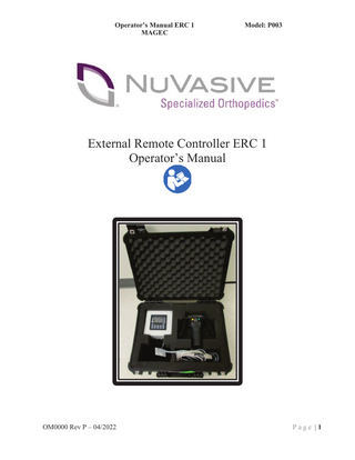
Operator’s Manual ERC 1 MAGEC
Model: P003
External Remote Controller ERC 1 Operator’s Manual
OM0000 Rev P – 04/2022
Page |1
Operator’s Manual ERC 1 MAGEC
Model: P003
Table of Contents 1.
SYMBOLS DEFINITION ... 3
2.
PRODUCT WARNINGS AND CAUTIONS ... 4
3.
PRODUCT DESCRIPTION ... 7
4.
COMPONENT IDENTIFICATION ... 8
5.
CONTRAINDICATIONS ... 9
6.
INSTRUCTIONS FOR USE... 9
7.
CONTROLS LAYOUT ... 11
8.
SCREEN NAVIGATION ... 13
9.
ALARM MESSAGES ... 16
10. MAINTENANCE & CLEANING ... 18 11. DISPOSAL ... 18 12. SPECIFICATIONS ... 19
OM0000 Rev P – 04/2022
Page |2
Operator’s Manual ERC 1 MAGEC
Model: P003
1. Symbols Definition For Symbols Glossary, please refer to https://www.nuvasive.com/eifu/symbols-glossary For Symbols specific to the ERC 1 reference the table below. Symbol IPX0
Definition The device offers no special protection from fluid ingress. Magnetic Hand Piece Alignment Align the Magnetic Hand Piece with this arrow pointing towards the patient’s head.
Extend Implant This symbol is located next to the Extend button on the Magnetic Hand Piece.
Retract Implant This symbol is located next to the Retract button on the Magnetic Hand Piece.
OM0000 Rev P – 04/2022
Page |3
Operator’s Manual ERC 1 MAGEC
Model: P003
2. Product Warnings and Cautions Please observe all safety precautions. 1.
* WARNING * Always confirm the predicted implant adjustment length displayed by the ERC with Xray measurements.
2.
* WARNING * Proper training of the External Remote Controller is required prior to operating this device. Only use the External Remote Controller in a manner consistent with this Operator’s Manual. Any alternative use may result in injury or damage to property.
3.
* WARNING * This equipment is intended for use by healthcare professionals only. This equipment may cause radio interference or may disrupt the operation of nearby equipment. It may be necessary to take mitigation measures, such as re-orienting or relocating the External Remote Controller or shielding the location.
4.
* WARNING* This device has not been tested for compatibility in Magnetic Resonance Imaging (MRI) environments and should not enter an MRI unit.
5.
* WARNING * Persons with a pacemaker or a similar medical aid should not handle or be exposed to the External Remote Controller. The strong magnetic fields may affect the operation of such devices.
6.
* CAUTION* The Rare-Earth Magnetics Association is not aware of any positive or negative health effects from handling rare-earth magnets. However, it is recommended that pregnant women not handle very strong rare-earth magnets (ERC).
7.
* WARNING * The External Remote Controller uses strong permanent magnets. Misuse of this system can cause serious personal injury. Always maintain a firm grip on the External Remote Controller and be very aware of other objects in your work area. The External Remote Controller may be pulled away from your hands or items may be pulled toward it if brought too close to other magnetic objects. Make sure there is at least 2 Feet (60 centimeters) around the work area that is free of metal objects such as instruments and tools before use. This includes personal items such as jewelry, watches, keys, and cellular phones. Do not use the ERC with metal/magnetic objects within the designated vicinity.
OM0000 Rev P – 04/2022
Page |4
Operator’s Manual ERC 1 MAGEC
Model: P003
8.
* WARNING * If this equipment is damaged, beware that magnet shards from broken magnets are very sharp. Always handle broken magnets with thick protective gloves. Contact NuVasive Specialized Orthopedics if the ERC is damaged.
9.
* WARNING * Never place the External Remote Controller near electronic media or appliances. The strong magnetic field may damage magnetic media such as floppy disks, credit cards, magnetic I.D. cards, cassette tapes, video tapes or other such devices. It can also damage televisions, VCRs, computer monitors and other CRT displays.
10. *WARNING* Never operate in ERC in an oxygen enriched or flammable environment.
11. * WARNING * There are no user serviceable components inside this device. Do not open the unit. Severe personal injury or damage to the equipment may result. Service should only be performed by qualified personnel.
12. * WARNING * Only use the supplied power cord for the ERC or an equivalent hospital grade cord rated for 10 Amps minimum. Contact NuVasive Specialized Orthopedics for a replacement charging cord.
13. * WARNING * Do NOT use this equipment in the presence of flammable anesthetics.
14. * WARNING * The ERC should only be placed immediately over the area of the patient’s body at the magnetic portion of the implant. Do not place the ERC near any other parts of the body, for example, portions of the body which may contain ferromagnetic material containing implants. When the ERC is not being actively used on the patient, it should always be kept within its protective case.
15. * WARNING * If, during implant adjustment, the ERC magnets fails to stop rotating, move the ERC at least 12 inches (30 centimeters) from the skin. This will undo the magnetic coupling between the ERC and the implant and will stop the adjustment. Place the ERC in its protective case and power off the unit. Unplug the device from the charging cord if the ERC is plugged in.
OM0000 Rev P – 04/2022
Page |5
Operator’s Manual ERC 1 MAGEC
Model: P003
16. * WARNING * If the ERC loses power during implant adjustment, contact NuVasive Specialized Orthopedics before continuing the implant adjustment.
17. * WARNING * Do not operate the ERC if it is dropped from a height of 3 feet or greater. If there is physical damage to the unit (e.g. unexpected noise, cracks) do not operate. If this does occur, please call the manufacturer NuVasive Specialized Orthopedics, Inc. and a replacement unit will be provided.
18. *WARNING* Do not lift the ERC unit using the adapter cord. Please return with the ERC.
19. * WARNING * Only operate the External Remote Controller by holding onto both of the handles provided.
20. * WARNING * If retraction of the NuVasive Specialized Orthopedics, Inc. Adjustable Implant is needed, never retract the implant more than the amount lengthened the previous week. Failure to follow this warning may result in pulling biological material that may have adhered to the rod of the implant into the internal space of the actuator of the implant.
OM0000 Rev P – 04/2022
Page |6
Operator’s Manual ERC 1 MAGEC
Model: P003
3. Product Description The NuVasive Specialized Orthopedics, Inc. (NSO) External Remote Controller, model P003, is a portable hand held device used to non-invasively extend or retract the MAGEC System. The Indications for Use of the ERC 1 when used with the MAGEC System is indicated for skeletally immature patients less than 10 years of age with severe progressive spinal deformities (e.g. Cobb angle of 30 degrees or more; thoracic spine height less than 22 cm) associated with or at risk of Thoracic Insufficiency Syndrome. TIS is defined as the inability of the thorax to support normal respiration or lung growth. For information related to the MAGEC System used with the ERC 1, refer to the respective implant system Instructions for Use (IFU) and associated labeling documents. The instructions for use are available online at www.nuvasive.com/eifu as identified by the symbol below on the product label.
OM0000 Rev P – 04/2022
Page |7
Operator’s Manual ERC 1 MAGEC
Model: P003
4. Component Identification Figure 1 identifies the major components of the system.
Controller
Hand Piece
Power Supply
Power Cord
Case
Figure 1: ERC 1 Components in the Case
OM0000 Rev P – 04/2022
Page |8
Operator’s Manual ERC 1 MAGEC
Model: P003
5. Contraindications Contraindications for the Magec System: x Patients with infections or pathologic conditions of bone which would impair the ability to securely fix the device (e.g. osteoporosis, osteopenia). x Patients with metal allergies and sensitivities to the implant materials (e.g. Titanium). x Patients with a pacemaker or other active, electronic devices (e.g. ICD). x Patients younger than two years old. x Patients weighing less than 25 lb. (11.4 kg). x Patients and/or families unwilling or incapable of following postoperative care instructions. x Patients with stainless steel wires or other implants containing incompatible materials. x Patients who are pregnant
6. Instructions for Use The following section describes the setup and procedure for implant adjustment using the External Remote Controller. 1) Have the patient remove any thick clothing like sweaters or jackets that may be covering the implant area. A thin, non-metallic, shirt is fine. 2) Have the patient remove any metal objects from their person (i.e. belts, buckles, jewelry, cell phones, keys, etc.) 3) Lay the patient face down on a non-magnetic examination table. 4) Cover the implant magnet area with a sterile drape. 5) Plug the External Remote Controller into an appropriate power outlet close to the patient. 6) Enter the absolute distraction length (Abs Length) of the patient’s implant into the control panel. 7) Select the desired adjustment mode (Incremental or Continuous). 8) Position the implant locating window of the Magnetic Hand Piece over the implant magnet area. The Magnetic Hand Piece should be oriented along the axis of the implant with its arrow pointing towards the patient’s head.
OM0000 Rev P – 04/2022
Page |9
Operator’s Manual ERC 1 MAGEC
Model: P003
implant locating window
Figure 2: ERC Placement Over Implant 9) Maintain the Magnetic Hand Piece orientation per Figure 2 while slowly sweeping it side to side and head to toe over the implant area. The Magnetic Hand Piece will pull downward towards the implant when it is in the optimal position. 10) Hold the Magnetic Hand Piece against the patient over the implant. 11) Press the Extend or Retract button as needed to adjust the implant as directed by the physician. 12) After adjustment, always confirm the amount of distraction by x-ray imaging. Reference Figure 3.
Standard Rod
Implant Magnet
Implant Magnet
7.
Offset Rod
Distraction Length
9.0 mm Reference Diameter
Figure 3: Implant Distraction Measurement from X-ray
OM0000 Rev P – 04/2022
P a g e | 10
Operator’s Manual ERC 1 MAGEC
Model: P003
Controls Layout Magnetic Hand Piece: The Magnetic Hand Piece has two handles for positioning the unit over the implant. The Magnetic Hand Piece also has two momentary push buttons. One push button for extending and the other for retracting the implant. Pressing and holding a push button causes the ERC to run in the desired direction. Releasing the button causes the ERC to stop. Pressing both buttons simultaneously also causes the ERC to stop. Reference Figure 4.
1 4
3
Implant Locating Window
2
Figure 4: Magnetic Hand Piece 1 2 3 4
Left handle. Right handle. Extend push button. Retract push button.
OM0000 Rev P – 04/2022
P a g e | 11
Operator’s Manual ERC 1 MAGEC
Model: P003
Control Panel: Figure 5 shows the layout of the control panel.
1
2
3
5
4
7 8
6
9
Figure 5: Control Panel Description: 1 2 3 4 5 6 7 8 9
Backlit LCD display. Upper Left Soft Key – The function of this key varies by screen. Upper Right Soft Key – The function of this key varies by screen. Lower Left Soft Key – The function of this key varies by screen. Lower Right Soft Key – The function of this key varies by screen. The ESC (escape) key cancels the current operation. The four arrow keys are used to move the cursor around the screen. The ENTER key is used to edit / enter data. The Function keys (F1-F10) are used to navigate between display screens and for data entry.
OM0000 Rev P – 04/2022
P a g e | 12
Operator’s Manual ERC 1 MAGEC
Model: P003
8. Screen Navigation The ERC has several screens used for various functions. The function and use of each screen is described in detail in this section.
a. Information Screen (F5) Press the F5 key to access the Information Screen shown in Figure 6. This screen displays specific information about the External Remote Controller. It displays the software version. It also displays an odometer reading that keeps tract of the total number of millimeters of use.
Figure 6: Information Screen
OM0000 Rev P – 04/2022
P a g e | 13
Operator’s Manual ERC 1 MAGEC
Model: P003
b. Main Operating Screen (F6) Press the F6 key to access the Main Operating screen shown in Figure 7. This screen displays information concerning the adjustment of the implant.
1
MODE
RESET 2
3
Figure 7: Main Operating Screen 11
The top line displays the current status of the system. The following messages are displayed. “Nuvasive Specialized Orthopedics, Inc.” The ERC is idle. “Increasing” The implant is increasing in length. “Decreasing” The implant is decreasing in length. “At Minimum Limit” The absolute length of the implant has reached its lower limit. “At Maximum Limit” The absolute length of the implant has reached its upper limit.
22
The second line displays the current ERC mode. The ERC can be placed into one of two different operating modes: Continuous Mode or Incremental Mode. To toggle between the two modes press the upper right (MODE) soft key. Continuous Mode: “Cont. Mode” Continuous mode allows the ERC to run as long as the Extend or Retract Hand Piece push buttons are held. The value displayed next to Cont. Mode increases or decreases as the implant is adjusted. To reset the value to zero, simply press the upper left (RESET) soft key. To enter a specific starting value, use the arrow keys to position the dashed box cursor over the value. Press the
OM0000 Rev P – 04/2022
P a g e | 14
Operator’s Manual ERC 1 MAGEC
Model: P003
ENTER key to select. The displayed value will change to a dark background when selected. Use the F1 – F10 keys to input the desired value. Press the ENTER key again to accept the new value or press the ESC key to abort the new entry. Values from 25.0 to -25.0 mm may be entered. Incremental Mode: “Inc. Mode” Incremental mode allows the user to input a fixed set point distance to move the implant. If a positive increment value is set, the ERC will automatically stop when the implant has extended to the set point value. If a negative increment value is set, the ERC will automatically stop when the implant has retracted to the set point value. To edit the increment set point value, use the arrow keys to position the dashed box cursor over the value. Press the ENTER key to select. The displayed value will change to a dark background when selected. Use the F1 – F10 keys to input the desired value. Use the Up Arrow key to change the sign (+/-) if needed. Press the ENTER key again to accept the new value or press the ESC key to abort the new entry. Incremental values from 25.0 to -25.0 mm may be entered. For positive increment values, press and hold the Extend Hand Piece push button. The ERC will extend the implant until the set point value is reached and then it will stop automatically. Note that releasing the Extend button always stops the adjustment. The set point value displayed will approach zero. Press the RESET button to reset the displayed value back to the set point. Note that the ERC will not extend until the set point is reset. However, the ERC will retract without limit as long as the retract button is pressed. For negative increment values, press and hold the Retract Hand Piece push button. The ERC will retract the implant until the set point value is reached and then it will stop automatically. Note that releasing the Retract button always stops the adjustment. The set point value displayed will approach zero. Press the RESET button to reset the displayed value back to the set point. Note that the ERC will not retract until the set point is reset. However, the ERC will extend without limit as long as the extend button is pressed. The bar graph below the increment value displays the percentage of the increment achieved. An all white bar indicates 0% increment and an all black bar indicates 100% increment. 33
The third line displays the Absolute Implant Distraction Length, “Abs. Length:”. This value increases and decreases with the implant as the ERC adjusts it. The bar graph below the absolute length indicates the percentage extended. An all white bar indicates 0% extension and an all black bar indicates 100% extension. To edit the absolute length value, use the arrow keys to position the dashed box cursor over the value. Press the ENTER key to select. The displayed value will change to a dark background when selected. Use the F1 – F10 keys to input the desired value. Press the ENTER key again to accept the new value or press the ESC key to abort the new entry. Absolute lengths from 0.0 to 48.0 mm may be entered.
OM0000 Rev P – 04/2022
P a g e | 15
Operator’s Manual ERC 1 MAGEC
Model: P003
9. Alarm Messages Several alarm messages may occur if the unit malfunctions. The alarm messages are described in the following section. ERC 1 Alarm Codes: The Alarm Screen appears if there is a malfunction with the ERC 1. A numeric value will appear beside the item labeled “ALARM.” The user will need to make note of the numeric alarm code number when contacting appropriate representative for technical assistance. Press the lower right soft button [Exit] to clear the alarm and return to the previous screen. Do not attempt to use a malfunctioning unit. When necessary contact your appropriate representative and let them know the Alarm Code Number. They will give you further instructions and send you a replacement ERC 1 if necessary. POSSIBLE ERROR CODE
DESCRIPTION
Alarm 00
Input Fault, I3
Alarm 01
Input Fault, I4
Alarm 02 Motor Direction Fault Not Extending
Alarm 03 Motor Direction Fault Not Retracting
Alarm 04 Motor Runaway! Extending
OM0000 Rev P – 04/2022
REASON and WHAT TO DO One of the motor monitoring leads is not functioning properly. Return the unit for service. Press the Alarm Reset button (lower right soft button) to return to the previous screen. One of the motor monitoring leads is not functioning properly. Return the unit for service. Press the Alarm Reset button (lower right soft button) to return to the previous screen. The unit is not extending the implant as requested. It is turning the wrong direction and retracting the implant. Return the unit for service. Press the Alarm Reset button (lower right soft button) to return to the previous screen. The unit is not retracting the implant as requested. It is turning the wrong direction and extending the implant. Return the unit for service. Press the Alarm Reset button (lower right soft button) to return to the previous screen. The motor is running without operator input. Remove the Hand Piece from the patient, place it in its protective case, and unplug it from the power source. Return the unit for service. P a g e | 16
Operator’s Manual ERC 1 MAGEC
Model: P003
Alarm 05
Motor Runaway! Retracting
The motor is running without operator input. Remove the Hand Piece from the patient, place it in its protective case, and unplug it from the power source. Return the unit for service.
Alarm 06
Motor Ground Fault
Alarm 07
Motor Encoder Fault
The motor common (-) potential is lost. Return the unit for service. Press the Alarm Reset button (lower right soft button) to return to the previous screen. The motor encoder is not pulsing properly. Return the unit for service. Press the Alarm Reset button (lower right soft button) to return to the previous screen.
OM0000 Rev P – 04/2022
P a g e | 17
Operator’s Manual ERC 1 MAGEC
Model: P003
10. Maintenance & Cleaning To clean the external surfaces of the ERC 1, wipe with 70% Isopropyl Alcohol Wipes or equivalent. Be sure that all parts are dry before putting the ERC back in the case. Do not submerge any component of the ERC in liquid. Severe personal injury or permanent damage to the ERC may result.
11. Disposal Do not dispose of the External Remote Controller in the trash. Please return it in its protective case to NuVasive Specialized Orthopedics, Inc. or call for disposal directions by calling customer service at 1-855-435-5477. Do not incinerate this equipment. The External Remote Controller contains rare earth magnets which burn extremely hot if ignited.
OM0000 Rev P – 04/2022
P a g e | 18
Operator’s Manual ERC 1 MAGEC
Model: P003
12. Specifications Description Display Accuracy Operating Temperature Operating Relative Humidity Storage Temperature Storage Relative Humidity Input Power Voltage (Single Phase) Input Power Frequency Input Power Current (Maximum) Weight: Magnetic Hand Piece Only External Remote Controller Device with Carrying Case Maximum Continuous On Time On Time / Off Time
Description Classification for Shock Protection Applied Part Type Shock & Leakage Current Defibrillation Rating Anesthetic Use Ingress Protection Method of Sterilization Pollution Degree Over Voltage Category
OM0000 Rev P – 04/2022
Rating ±10% + ±0.3 10 – 40 (50 – 104) 30 - 75 -10 – 60 (14 – 140) 5 – 95 (Non Condensing) 100 – 240 50 / 60 2.3 3.3 (7.3) 5.1 (11.2) 10.1 (22.3) 30 10 / 90
Units mm o C (oF) % o C (oF) % VAC Hz A kg (lbs) kg (lbs) kg (lbs) Minutes %
Rating Class II No reliance on protective earth, double insulated Type BF (Basic Floating) Not Defibrillator Proof Do NOT use this equipment in the presents of flammable anesthetics. (Neither AP nor APG) IPXO No protection from fluid ingress Non-Sterile Pollution Degree 2 (Office Environment) Category II
P a g e | 19
Operator’s Manual ERC 1 MAGEC
Model: P003
Guidance and manufacturer’s declaration – electromagnetic emissions The ERC is intended for use in the electromagnetic environment specified below. The customer or the user of the ERC should assure that it is used in such an environment. Emission test RF emissions CISPR 11 RF emissions CISPR 11 Harmonic emissions IEC 61000-3-2 Voltage fluctuations/ flicker emissions IEC 61000-3-3
Compliance Class B
Class B Complies
Electromagnetic environment - guidance The ERC may emit unintentional electromagnetic energy during normal operation up to permissible limits suitable for in establishments directly connected to a low voltage power supply network. The ERC is suitable for use in a clinical environment and those directly connected to the public low-voltage power supply network that supplies buildings used for domestic purposes.
Complies
Guidance and manufacturer’s declaration – electromagnetic immunity The ERC is intended for use in the electromagnetic environment specified below. The customer or the user of the External Remote Controller should assure that it is used in such an environment. Immunity test IEC 60601 Compliance Electromagnetic environment – test level level guidance Electrostatic ± 2, 4, 6 kV (contact) Complies Floors should be wood, concrete, or discharge (ESD) ceramic tile. If floors are covered with IEC 61000-4-2 ± 2, 4, 8 kV (air) synthetic material, the relative humidity should be at least 30 %. ± 2, 4, 6 kV (indirect) Electrical fast ± 2 kV for power supply Complies Mains power quality should be that of a transient/burst lines typical commercial or hospital ± 1 kV for input/output IEC 61000-4-4 environment. lines Surge ± 0.5, ± 1.0 kV (differential Complies Mains power quality should be that of a IEC 61000-4-5 mode) typical commercial or hospital ± 2 kV (common mode) environment. Voltage dips, short <5 % UT (>95 % dip in UT) Complies Mains power quality should be that of a interruptions and for 0.5 cycle typical commercial or hospital voltage variations on environment. If the user of the External power supply input 40 % UT (60 % dip in UT) Remote Controller requires continued for 5 cycles lines operation during power mains IEC 61000-4-11 interruptions, it is recommended that the 70 % UT (30 % dip in UT) External Remote Controller be powered for 25 cycles from an uninterruptible power supply or a battery. <5 % UT (>95 % dip in UT) for 5 s Power frequency 3 A/m Complies Power frequency magnetic fields should (50/60 Hz) magnetic be at levels characteristic of a typical field location in a typical commercial or IEC 61000-4-8 hospital environment. NOTE UT is the a.c. mains voltage prior to application of the test level.
OM0000 Rev P – 04/2022
P a g e | 20