Technical Reference Manual
56 Pages
Preview
Page 1
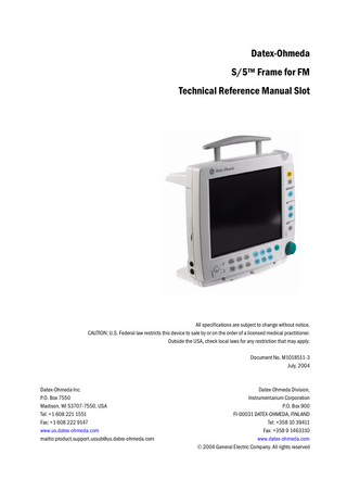
Datex-Ohmeda S/5™ Frame for FM Technical Reference Manual Slot
All specifications are subject to change without notice. CAUTION: U.S. Federal law restricts this device to sale by or on the order of a licensed medical practitioner. Outside the USA, check local laws for any restriction that may apply. Document No. M1018511-3 July, 2004
Datex-Ohmeda Inc. P.O. Box 7550 Madison, WI 53707-7550, USA Tel: +1 608 221 1551 Fax: +1 608 222 9147 www.us.datex-ohmeda.com mailto:[email protected]
Datex-Ohmeda Division, Instrumentarium Corporation P.O. Box 900 FI-00031 DATEX-OHMEDA, FINLAND Tel: +358 10 39411 Fax: +358 9 1463310 www.datex-ohmeda.com 2004 General Electric Company. All rights reserved
Table of contents
Table of contents Introduction 1
Specifications 1.1 1.2 1.3 1.4 1.5 1.6 1.7 1.8
2
2.2
3.3
5
Introduction... 5 2.1.1 Keyboards... 5 2.1.2 Display... 5 2.1.3 CPU board... 6 2.1.4 DC/DC board... 7 2.1.5 AC/DC unit... 9 2.1.6 Module bus flex board...10 2.1.7 Interconnection board...10 2.1.8 Sync connector board...11 2.1.9 Display connection board...11 2.1.10 Wireless LAN option, F-FMW...11 2.1.11 Batteries...12 Connectors and signals...13 2.2.1 External connectors...13 2.2.2 Digital and analog outputs... 17 2.2.3 Printer connection...18
Service procedures 3.1 3.2
2
Frame for FM... 2 1.1.1 Electrical requirements... 2 1.1.2 Environmental requirements... 2 LCD display... 2 Batteries... 3 MemCards... 3 Network... 3 Wireless Network, F-FMW... 4 Analog Outputs, direct ECG and synchronization... 4 Digital outputs... 4
Functional description 2.1
3
1
19
General service information...19 Service check...19 3.2.1 S/5TM FM...19 3.2.2 Recommended tools...20 3.2.3 Recommended parts...20 3.2.4 Before beginning...20 3.2.5 General...20 3.2.6 Recorder Unit...25 3.2.7 MemCard option...26 3.2.8 Network option...27 3.2.9 Wireless LAN option...29 3.2.10 General...29 S/5 FM disassembly and reassembly...30
i Document No. M1018511-3
Datex-Ohmeda S/5™ FM
3.4
3.5 3.6 3.7
4
3.3.1 Before disassembly...30 3.3.2 Handling and storage of LCD display component...37 Batteries...44 3.4.1 Battery indicators...44 3.4.2 To change the batteries...45 3.4.3 To check the battery...45 3.4.4 Conditioning the batteries...46 To replace the fuses...46 3.5.1 Primary fuses...46 3.5.2 Fuse for external DC...46 To download the software on CPU board...46 Adjustments and calibrations... 47
Troubleshooting 4.1 4.2 4.3
48
S/5 Frame for FM...48 Memory option...50 NET section...50
ii Document No. M1018511-3
S/5™ Frame for FM, F-FM
Introduction This section provides information about the maintenance and service of the following products:
• • •
S/5™ Frame for FM, F-FM. Software Licenses L-FICU03, L-FICU03A. WLAN option F-FMW.
Figure 1
S/5™ Frame for FM
1 Document No. M1018511-3
Datex-Ohmeda S/5™ FM
1
Specifications
1.1
Frame for FM Dimensions Height
302 mm (11.8 in) 274 mm (10.7 in)
Width
302 mm (11.8 in) Without modules 337 mm (13.3 in) With modules
Depth
143 mm (5.6 in) 156 mm (6.1 in) 200 mm (7.8 in)
Weight FM FM + E-PSM FM + N-FCREC + E-PSM
1.1.1
Handle Up Handle Down
4.8 kg 5.4 kg 6.4 kg
Without extension module With extension module With extension and PSM modules
FM without modules, batteries included FM with PSM FM with PSM and extension module with recorder and CO2
Electrical requirements Mains input Voltage 100 to 240 Vac ± 10% Current 1.25A @ 100V, 625mA @ 240V Frequencies 50/60Hz Power Consumption 150 VA Ext. DC Input Voltage Current Cooling
1.1.2
Environmental requirements Operating temperature normal operation with CO2 measurement while charging batteries Storage temperature Relative humidity Atmospheric pressure
1.2
10 - 16V 6 A max Convection
0 to 40°C 50 - 95 °F 10 to 40°C 14 - 122 °F 0 to 35°C 50 - 95 °F -20 to +60°C 10 … 90%. Non-condensing 670 to 1060 mbar (500 to 800 mmHg, 670 to 1060hPa)
LCD display Display size Display type
2 Document No. M1018511-3
10.4 in (diagonal) Active Matrix Color TFT LCD
S/5™ Frame for FM, F-FM
Resolution Number of waveforms Number of digit fields Display layout and colors Horizontal viewing angles Vertical viewing angles
SVGA 800x600 Up to 6 (8) Up to 4 User-configurable Left and right side 50° Lower side 45° Upper side 35° Backlight 2 x CCFT(E) Backlight lifetime 40 000h Backlight intensity 280 Cd/m2 typ. Integrated Command Board with direct function keys, menu keys and ComWheel for selections and adjustments in menus.
1.3
Batteries Number of Batteries Battery type Voltage Capacity Capacity Indicator Run time Charge time Battery life Conditioning
1.4
MemCards MemCard capacity Data storage capacity Operating system File system MemCards
1.5
2 Exchangeable Lithium-Ion 11.1V (nominal) 3,8 Ah Fuel gauge on monitor screen and on battery pack 5 hours (2:30 hours per battery pack) 2 hours per battery pack 300 cycles to 50% capacity Manual
6 MB minimum 2 days of continuous physiological data trends Datalight ROM-DOS MS-DOS compatible PCMCIA-ATA compatible memory cards
Network Connector type RJ-45 Network type 10 Base-T Isolation 1500 V, 60/50Hz, 1 min. Network ID Network ID key and virtual network ID Communication protocol DRI 01, 02 and 03 Network Connectivity D-O Central and iCentral Meets IEEE802.3 specifications (10MBASE-T) Hospital grade approved data transformer Coding element interface
3 Document No. M1018511-3
Datex-Ohmeda S/5™ FM
1.6
Wireless Network, F-FMW Type Frequency range Data rate Output power Data transmission Security Certificates
1.7
Analog Outputs, direct ECG and synchronization ECG InvBP
Pacer
1.8
Built-in transceiver and antenna Worldwide product covering 2.4 to 2.5 GHz, programmable for different country regulations 11 Mbps per channel (max.) 100 mW IEEE 802.11b compliant, Direct Sequence Spread Spectrum (DSSS) Wired Equivalent Privacy (WEP) 40 and 128 bit encryption Wi-Fi-certified
Direct ECG delay 15 ms (max.) Gain ECG (in)/ECG(out) 1 mV/1V InvBP Output ‘Art’ from E-PSMP InvBP Delay 25ms (max.) Gain InvBP 1V/100mmHg (0...300mmHg) 5 V and 2 ms pulse
Digital outputs Nurse call Defibrillation Synchronization
Serial Output
4 Document No. M1018511-3
Low State: 0-0.8V; High State: 2.8-5V Generated on red, yellow and white alarms State 0: 0-0.8V; state 1: 2.8-5V Delay (max): < 35 ms from R peak 5 V and 10 ms pulse Asynchronous Serial data interface, uses RS-232 standard Baud rate max 115.2 kbps Parity: None; Data bits: 8; Stop bit: 1
S/5™ Frame for FM, F-FM
2
Functional description
2.1
Introduction
EXT DC Connectors AC/DC unit SW PCMCIA WLAN CPU board
B a t t 1
DC/DC board
B a t t 2
N-FC(REC) Display unit E-PSM(P)
Figure 2
2.1.1
S/5 FM frame block diagram
Keyboards Vertical and Horizontal Membrane keypad containing 17 direct function keys. The keypads are foil membrane keypads. There is no separate processor for the keypads. The keypads are connected to the UPI section of the CPU board.
2.1.2
Display The 10.4” LCD display with SVGA 800 x 600 resolution has bright long live lamps and a wide viewing angle. NOTE: The LCD display backlight circuit runs on a high voltage. Do not touch the inverter board or the backlight tube leads when powered.
5 Document No. M1018511-3
Datex-Ohmeda S/5™ FM
Backlights The backlight consists of two replaceable cold-cathode fluorescent tubes driven by a separate inverter board.
2.1.3
CPU board
Figure 3
CPU board
The board is based on Intel/AMD 486DX4 microprocessor and Radisys R400EX chip set. Other features include flat panel display controller, 10 Mbit/s Ethernet interface, PCMCIA interface, sound system and Hitachi H8S based UPI. The CPU section takes care of the central processing. The main features are:
• • • • • •
486 processor Internal clock frequency 75MHz 32 Mbytes DRAM 8 Mbytes program flash memory 32 Kbytes static RAM with real time clock 4 channel UART: − −
• •
2 serial channels with signals in AC-logic level 2 serial channel signals in RS232-level
Programmable alarm sound generator PC-card slot for software updates
The SRAM with real-time clock is backed up by a lithium battery.
CAUTION
The SRAM/Timekeeper IC contains a lithium battery. Discard the battery according to local regulations.
6 Document No. M1018511-3
S/5™ Frame for FM, F-FM
Connectors Power supply board connector X3 Flat panel connector X7 Speaker connector X17 Analog output board connector X4 Ethernet connector X20
System watchdog and voltage supervision There are two voltage supervision chips that control the system reset signals. The +3.3V supervision chip outputs reset signals for +3.3V devices. Reset is activated when voltage is below 3.08V. It also has a watchdog that is refreshed in normal operation and in standby. The +5V supervision chip outputs reset signals for +5V devices. Reset is activated when voltage is below 4.63V. +5V reset causes also +3.3V reset through a FET.
2.1.4
DC/DC board The DC/DC board converts the output voltage of AC/DC unit, external DC unit or battery voltage to various supply voltages for the electronics of FM monitor. The DC/DC board takes care of the battery charging.
Figure 4
DC/DC Board
DC/DC board functional blocks DC/DC board operation is controlled by the PMC (Power Management Controller) CPU. PMC takes care of power path controlling and power supplies' sequencing. It communicates with the main CPU via serial communication. PMC also measures DC/DC board voltages and currents. High efficiency switching power supplies and power path switches are used on the DC/DC board. This is because of no-fan requirement for PM monitor as well as maximizing the battery time. Circuit breakers make VSYS and MOD voltages short-circuit protected. Also the battery charger, +5V and +3.3V switchers withstand short-circuit. +5V_OUT is disconnected from +5V by a circuit breaker in case of +5V_OUT overload. The boost converter can be set to two different output levels. The higher one is used to give the battery charger adequate input voltage when the DC/DC board input comes from external DC source. The lower one is set in ACDC use to keep the boost converter enabled but passed by a diode and thus not 7 Document No. M1018511-3
Datex-Ohmeda S/5™ FM
switching, which minimizes the power loss. When the ACDC voltage drops the boost converter starts regulating its output and keeps the MOD voltages at a level a little lower than the one in ACDC use. In battery use the lower output voltage yields a little better efficiency, too. Smart batteries, battery charger and PMC communicate via SMBus (System Management Bus). It is a two-wire interface closely resembling I2C. Smart battery controls the charging and calculates and stores the capacity information as well as other battery related data. Batteries can be charged when external DC or ACDC voltage is present. Block diagram of the power supplies is represented in Figure 5
DC/DC BOARD FUNCTIONAL BLOCKS
AC / DC 15.9V +/-2%
2x BATTERY 10.8V Li-ION (9-12.6V)
EXTERNAL DC 10 - 16.5V
SMART BATTERIES = DC/DC-BOARD POWER PATH SWITCH
POWER PATH SWITCH SMART BATTERY CHARGER (BUCK)
VSYS 9 - 16.2V
14.6V / 15.4V SET_HI 2-LEVEL BOOST
Boost converter 15.4V (set_hi) 14.6V passed by diode
Power source @ EXTDC @ Battery @ AC/DC dcdc_brd_block.vsd
CIRCUIT BREAKER
VBOOST 14.1 - 16V
5V_PMC 3.3V BUCK
5V BUCK
PMC CPU & ON/STBY LOGIC
SERIAL COMM. & ON/STBY CTRL
Figure 5
8 Document No. M1018511-3
CIRCUIT BREAKER
CIRCUIT BREAKER
+3.3V
+5V
+5V_OUT
DC/DC board block diagram
VSYS_OUT 9 -16.2V
I/O_VMOD 13.8- 16V
VMOD 13.8 -16V
S/5™ Frame for FM, F-FM
Battery charger Battery charger is a Level 2 Smart Battery Charger. It communicates with the batteries and PMC CPU via SMBus interface. The charger acts as a SMBus slave device that responds to charging current and charging voltage values sent to it by a Smart Battery. The charger includes input current limiting feature. In a case where the input current exceeds the limit the charger reduces the output current to keep the input within the limit. The currents of the MOD voltages (VMOD, I/O_VMOD) are taken through this current measurement as well. This results that the charger reduces its output current if the sum of the charger input current and MOD currents exceeds the input limit. The purpose of this is to prevent the input power sources from getting overloaded if MOD power is increased during charging.
Power path switching electronics The power source to be used (batteries, external DC or AC/DC output) is chosen initially by a ‘power path controller’ inside this block. The PMC CPU has full control over the power path management after the initial choice is made at startup.
2.1.5
AC/DC unit
Figure 6
AC/DC unit
AD/DC unit The AC/DC unit is a compact power supply based on new high-efficiency technology from Condor. It is designed for 65 watt continuous output with convection cooling, 15.9V requirements, and universal AC input. This AC/DC unit is especially well-suited to medical systems. The high-efficiency allows it to function in an enclosed case, with minimal heat dissipation.
9 Document No. M1018511-3
Datex-Ohmeda S/5™ FM
2.1.6
Module bus flex board
Figure 7
Module bus flex board
Module bus flex Interconnection board connector X1 Module bus connector X2 (pins 21...25) Sync connector board connector X3
2.1.7
Interconnection board
Figure 8
Interconnection board
Interconnection board takes care of most of the monitor internal cabling. CPU board connector X1 Module flex board connector X2 Defib&IABP sync connector X3 DIS connector X4 Fuse for External DC input
10 Document No. M1018511-3
S/5™ Frame for FM, F-FM
2.1.8
Sync connector board
Figure 9
Sync connector board
CPU board connector X1 Module bus flex board connector X2 DIS connector X4 Sync IABP& DEF connector X3
2.1.9
Display connection board
Figure 10
Display connection board
CPU board connector X1 Display connector X2
2.1.10 Wireless LAN option, F-FMW S/5 Wireless Network is an extension to, or an alternative for, a wired Datex-Ohmeda Monitor network. It provides same network services than the wired S/5 Network. The monitor network is a local area network based on standard Ethernet technology. The monitor network is formed by connecting one Central and up to 32 bedside monitors together.
11 Document No. M1018511-3
Datex-Ohmeda S/5™ FM
The Central and the bedside monitors are connected to a 10 Mbps hub. The hub works as a multiport repeater and controls the information flow between all the devices connected to the monitor network. The communication protocol for the monitor network is Datex-Ohmeda specific. Wireless bedside monitors can use both the wired and wireless network. If the network cable is connected, the wired S/5 Network is used. Network connection is changed automatically between LAN and WLAN. LAN overrides when available. For using Wireless LAN connection, the monitor frame with ready-fitted WLAN option F-FMW is required. For configured parameters please refer to the S/5 Network, Wireless LAN Installation Guide.
2.1.11 Batteries The S/5 FM has two lithium-ion batteries, located in the battery compartment. The DC/DC board connects one of the batteries to be the power source, if no power is received from the AC/DC unit or from an external DC unit. The battery charging is controlled by the DC/DC board. The batteries can be charged separately, and screen symbols and monitor frame LED indicators indicate their charging level and possible failure. NOTE: When the monitor is battery powered, the green battery LED is on. When the monitor is mains/ external DC powered, the green mains/external DC LED is on.
12 Document No. M1018511-3
S/5™ Frame for FM, F-FM
2.2
Connectors and signals
2.2.1
External connectors
X4
X3
X5
1
X6
2
X1
X7 Figure 11
X8
X9
X2
External connectors of Frame for FM
(1) Fuses (2) Potential equalization connector X1 NET connector X2 Multi IO connector X3 Receptacle for power cord X4 Module Connector for E-PSM, E-PSMP or N-FMC, N-FMCREC, N-FMREC X5 Defib & IABP sync connector X6 Connector for DIS interfacing system X7 Connector for Remote Controller K-CREMCO X8 NET ID connector X9 Serial connector
13 Document No. M1018511-3
Datex-Ohmeda S/5™ FM
Network connector, X1 RJ45 connector
1 2 3 4 5 6 7 8
Pin
Signal
1 2 3 4 5 6 7 8
Tx + Tx Rx + N/C N/C Rx N/C N/C
Pin
Signal
1 2 3 4 5 6 7 8 9 10 11 12 13 14 15 16 17 18 19 20 21 22 23 24 25
GND NET_ID_DO, TTL out. NET_ID_DI, TTL input NET_ID_CLK, TTL out NET_ID_CS, TTL out TXD, RS-232 output RXD, RS-232 input NURSE_CALL, CMOS output reserved Data -, RS-485 I/O CONNECTOR_ID, TTL input EXTDC+, 10-16V, input GND GND KB_DATA#, TTL, I/OPin KB_CLK#, TTL, I/O +5V_OUT, +5V, output CTS#, RS-232 input RTS#, RS-232 output REMOTE_ON# reserved Data +, RS-485 I/O I/O_VMOD, 13,8 - 16V EXTDC+, 10-16V, input GND
Multi I/O connector X2 25 pin male connector
13
1
25
14
14 Document No. M1018511-3
S/5™ Frame for FM, F-FM
Multi I/O adapter
Figure 12
Multi I/O adapter
Connector for K-CREMCO X 7 5 pin connector
Pin
Signal
1 2 3 4 5
KB_CLK KB_DATA not in use GND 5 +4,75 - +5,25V
Pin
Signal
1 2 3 4 5 6 7 8 9
NET_ID_CS, TTL out. NET_ID_CLK, TTL out. NET_ID_DO, TTL out. NET_ID_DI, TTL input GND +4.75 . . . +5.25V Not in use NURSE_CALL, CMOS output GND for Network ID
Net ID connector X8 9 pin female connector
1
5
6
9
Nurse Call (pin 8) The nurse call signal is generated by the red, yellow and white alarms. When activated, the signal is set to the high state and remains at the high state until the alarm situation is over or the SILENCE ALARM key is pressed. The high state range is from 2.8 to 5 V, while the low state range is from 0 to 0.8 V. If the output signals are used simultaneously with the coding element, the B-UPINET Y-cable, order number 889308, should be used.
15 Document No. M1018511-3
Datex-Ohmeda S/5™ FM
Serial port X9 9 pin male connector
Pin
1
5
6
9
1 2 3 4 5 6 7 8 9
Signal RXD, RS-232 input TXD, RS-232 output +4.75 . . . +5.25V GND RTS#, RS-232 output CTS#, RS-232 input
Main power X3 Mains connector
Pin
Signal
L PE N
Live Protected earth Neutral
Pin
Signal
1 2 3 4 5
GND Vmod 13.8 - 16 V Data + Data Shield
Module connector X4 5 pin female connector
16 Document No. M1018511-3
S/5™ Frame for FM, F-FM
Defib & IABP sync connector X5 mini din7 connector
Pin
Signal
1 2 3
Defib sync Marker_in Analog GND
5 6 7 8
Digital GND Reserved Pressure_out Direct_ECG
DIS connector, X6 DIS interface (RS485) 10 -pin female connector
2.2.2
Pin
Signal
1 2 3 4 5 6 7 8
Data + Data 13.8 -17 VMOD GND NIC GND NIC MNIC
Digital and analog outputs
Digital outputs There are separate digital outputs. Both signals use TTL-level. The outputs are: Defibrillation Sync. and Nurse Call. The Defibrillation Synchronization Signal is obtained from Synchronization connector X5, pin 1. The Nurse call is obtained from Net ID connector X9, pin 8. Defibrillation Sync indication is generated by ECG. When active, the signal is state 1. After 10 ms the signal is reset to state 0. New Defibrillation Sync is not generated before the indication is deactivated. The delay from the R wave peak to the start of the signal is maximally 35 ms. Nurse Call indication is generated by red, yellow and white alarms. When activated, it is set to state 1 and remains at that state until the alarm situation is over or SILENCE ALARM key is pressed. The range of state 0 is from 0 to 0.8 V, and range of the state 1 is 2.8 to 5 V.
Analog outputs S/5 FM produces two analog real-time signals. The Direct ECG signal is available in Defib&IABP sync connector X5 pin 8 and Net ID connector X8, pin 3. The other signal is Invasive pressure output. It is available in Synchronization connector X5 pin 7. NOTE: When source of the selected analog output becomes invalid (for example, transducer is disconnected), the last valid waveform information remains on the output and the numerical information is no longer valid. Direct ECG Delay (max.): 15 ms Gain ECG (out)/ECG (in): 1 V/1 mV Pacer: 5 V and 2 ms pulse
17 Document No. M1018511-3