Oxylitre Limited
Medical Regulators and Flowmeters
R1400&R2400 Series Medical Regulators Operating & Safety Instructions Issue No 5.6 Date Aug 2012
Operating & Safety Instructions
2 Pages
Preview
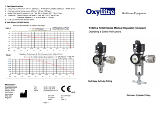
Page 1
7. Test Specifications Input pressure: Maximum 138 bar (2000 psi ) – R1400 Series; 200 Bar (2900 psi) – R2400 Series Flowmeter setting input pressure: Minimum 103 bar (1500 psi). Safety Valve blow off pressure: 5.5 to 7 bar (80 to 100 psi). MA-7 (10 to 11 bar). Tolerances: Output Pressure: 58 (4 bar) ± 5 psi; MA-7 101 (7 bar) ± 5 psi Flowmeter Readings: ± 10 % of full scale (> 1.5 LPM). e. Leak Test, Permissible leakage: None. a. b. c. d.
Healthcare Equipment
8. Line Charts (R1400 Series)
R1400 & R2400 Series Medical Regulator (Compact)
Table 1
Operating & Safety Instructions
Table 2
Bull Nose Cylinder Fitting Manufacture Oxylitre Limited Morton House Skerton Road Old Trafford Manchester M16 0WJ England
Tel: Fax: email:
(0)161 872 6322 (0)161 848 7914 [email protected] 0473 Doc Ref: Issue No: Date: Page 3
Doc-OP-4201 5.6 24.8.12
Pin-Index Cylinder Fitting
1. Introduction The Oxylitre R1400 & R2400 Series Regulator has been designed specifically for medical use and is available for use with Oxygen, Air and Entonox. Conforms to BS EN ISO 10524-1.
Flow is available only at the numbered increments. There is NO FLOW between increments (and at 0). The indicating pointer must point to a specific number on the dial and the number to be centrally located in the window to obtain flow.
2. Specifications Inlet Connection All gas connections comply with National and International Standards for safety and prevention of connecting an incorrect gas (BS 341-3 for Bull Nose; BS EN ISO 407 for Pin Index). Optional Outlet Connectors The R1400 & R2400 Series Regulators are available with or without a 0-15, 0-3 or 0-1 LPM Select-aFlow Flowmeter or Thorpe Tube type Flowmeter. Units are also available with a gas specific (Quick Release) Self Sealing Valve. Outlet Pressure The R1400 & R2400 Series Regulators are preset to 4 bar (400 kPa). Filters (Please Note: Filters should only be replaced by authorised/trained Personnel). Each Regulator is fitted with two integral filters that will protect the patient and/or the user from any foreign matter. The first Filter is placed in the inlet stem of the regulator. The second filter is place at the regulators’ output Self Sealing Valve/Flowmeter. Gauges Each Regulator is fitted with an easy to read, colour coded Contents Gauge. Safety Valve The Safety Valve System has been designed to release gas pressure for the safety of the user/patient and/or the equipment connected to the Regulator. This will operate only if the working pressure increases due to a malfunction in the regulator (the Safety Valve System is not an adjustable device).
3. Instructions for use Fitting to a Cylinder (Note: Take great care with these operations): Before connecting a Regulator to a Cylinder, momentarily open and close the Cylinder Valve to blow out any accumulated dust or moisture. Inspect the inlet connector seal for signs of damage or contamination, if found replace immediately! These seals should be replaced at least once a year i.e. as part of a Standard Service (Note: NEVER use two seals together). Seal for Pin Index Inlet Connectors = Part No: OX010 (BODOK) Seal for Bull Nose Inlet Connectors = Part No: BS110 (‘O’ Ring) Connect the Regulator securely to the Cylinder. Ensure the flowmeter or other attachment is fully closed off. Open the Valve very slowly (approximately one full turn) to reduce the danger of explosion or fire arising from pressure shock. Check the contents of the Cylinder, if or when the Gauge Indicator Needle points in the red section on the Gauge (below ¼ full), replace the Cylinder. Using the Select-a-Flow Flowmeter (if fitted) Before use, ensure that the correct sized Mask/Nasal Cannula and Connecting Tube is used. Oxylitre Recommendations: Mask: IS1106/1140; Connecting Tube: IS1174; Nasal Cannula IS1161. Connect the Delivery Tube to the Mask/Nasal Cannula and connect the other end of the tube to the Multi-sized Tubing Outlet on the Regulator. The Mask or Nasal Cannula can now be placed on the patient. Always check the contents of the Cylinder indicated by the Contents Gauge. From the “0” position, rotate the Select-A-Flow Flowmeter Control Knob clockwise until the required Litre flow for therapy administration has been selected with a noticeable ‘CLICK’. The Litre Flow is indicated in the window of the Flowmeter Control Knob. Page 1
When the user/patient has finished, rotate the Control Knob anti-clockwise to the “0” position. Removing the Regulator from the Cylinder: Turn OFF the Cylinder Valve. Bleed Off the remaining pressure retained in Regulator by opening a Valve connected to the Regulator (or if a Flow-metering Device is fitted, turn the Flow Control Knob to a Flow Selection). When the indicator on the Contents Gauge has fully dropped, disconnect from the Cylinder SLOWLY.
4. Safety Precautions for the prevention of Fire & Explosion The Regulator or patient MUST NOT be allowed near any source of ignition i.e.: Cigarette/cigar/pipe smokers, sparks, naked flame, open electrical appliances. This precaution applies during and after patient use. Warning: This Regulator MUST NOT come into contact with any Oil or Grease, a reaction may cause an Explosion/Fire.
5. Maintenance A Medical Regulator forms part of an essential support system. Regulators must be treated with care and maintained on a regular basis, to ensure the unit’s reliability and quality for the purpose that it is used for. The units require cleaning on external surfaces only by using a solution of luke-warm water and “Dettol” or similar disinfectant fluid (read disinfectant instructions) and cleaning cloth. Inspection Recommended at least annually by a Service Engineer and consist of: a. Check Seal as stated on section 3. b. Connect Regulator to the Cylinder as stated in section 3. c. Check the Contents of Cylinder that is indicated by the Pressure Gauge. d. Close the Cylinder Valve and observe the Contents Gauge for pressure drop. If Gauge Needle descends, this indicates a leakage in the system. The device will require service or repair. Service/Repair Servicing should be only carried out by fully qualified technicians. A Major Service is recommended every 5 years. For service enquiries and information, please contact our sales office. NEVER USE FAULTY EQUIPMENT. Preventative maintenance ensures safety for the patient and user.
6. Technical Data Specifications a. Maximum Inlet Pressure: R1400 Series 2000 psi (138 bar); R2400 Series 2900 psi (200 bar) b. Minimum Inlet Pressure: 400 psi (27.6 bar) c. Output Pressure: 58 psi (4 bar); Tolerance: 3.5 to 5 bar (100 psi (7 bar) MA-7) d. Flow Rates: See graph on the next page (R1400 Series) e. Standard Discharge: 90 LPM Please see Table 1 for the Regulators performance specifications. This indicates the performance of the device set at the standard output pressure and discharges at varied inlet pressures. Please see Table 2 for the Regulators’ Pressure characteristics when the Flowmeter is in operation. The chart indicates the variation of the output pressure during flow and when the Regulator output pressure has been set at the upper and lower input pressures. Flow calibration range a. 0 to 15 LPM ± 10% Full Scale b. 0 to 3 LPM ± 10% Full Scale (± 20% 0.25 to 1.5 LPM) c. 0 to 1.1 LPM ± 20% Full Scale Page 2