Portascan
CARESCAPE series Modules and Frames
CARESCAPE Monitor B850 Supplement to BP-CO-Temperature Module Service Manual Jan 2013
Supplement to Service Manual
6 Pages
Preview
Page 1
GE Healthcare
Instructions PN 2068969-002
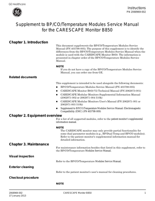
Supplement to BP/CO/Temperature Modules Service Manual for the CARESCAPE Monitor B850 Chapter 1. Introduction
This document supplements the BP/CO/Temperature Modules Service Manual (PN 403798-005). The purpose of this supplement is to identify the differences from the BP/CO/Temperature Modules Service Manual when the module is used with the CARESCAPE Monitor B850. The information is presented in chapter order of the BP/CO/Temperature Modules Service Manual. NOTE If you do not have a copy of the BP/CO/Temperature Modules Service Manual, you can order one from GE.
Related documents This supplement is intended to be used alongside the following documents:
BP/CO/Temperature Modules Service Manual (PN 403798-005)
CARESCAPE Monitor B850 V2 Technical Manual (PN 2062973-001)
CARESCAPE Modular Monitors Supplemental Information Manual (2062971-002 or 2062971-004 510k)
CARESCAPE Modular Monitors User's Manual (PN 2062971-001 or 2062971-003 510k)
Supplement to BP/CO/Temperature Modules Service Manual: Electromagnetic Compatibility (EMC) (PN 403798-009)
Chapter 2. Equipment overview
For a list of all supported modules, refer to the patient monitor’s supplemental information manual. NOTE The CARESCAPE monitor may only provide partial functionality for some dual parameter modules (e.g., BP/Dual Temp and BP/CO modules). Refer to the patient monitor’s supplemental information manual for detailed information.
Chapter 3. Maintenance
For maintenance information besides that listed in this supplement, refer to the BP/CO/Temperature Modules Service Manual.
Visual inspection Refer to the BP/CO/Temperature Modules Service Manual.
Exterior cleaning Refer to the patient monitor’s user’s manual for cleaning procedures.
Checkout procedure NOTE
2068969-002 17 January 2013
CARESCAPE Monitor B850
1
The CARESCAPE monitor may only provide partial functionality for some dual parameter modules (e.g., BP/Dual Temp and BP/CO modules). Refer to the patient monitor’s supplemental information manual for detailed information.
Blood pressure parameter/Invasive pressure test Required tools A multiparameter patient simulator with invasive pressure adapter cables to GE invasive pressure connectors
Single BP cable
Preparation 1. Install the module in a Tram-rac 4 housing. 2. Make sure the power indicator of the monitor is turned ON. 3. Install module under test. 4. Connect patient cable to module. 5. Attach appropriate leads to the simulator. Test procedure Refer to the Blood Pressure Parameter test in the BP/CO/Temperature Modules Service Manual.
Electrical safety tests Refer to the electrical safety tests found in the CARESCAPE Monitor B850 Technical Manual. This information supersedes the instructions found in the BP/CO/Temperature Modules Service Manual.
2
CARESCAPE Monitor B850
2068969-002
Check form 1. Complete one sheet per unit. 2. Prior to testing, verify all equipment is calibrated via calibration labeling, and record calibration due date. Test configuration, conditions and test equipment for unit under test Product/Model
Customer asset tag
Maintenance type: Planned maintenance
Serial number
Comments
Corrective maintenance Measuring equipment used
ID number
Manufacturer
Model number
Description
Results
Maintenance procedure
Pass
Visual inspection
Serial number
Checkout procedure
Fail
Cal due date
Results Pass
Fail
Blood pressure test
Exterior cleaning Electrical safety tests Refer to the CARESCAPE Monitor B850 Technical Manual
Test results: Pass Fail
2068969-002
Signature of tester:
CARESCAPE Monitor B850
Date:
3
Chapter 4. Troubleshooting
With the exception of the troubleshooting procedure below, refer to the BP/ CO/Temperature Modules Service Manual.
Troubleshooting procedure Is LED on front panel green?
Yes
No
Is patient data displayed at the monitor? Yes Yes
Chapter 6. Dual BP module
Try one of the following solutions: 1. Verify that the patient connections to the module are correct. 2. Return the module for repair.
No No
End
Chapter 5. BP module
Try one or more of the following solutions: 1. Verify that the monitor is functional. 2. For the patient monitor, try the following: Verify the Tram-Rac power LED is ON. Check for a loose or faulty cable from the patient monitor to the Tram-rac housing. Power cycle the Tram-Rac 4 housing if it has an external power supply. Swap the Tram-Rac 4 housing with a known good one. 3. Reseat the module in the monitor or Tram-rac 4 housing. 4. For the patient monitors, try the following: Verify the Tram-rac housing is turned ON. Verify the host is a patient monitor and is turned ON. Verify the patient monitor is not resetting itself. Swap the module with a known good one. 5. Check for a loose or faulty internal connection.
This is the extent of troubleshooting steps.
Refer to the BP/CO/Temperature Modules Service Manual.
Refer to the BP/CO/Temperature Modules Service Manual.
Chapter 7. BP/Dual Temperature module
The CARESCAPE monitor supports only the BP parameter.
Chapter 8. BP/CO module
Yes
No
The CARESCAPE monitor supports only the BP parameter.
Chapter 9. Dual Temperature module
The CARESCAPE monitor does not support the Dual Temperature module with this module.
Chapter 10. BP & BP daughter PCB
Refer to the BP/CO/Temperature Modules Service Manual.
Chapter 11. Cardiac Output PCB 4
CARESCAPE Monitor B850
2068969-002
The CARESCAPE monitor does not support the Cardiac Output parameter with this module.
Chapter 12. Dual Temperature PCB
The CARESCAPE monitor does not support the Dual Temperature parameter with this module.
2068969-002
CARESCAPE Monitor B850
5
GE Medical Systems Information Technologies Inc. 8200 W. Tower Ave., Milwaukee, WI 53223 U.S.A. © 2013 General Electric Company. All rights reserved.
6
CARESCAPE Monitor B850
2068969-002