Service Manual
198 Pages
Preview
Page 1
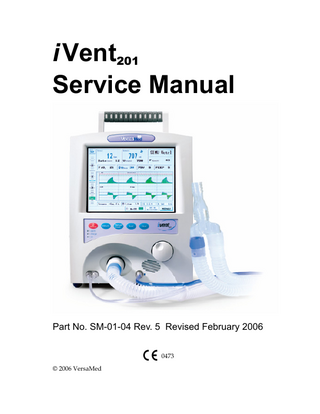
i Vent201 Service Manual
Part No. SM-01-04 Rev. 5 Revised February 2006 0473 © 2006 VersaMed
All Rights Reserved. No part of this document may be photocopied, reproduced, stored in a retrieval system, or transmitted, in any form or by any means, electronic, mechanical, or otherwise without the prior written permission of VersaMed. No warranty of accuracy is given concerning the contents of the information contained in this publication. To the extent permitted by law no liability (including liability to any person by reason of negligence) will be accepted by VersaMed, its subsidiaries or employees for any direct or indirect loss or damage caused by omissions from or inaccuracies in this document. VersaMed reserves the right to change details in this publication without notice. Adaptive Flow® and Adaptive Time® are registered trademarks of VersaMed.
SAFETY:
Before attempting to service or test the iVent201 ventilator please read this manual and the Operator's Manual in their entirety to familiarize yourself with all Cautions and Warnings.
Manufacturer’s Address VersaMed Medical Systems Inc. 2 Blue Hill Plaza Bldg. 2 Pearl River, NY 10965 845-770-2840 Authorized Representative in the European Community Obelis S.A. Avenue de Tervuren 34, Bte 44 B-1040 Brussels Belgium +32-2-732-59.54 Fax: +32-2-732-60.03
Calling For Help If you have a ventilator problem that you cannot solve and you purchased your ventilator directly from VersaMed, call:
800-475-9239 Customer Care and Service Assistance Line or 866-483-6820 (866-iVent201)
If you have a ventilator problem that you cannot solve and you purchased your ventilator from an authorized VersaMed distributor, please contact your distributor directly to report the problem.
NOTE: If this ventilator has not been purchased directly from VersaMed, please ensure that it has been purchased from an authorized distributor of VersaMed. To obtain a list of authorized distributors contact VersaMed at [email protected].
visit our website: www.versamed.com
Table of Contents Section 1: Introduction ... 21 1.1 Intended Use ... 21 1.2 General Description... 22 1.3 Safety Information ... 23 1.3.1 Safety Regulations...24 1.3.2 Technician Safety...24 1.3.2.1 Hazard Notices ...24 1.3.2.2 Calibration and Verification Test ...24 1.3.2.3 Handling PC Boards ...24 1.3.3 Important Safety Considerations ...25 1.4 Labels and Symbols ... 26 1.4.1 Symbols...26 1.4.2 Labels ...27
Section 2: System Specifications... 31 2.1 Specifications... 31 2.1.1 Ventilation Modes ...31 2.1.2 Ventilation Performance and Controlled Parameters...31 2.1.3 Power Supply...32 2.1.4 Oxygen Supply ...32 2.1.5 Size and Weight ...32 2.1.6 Environmental Specifications ...33 2.2 Standards and Safety Requirements ... 33 2.3 Monitoring and Displayed Parameters... 34 2.4 Adjustable Non-Displayed Parameters ... 35
2.5 User Adjustable Alarms ...35 2.6 Additional Alarms and Indicators ...36 2.6.1 Alarms ... 36 2.6.2 Indicators and Icons ... 36
Section 3: Installation and Setup... 37 3.1 External Electrical Supply ...37 3.2 Internal Battery ...38 3.2.1 Battery Charging... 38 3.2.2 Internal Battery Charge Level Indicator... 39 3.3 Oxygen Supply ...39 3.3.1 High Pressure Supply ... 39 3.3.2 Low Pressure Oxygen Supply ... 40 3.4 Patient Circuit ...41 3.4.1 Patient Circuit Connection ... 43 3.5 Filters ...44 3.5.1 Air Inlet Filter ... 44 3.5.1.1 Low Pressure Oxygen Adapter and Filter... 45 3.5.1.2 CBRN Filter... 45 3.5.1.3 Bacterial Filter... 45 3.6 Ventilator Controls ...47 3.6.1 Rotational Control Knob (Encoder) ... 47 3.6.2 Keypad ... 47 3.6.3 LED Indicators ... 48 3.7 Ventilator Operation ...48
Section 4: Theory of Operation ... 49 4.1 Pneumatic Unit ...49
4.1.1 Blower Assembly (Turbine) ...52 4.1.2 Oxygen Blending System ...52 4.1.2.1 O2 Pressure Switch ...53 4.1.2.2 Demand Valve ...53 4.1.2.3 Proportioning Valve...53 4.1.2.4 Valve Controller...54 4.1.2.5 Valve Limit Switch (O2 Microswitch) ...54 4.1.2.6 Oxygen Sensor ...54 4.1.3 Solenoid Valve System ...55 4.1.4 Filters and Mufflers...56 4.1.5 Cooling Fan ...57 4.1.6 Patient Circuit ...57 4.1.6.1 Wye and Flow Sensor ...57 4.1.6.2 Exhalation Valve...57 4.1.6.3 One-way Valve...58 4.2 Electronic Module ... 59 4.2.1 Computer...61 4.2.1.1 System Memory ...61 4.2.1.2 BIOS ...61 4.2.1.3 DiskOnChip®...61 4.2.1.4 RS-232 ...62 4.2.1.5 VGA Display ...62 4.2.1.6 Keyboard...62 4.2.1.7 Ethernet...62 4.2.1.8 PC Watchdog...63 4.2.1.9 Operating System (OS) ...63 4.2.2 Main Board ...63 4.2.2.1 Sensors Interface ...64 4.2.2.1.1 Flow Sensor...64 4.2.2.1.2 Pressure Sensors...64 4.2.2.1.3 Oxygen Sensor...64 4.2.2.1.4 Temperature Sensor ...65
4.2.2.1.5 Battery Voltage ... 65 4.2.2.2 Digital/Analog Interface ... 65 4.2.2.3 Control and Status ... 65 4.2.2.4 Motor Interface ... 65 4.2.2.5 Bus Interface ... 66 4.2.2.6 Solenoids Interface... 66 4.2.2.7 Stepper Interface ... 66 4.2.2.8 Watchdog Timer... 66 4.2.2.9 Remote Alarm... 67 4.2.2.10 SpO2... 67 4.2.3 Zeroing/Purge Board... 67 4.2.4 Switching Board ... 68 4.2.4.1 Switching Block ... 69 4.2.4.2 RF Filter Block ... 69 4.2.4.3 Protective Devices... 69 4.2.4.4 Battery Charger Block ... 70 4.2.4.5 5V Output DC/DC Converter ... 70 4.2.4.6 Power On/ Off Switching... 70 4.2.4.7 Status Block... 70 4.2.4.8 Motor Driver... 70 4.2.4.9 External DC/DC Converter and External DC Source ... 71 4.2.4.10 Auxiliary Power Supplies... 71 4.2.5 Power Supply (AC/DC Converter) ... 71 4.2.5.1 Cooling Fan... 71 4.3 LCD Display ...71 4.4 Interface Board ...72 4.5 Power Pack ...72 4.5.1 Gas Gauge ... 73
Section 5: Maintenance and Calibration ... 75 5.1 Cleaning and Routine Maintenance ...75 5.2 Preventive Maintenance...76
5.2.1 500 Hour PM ...76 5.2.2 1500 Hour PM ...77 5.2.3 Annual PM ...78 5.2.4 15000 Hour PM ...78 5.3 Storage ... 79 5.4 Calibration Procedure ... 79 5.4.1 Purpose ...79 5.4.2 Scope ...80 5.4.3 Tools & Equipment ...80 5.4.4 Initialization ...80 5.4.5 Procedure...80 5.4.5.1 Enter Calibration Menu ...81 5.4.5.2 Zero Sensors ...82 5.4.5.3 Pressure Sensors ...82 5.4.5.4 PEEP-RPM ...83 5.4.5.5 Flow Sensor ...84 5.4.5.6 Volume ...85 5.4.5.7 O2 System...85 5.4.5.8 Save New Calibration ...86
Section 6: Ventilator Test Procedures ... 89 6.1 Operational Verification Test ... 89 6.1.1 Purpose ...89 6.1.2 Scope ...89 6.1.3 Tools & Equipment ...89 6.1.4 Initialization ...89 6.1.5 Procedure...89 6.2 Ventilator Verification Test (VVT) Procedure... 91 6.2.1 Purpose ...91
6.2.2 Scope... 91 6.2.3 Tools & Equipment... 91 6.2.4 Initialization... 91 6.2.5 Procedure ... 91 6.2.5.1 Alarm Sound Tests... 92 6.2.5.2 Pressure Tests ... 94 6.2.5.3 Flow Tests ... 95 6.2.5.4 O2 Tests ... 95 6.2.5.5 Battery Test ... 96 6.2.5.6 Watchdog Timer Tests... 96 6.3 Functional Verification Test Procedure...98 6.3.1 Purpose... 98 6.3.2 Scope... 98 6.3.3 Tools & Equipment... 98 6.3.4 Initialization... 99 6.3.5 Procedure ... 100 6.3.5.1 O2 Delivery and Linearity... 100 6.3.5.2 100% O2 (Suction) Test ... 101 6.3.5.3 Safety Alarms Test ... 102 6.3.5.3.1 High Pressure Alarm ... 102 6.3.5.3.2 Apnea Alarm... 103 6.3.5.3.3 Tube Disconnect Alarm... 103 6.3.5.3.4 Patient Disconnect Alarm ... 104 6.3.5.3.5 Sensor Disconnect Alarm ... 105
Section 7: Service Procedures... 107 7.1 Software Upgrade Procedure ...107 7.1.1 Purpose... 107 7.1.2 Scope... 107 7.1.3 Tools & Equipment... 107
7.1.4 Procedure...107 7.2 Technical Logs Download... 110 7.2.1 Purpose ...110 7.2.2 Scope ...110 7.2.3 Tools & Equipment ...110 7.2.4 Procedure...111 7.3 Option Package Update... 112 7.3.1 Purpose ...112 7.3.2 Scope ...112 7.3.3 Tools & Equipment ...112 7.3.4 Procedure...112 7.4 Ventilator Disassembly and Assembly ... 114 7.4.1 Purpose ...114 7.4.2 Scope ...114 7.4.3 Enclosure Disassembly & Assembly ...114 7.4.3.1 Tools & Equipment ...114 7.4.3.2 Enclosure Disassembly ...115 7.4.3.3 Enclosure Assembly ...117 7.4.4 Electronic Module Removal and Installation...118 7.4.4.1 Tools & Equipment ...118 7.4.4.2 Electronic Module Removal...118 7.4.4.3 Electronic Module Installation...120 7.4.5 Electronic Module Disassembly and Assembly...121 7.4.5.1 Electronic Module Cover Removal and Installation ...121 7.4.5.1.1 Tools & Equipment...121 7.4.5.1.2 Electronic Module Cover Removal ...121 7.4.5.1.3 Electronic Module Cover Installation ...122 7.4.5.2 Zeroing/ Purge Board Removal and Installation...123 7.4.5.2.1 Tools & Equipment...123
7.4.5.2.2 Zeroing/ Purge Board Removal ... 123 7.4.5.2.3 Zeroing/ Purge Board Installation ... 124 7.4.5.3 Main Board Removal and Installation ... 125 7.4.5.3.1 Tools & Equipment ... 125 7.4.5.3.2 Main Board Removal ... 125 7.4.5.3.3 Main Board Installation... 128 7.4.5.4 CPU Board Removal and Installation ... 128 7.4.5.4.1 Tools & Equipment ... 128 7.4.5.4.2 CPU Board Removal ... 129 7.4.5.4.3 CPU Board Installation... 131 7.4.5.5 Power Supply Board Removal and Installation ... 131 7.4.5.5.1 Tools & Equipment ... 131 7.4.5.5.2 Power Supply Board Removal ... 131 7.4.5.5.3 Power Supply Board Installation... 133 7.4.5.6 Switching Board Removal and Installation... 133 7.4.5.6.1 Tools & Equipment ... 133 7.4.5.6.2 Switching Board Removal... 133 7.4.5.6.3 Switching Board Installation ... 135 7.4.6 Pneumatic Unit Removal and Installation ... 136 7.4.6.1 Tools & Equipment ... 136 7.4.6.2 Pneumatic Unit Removal ... 136 7.4.6.3 Pneumatic Unit Installation... 137 7.4.7 LCD Assembly Removal and Installation... 140 7.4.7.1 Tools and Equipment ... 140 7.4.7.2 LCD Assembly Removal... 140 7.4.7.3 LCD Assembly Installation... 141 7.4.8 Interface Board Removal and Installation... 142 7.4.8.1 Tools & Equipment ... 142 7.4.8.2 Interface Board Removal... 142 7.4.8.3 Interface Board Installation ... 143 7.4.9 Power Pack Disassembly and Assembly... 144 7.4.9.1 Tools & Equipment ... 144 7.4.9.2 Power Pack Disassembly ... 144
7.4.9.3 Power Pack Assembly...145 7.4.10 O2 Sensor Removal and Installation ...146 7.4.10.1 Tools & Equipment ...146 7.4.10.2 O2 Sensor Removal ...146 7.4.10.3 O2 Sensor Installation...146 7.5 Battery Gas Gauge Initialization Procedure ... 147 7.5.1 Purpose ...147 7.5.2 Scope ...147 7.5.3 Tools & Equipment ...147 7.5.4 Procedure...147
Section 8: Troubleshooting... 149 8.1 Troubleshooting Guide ... 149 8.2 Diagnostics and Repairs ... 154 8.2.1 Power Switch ...154 8.2.2 Demand Valve ...156 8.2.3 Pressure Switch...157 8.2.4 Valve Limit Switch (O2 Microswitch)...158 8.2.5 Flow Sensor Leak...160 8.2.5.1 Root Cause - Pneumatic vs. Electronic ...162 8.2.5.2 Isolation of Internal Tube Leak...162 8.2.5.3 Blower Pressure & Exhalation Valve Control ...163 8.2.5.4 Negative (-) Flow Port vs. Positive (+) Flow Port ...163 8.2.5.5 Negative (-) Flow Port & Patient Pressure...164 8.2.5.6 Positive (+) Flow Port ...167 8.3 Exhale VT Accuracy... 168 8.3.1 Inhale VT Accuracy...168 8.3.2 Exhale VT Accuracy Interferences ...168 8.3.3 Leakage ...169
8.3.4 Velocity... 169 8.3.5 MAQUET (Siemens 190) Test lung ... 170 8.4 Miscellaneous Issues...171 8.4.1 Black Screen ... 171 8.4.2 Fails Calibrate Flow Sensor ... 171 8.4.3 Erratic O2 Control ... 171 8.4.4 Erratic Exhale Tidal Volumes ... 172 8.4.5 Low Pressure During Calibration or VVT ... 172 8.5 Setting Up the Ventilator for Static Pressure...172
Appendix A: Parts and Accessories... 175 Appendix B: Service Report Form ... 177 Appendix C: Technician Tool Utility Software... 181 C.1 Purpose ...181 C.2 Scope...181 C.3 Tools & Equipment ...181 C.4 Procedure ...181 C.4.1 Software Installation... 181 C.4.2 Initial Setup... 182 C.4.3 Overview... 184 C.4.4 Read All Parameters ... 184 C.4.5 Card Number... 185 C.4.6 Read O2 Raw Value... 185 C.4.7 Read Battery LMD ... 186 C.4.8 Reset Battery Gas Gauge... 187 C.4.9 Set Machine Serial Number... 188
C.4.10 SetUp Button ...189
Appendix D: Wiring and Cables... 191 Index... 195
Illustrations Figure 1-1: The iVent201 (front view) ... 22 Figure 1-2: The iVent201 (rear view)... 23 Figure 3-1: External AC and DC Power ... 38 Figure 3-2: Oxygen Inlet Connector... 40 Figure 3-3: Low Pressure Oxygen Supply System ... 41 Figure 3-4: Patient Circuit ... 42 Figure 3-5: Patient Circuit Connection ... 44 Figure 3-6: iVent201 Filters ... 46 Figure 3-7: Ventilator Controls ... 47 Figure 4-1: Pneumatic Unit ... 50 Figure 4-2: Pneumatic Unit Overview... 51 Figure 4-3: Electronic Module ... 59 Figure 4-4: Ventilator Overview... 60 Figure 5-1: Cooling Vent (left) and Cooling Air Inlet Filter (right)... 77 Figure 5-2: Entering the Maintenance Menu... 81 Figure 5-3: Entering the Calibration Menu... 81 Figure 5-4: Zero Sensors ... 82 Figure 5-5: Calibrate Pressure Sensors ... 83 Figure 5-6: Calibrate PEEP-RPM... 84 Figure 5-7: Calibrate Flow Sensor ... 84 Figure 5-8: Calibrate Volume... 85 Figure 5-9: Calibrate O2 System... 86 Figure 5-10: Save Calibration... 87 Figure 6-1: OVT #1 ... 90 Figure 6-2: OVT #2 ... 90 Figure 6-3: Entering the Maintenance Window... 93 Figure 6-4: Entering VVT ... 93
Figure 6-5: Pressure Tests ...94 Figure 6-6: Pressure Test Results ...94 Figure 6-7: Flow Tests...95 Figure 6-8: O2 Tests (21%) ...95 Figure 6-9: O2 Tests (100%) ...96 Figure 6-10: Battery Test ...96 Figure 6-11: Reconnect AC Power ...97 Figure 6-12: Watchdog Timer Tests...97 Figure 6-13: VVT Test Results ...98 Figure 6-14: External O2 Analyzer Test Setup ...99 Figure 6-15: Internal O2 Measurement...100 Figure 6-16: 100% O2 (Suction) Mode ...101 Figure 6-17: High Pressure Alarm ...102 Figure 6-18: Apnea Alarm ...103 Figure 6-19: Tube Disconnect Alarm...104 Figure 6-20: Patient Disconnect Alarm ...104 Figure 6-21: Sensor Disconnect Alarm...105 Figure 7-1: RS-232 Cable to iVent201 ...108 Figure 7-2: Upgrade iVent201 Software Screen ...108 Figure 7-3: Upgrade iVent201 PC Application Screens...109 Figure 7-4: ivDownload PC Application Screens...111 Figure 7-5: Update Package Key...113 Figure 7-6: Enclosure (Rear View) #1...116 Figure 7-7: Front Enclosure (Inside View) #1 ...116 Figure 7-8: Rear Enclosure (Inside View) #1...117 Figure 7-9: Enclosure (Rear View) #2...119 Figure 7-10: Rear Enclosure (Inside View) #2...120 Figure 7-11: EM Cover Screw Locations...122 Figure 7-12: EM Sensor Tubing Cover Screw Locations ...122 Figure 7-13: EM with Cover Removed to Show Zeroing/ Purge PCB ...124 Figure 7-14: Electronic Module (Rear View) – Remote Alarm Area ...125
Figure 7-15: Main Board ... 127 Figure 7-16: CPU Board ... 130 Figure 7-17: EM with Side Cover Lowered to Show Power Supply... 132 Figure 7-18: EM with Side Cover Lowered to Show Switching Board... 134 Figure 7-19: Switching Board Screw Locations... 135 Figure 7-20: Rear Enclosure (Inside View) #3 ... 137 Figure 7-21: O2 Mixer Cam to Mid Point Position ... 138 Figure 7-22: PU Ground Point Locations ... 139 Figure 7-23: Front Enclosure (Inside View #2)... 141 Figure 7-24: Front Enclosure (Inside View) #3... 143 Figure 7-25: Power Pack (Rear View) ... 145 Figure 7-26: Power Pack (Removed)... 145 Figure 8-1: Power Switch Assembly ... 155 Figure 8-2: O2 Inlet Pipe and Demand Valve ... 157 Figure 8-3: PU Main Connector (Front View) - Pressure Switch Pinout... 158 Figure 8-4: O2 Mixer (Top View) ... 159 Figure 8-5: Main Connector (Front View) - Microswitch Pinout ... 160 Figure 8-6: Pneumatic Sensors Connections... 161 Figure 8-7: Test Setup (Unit Operating Disassembled) ... 166 Figure 8-8: Flow Graphs (Occluding the Negative Flow Sensor Port) ... 167 Figure 8-9: Flow Graphs (Occluding the Positive Flow Sensor Port) ... 167 Figure 8-10: Flow Graphs (High Velocity Exhale)... 170 Figure 8-11: Test Lung 190 and iVent201 Waveforms ... 171 Figure C-1: Password Entry Box ... 182 Figure C-2: Creating File Message Box ... 183 Figure C-3: Select Communication Port... 183 Figure C-4: Main Screen ... 184 Figure C-5: O2 Raw Value Too Low Pop-Up ... 186 Figure C-6: LMD Value Too Low Pop-Up... 187 Figure C-7: LMD Reset Verification Pop-Up... 188 Figure C-8: Set Machine Serial Number... 189
Figure D-1: iVent201 Wiring Diagram (Page 1)...193 Figure D-2: iVent201 Wiring Diagram (Page 2)...194
Tables Table 2-1: Displayed Parameters and Indicators During Ventilation... 34 Table 3-1: Internal Battery Charge Level Indicator ... 39 Table 5-1: Cleaning and Routine Maintenance ... 75 Table 5-2: Preventive Maintenance Schedule... 76 Table 8-1: Troubleshooting Guide ... 150
Section 1: Introduction 1.1 Intended Use This Service Manual describes the service, maintenance and test procedures for the iVent201 (hardware version 1.4). It is intended to ensure optimal functional operation and safety of the device. This Service Manual should only be used by authorized VersaMed trained technicians. This Service Manual must be used in conjunction with the Operator's Manual (OM-01-04) and is complementary to it. The contents of this document are not binding. If any significant difference is found between the product and this document, please contact VersaMed for further information. VersaMed reserves the right to modify the product without amending this document or advising the user.
IMPORTANT: Technical information is supplied in this manual that is intended to facilitate a complete understanding of the ventilator's structure and function. Not every component or subsystem discussed in this manual is accessible or repairable in the field. The iVent201 was designed to provide easy access to serviceable areas of the ventilator. Whenever possible, this manual describes the practical (hands-on) aspect of a component or system.
Issued: 23-Feb-06
21