Pro-Med Patient Lifting
INVACARE Patient Lifting & Transfer
Birdie and Birdie Compact User Manual Sept 2016
User Manual
50 Pages
Preview
Page 1
Invacare®
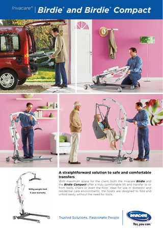
Birdie® and Birdie® Compact
A straightforward solution to safe and comfortable transfers 180kg weight limit 5 year warranty
With maximum space for the client, both the Invacare Birdie and the Birdie Compact offer a truly comfortable lift and transfer to or from beds, chairs or even the floor. Ideal for use in domestic and residential care environments, the hoists are designed to fold and unfold easily without the need for tools.
Invacare®
Birdie® and Birdie® Compact
Comfort and ease of use combined The high boom maximises space for the client even when the hoist is in the highest position. This gives an ergonomic lift and transfer as the client can be easily rotated 360°, which makes positioning much easier for the carer. The optimisation of space allows increased space in front of the actuator, reducing the risk of injury to the client's knees.
Ease of handling: simple to fold, unfold and dismantle without tools Handling the hoist has been made as smooth and easy as possible as the hoists can easily be folded and unfolded without the need for tools. Hoists take up minimal space when stored and are easy to push and transport. If required, the mast and boom can be easily detached from the base (no tools required).
TÜV-certification for maximum security For total security, the folding mechanism has a snap-lock system, thus minimizing the risk of accident. The Birdie and Birdie Compact are CE-certified in line with the Medical Device Directive 93/42/ECC.
To ensure the hoists comply with EN ISO 10535 (the European standard for hoists) the hoist has been rigorously tested both by Invacare and the German TÜV institute, an accredited external body.
Features and Options
Long boom – high user comfort The client can easily be rotated and positioned. No risk of injuries to the knees.
Easy to fold and dismantle Ease of transport and storage. No tools required when folding / unfolding or when dismantling the hoist.
Snap lock Optimal security.
Emergency stop, lowering and integrated charger Manual or electric emergency lowering (compact version only electric lowering). Control box is supplied with detachable or fixed battery.
Invacare®
Birdie® and Birdie® Compact
Features and Options
Clip on spreader bar Easy to change the spreader bar – just twist the safety catch, press to open - and then detach/attach the spreader bar.
Mounted spreader bar Correctly and safe positioning of the spreader bar. A locking carabiner offers exceptional security.
Manual leg spread Simply step on the pedal to adjust the leg spread.
Handle for leg spread Handle can easily be attached to operate the manual leg spread.
Electrical leg spread Available for Invacare Birdie models only.
2 point quick release spreader bars Easy to attach and detach. Available widths: 35 cm, 45 cm, 55 cm.
Push bar and hand control Superior ergonomics for carers.
Castors 100 mm castors (braking castor is shown).
Scale If needed, a Homecare scale is available approved, according to medical standard EN 45501.
4 point quick release spreader bars Easy to attach and detach. Available widths: 45 cm and 55 cm.
Invacare®
Birdie® and Birdie® Compact
Technical data
kg g Birdie
124 cm
64 cm
42 kg
44,5 - 171 cm
10 cm
Birdie Compact
109 cm
52 cm
36 kg
52,5 - 161,5 cm
10 cm
Birdie
101 cm
180 kg
40 cycles
2,9 Ah
140 cm
Birdie Compact 84,5 cm
150 kg
40 cycles
2,9 Ah
107 cm
All measures are taken with 75 mm castors and 2 point spreaderbar. For 100 mm castors add 1,5 cm for height measures and 2 cm for width.
Frame colour
Warranty
5 year warranty: Frame Actuator Control box Light grey / Dark grey
2 year warranty: Hand control
Invacare Limited Pencoed Technology Park Pencoed - Bridgend CF35 5AQ United Kingdom Tel: +44 1656 776 222 Fax: +44 1656 776 220 E-mail: [email protected] Sales Order E-mail: [email protected] www.invacare.co.uk Invacare Ireland Ltd Unit 5 - Seatown Business Campus Seatown Road - SWORDS - County Dublin - Ireland Tel. +353 1 8107084 Fax +353 1 8107085 Email: [email protected] www.invacare.ie © 2016 Invacare International Sàrl All rights reserved. All information quoted is believed to be correct at time of print. Invacare reserves the right to alter product specifications without prior consultation.
The Invacare Birdie and Birdie Compact are part of the Safe Patient Handling range.
Birdie - UK - 01/2016 - 1504431
Invacare®Birdie™ Birdie™, Birdie™Compact
This manual MUST be given to the user of the product. BEFORE using this product, read this manual and save for future reference.
en
Portable Patient Lift User Manual... 4
de
Mobiler Patientenlifter Gebrauchsanweisung... 50
es
Grúa portátil para pacientes Manual del usuario... 98
fr
Lève-personne portatif Manuel d'utilisation...146
it
Sollevatore portatile Manuale d’uso...196
nl
Mobiele patiëntlift Gebruiksaanwijzing...246
pt
Elevador de transferência móvel Manual de utilização...294
Contents This manual MUST be given to the user of the product. BEFORE using this product, read this manual and save for future reference. 1 General... 5 1.1 Introduction... 5 1.2 Symbols in this manual... 5 1.3 Intended Use... 5 1.4 Scope of delivery... 6 1.5 Service Life... 7 1.6 Warranty Information... 7 2 Safety... 8 2.1 Safety information... 8 2.2 Operating Information... 8 2.2.1 General... 8 2.2.2 Pinch Points and Positioning... 9 2.3 Radio Frequency Interference... 9 2.4 Product labeling... 9 3 Components... 11 3.1 Main parts of the lift... 11 3.2 Accessories... 12 4 Setup... 13 4.1 Safe Assembly... 13 4.2 Assembling the Mast to the Base... 13 4.3 Installing the actuator to the boom... 14 4.4 Mounting the hanger bar... 14 4.5 Disassembling of the lift... 15 4.6 Checking the service light... 15
5 Usage... 17 5.1 Introduction... 17 5.2 Raising/Lowering the Lift... 17 5.2.1 Raising/Lowering an Electric Lift... 17 5.3 Closing/Opening Legs... 17 5.3.1 Closing/Opening Electric Legs... 17 5.3.2 Closing/Opening legs manually... 18 5.4 Performing an Emergency Stop... 18 5.5 Activating an Emergency Release... 18 5.6 Charging the battery... 20 6 Lifting the Patient... 22 6.1 Safe Lifting... 22 6.2 Preparing to Lift... 23 6.3 Attaching the Slings to the Lift... 25 6.4 Lifting and Transferring the Patient... 27 6.4.1 Floor Transfers (Lifting from the Floor)... 28 6.4.2 Commode Transfer Guidelines... 30 6.4.3 Bed Transfer... 31 6.4.4 Wheelchair Transfer... 31 7 Maintenance... 33 7.1 Maintenance and Safety Inspection... 33 7.1.1 Safety inspection checklist... 35 7.2 Lubricating the Lift... 36 7.3 Cleaning the Sling and Lift... 36 7.4 Checking and Tightening Mast Pivot Bolt... 37 7.5 Checking the carabiner and its mounting... 37 7.6 Replacing the Hanger Bar... 37 8 After Use... 39 8.1 Transportation and Storage... 39 8.2 Disposal... 39 8.3 Reuse... 39
9 Troubleshooting... 40 9.1 Identifying and repairing faults... 40 10 Technical data... 42 10.1 Dimensions and weight... 42 10.2 Electrical system... 43 10.3 Environmental conditions... 44 10.4 Materials... 44 10.5 Electromagnetic compliance (EMC) information... 44 10.6 Electromagnetic compliance (EMC)... 45
General
1 General
This product complies with Directive 93/42/EEC concerning medical devices. The launch date of this product is stated in the CE declaration of conformity.
1.1 Introduction Thank you for choosing an Invacare product. This user manual contains important information about the handling of the product. In order to ensure safety when using the product, read the user manual carefully and follow the safety instructions.
Manufacturer of the product.
1.3 Intended Use
Please note that there may be sections in this user manual, which are not relevant to your product, since this manual applies to all available models (on the date of printing). If not otherwise stated, each section in this manual refers to all models of the product.
WARNING! Risk of Falling The Invacare mobile patient lift is NOT a transport device. It is intended to transfer an individual from one resting surface to another (such as a bed to a wheelchair). Invacare slings and patient lift accessories are specifically designed to be used in conjunction with Invacare patient lifts.
1.2 Symbols in this manual Symbols and signal words are used in this manual and apply to hazards or unsafe practices which could result in personal injury or property damage. See the information below for definitions of the signal words. WARNING Indicates a hazardous situation that could result in serious injury or death if it is not avoided. CAUTION Indicates a hazardous situation that could result in minor or slight injury if it is not avoided. IMPORTANT Indicates a hazardous situation that could result in damage to property if it is not avoided. Tips and Recommendations Gives useful tips, recommendations and information for efficient, trouble-free use. 1575480-D
Mobile patient lifts are battery-powered transfer devices, designed to be used in most of the common lifting situations in hospitals, nursing facilities and domestic areas, for example:
• • •
Between the bed and a wheelchair To and from the toilet Lowering and raising patients to/from the floor
The mobile patient lift can be used to transfer and position completely or partially immobile patients, who cannot be transferred with other types of lifts or transfer aids. All position changes are possible without assistance of the patient. The mobile patient lift is only intended to lift patients up to the maximum weight limit stated in technical data. There are no known contraindications for this product. 5
Invacare®Birdie™
A
Selecting the appropriate slings and accessories for each individual is important to assure safety when using a patient lift. See Invacare’s sling and accessory user manuals for further information on those devices. Invacare recommends that the patient be transferred to a shower chair or other means for bathing. The mobile patient lift can be turned (rotated) in place for transfers with limited floor space.
B
D
1.4 Scope of delivery The items listed in the tables are included in your package. Slings and additional hanger bars are sold separately. Depending on your model, the wall charger may be sold separately.
6
C
A
Lift (1 piece)
B
Battery (1 piece)
C
Hand control (1 piece)
D
Hanger bar (1 piece)
E
Mains cable (1 piece)
F
User Manual (1 piece)
1575480-D
General
G
Manual leg spreader handle (1 piece, optional)
H
Sling (1 piece, optional)
1.5 Service Life WARNING! Risk of Injury or Damage The product has been tested for the service life stated in this manual. Use of the product beyond this time period may cause product damage and injury. – Only use the product for the service life stated in this manual. DO NOT exceed the service life of the product. – Remove the product from service when the service life has been met. DO NOT continue to use the product. – Perform all maintenance according to the recommended schedule in this manual.
Number of lifts per day
Service life of actuator (in years)
6
4
7–9
3
10–13
2
14–27
1
1.6 Warranty Information Terms and conditions of the warranty are part of the general terms and conditions particular to the individual countries in which this product is sold. Contact information for your local Invacare office is located inside the back cover of this manual.
The mobile patient lift has an expected lifetime of 8 years when used in accordance with safety instructions, maintenance intervals and correct use, stated in this manual. The effective product lifetime can vary according to frequency and intensity of use.
Actuator Service Life Number of lifts per day
Service life of actuator (in years)
1–2
10
3
9
4
6
5
5
1575480-D
7
Invacare®Birdie™
2 Safety 2.1 Safety information WARNING! – Do not use this product or any available optional equipment without first completely reading and understanding these instructions and any additional instructional material such as user manuals, service manuals or instruction sheets supplied with this product or optional equipment. If you are unable to understand the warnings, cautions or instructions, contact a healthcare professional, dealer or technical personnel before attempting to use this equipment otherwise, injury or damage may occur. The information contained in this document is subject to change without notice. Check all parts for shipping damage before using. In case of damage, Do not use the equipment. Contact the dealer or Invacare representative for further instructions.
2.2 Operating Information This section of the manual contains general safety information about your product. For specific safety information, refer to the appropriate section of the manual and procedures within that section. For instance, for safety information related to assembling the lift, refer to the Setup section of the manual.
8
2.2.1 General WARNING! Risk of Falling Do not attempt any transfer without approval of the patient’s physician, nurse or medical assistant. Thoroughly read the instructions in this User Manual, observe a trained team of experts perform the lifting procedures and then perform the entire lift procedure several times with proper supervision and a capable individual acting as a patient. – Use common sense in all lifts. Special care must be taken with people with disabilities who cannot cooperate while being lifted. – Use steering handle on the mast at all times to push or pull the patient lift. – Be sure to check the sling attachments each time the sling is removed and replaced, to ensure that it is properly attached before the patient is removed from a stationary object (bed, chair or commode). WARNING! – The patient lift can be used indoors or outdoors. If the patient lift is used in the area of a shower or bath, ensure that the patient lift is wiped clean of any moisture after use. – Periodically inspect all components of the patient lift for signs of corrosion. Replace all parts that are corroded or damaged.
1575480-D
Safety
2.2.2 Pinch Points and Positioning
WARNING! Risk of Injury Pinch points are present in several locations on the lift and fingers could be pinched. The hanger bar can move suddenly and cause injury. – Always keep hands and fingers clear of moving parts. – When positioning lift, be aware of the position of the hanger bar and the patient.
2.3 Radio Frequency Interference WARNING! Risk of Injury or Damage Most electronic equipment is influenced by Radio Frequency Interference (RFI). CAUTION should be exercised with regard to the use of portable communication equipment in the area around such equipment, otherwise injury or damage may occur. If RFI causes erratic behavior: – PUSH the Red Power Switch OFF IMMEDIATELY. – DO NOT turn the Power Switch ON while transmission is in progress.
2.4 Product labeling Label location 180 kg
XL L M 1580353 Rev A
S Invacare Portugal, Lda Rua Estrada Velha 949 4465-784 Leça do Balio, Portugal
XXXXXX XXXXX_XX XXXXXXXXXXXXX
XS ISO 10535
Xxxxxxx xxxxx xxx Xxxxxxx xxxxx xxx Xxxxxxx xxxxx xxx Xxxxxxx xxxxx xxx Xxxxxxx xxxxx xxx = xxx kg
YYYY -MM
1575480-D
Birdie
9
Invacare®Birdie™
Symbols on the label
Safe Working Load
Emergency stop / Emergency release Class II equipment Raise/lower the boom
Open/close legs
Open/close legs manually
Type B applied part This product complies with Directive 93/42/EEC concerning medical devices. The launch date of this product is stated in the EC declaration of conformity. WEEE conform.
Caster lock Audible tone when battery low Read Manual Manufacturer address Date of manufacture Type Reference Number Serial Number
10
1575480-D
Components
3 Components 3.1 Main parts of the lift E F L
I R
B
Leg
C
Caster
D
Rear caster with brake
E
Boom
F
Mast
H
G
Hanger bar
K J
G
H
Hook for sling
I
Carabiner
J
Actuator
K
Manual emergency lowering handle
L
Control unit with Battery
M
Emergency Stop
N
Hand control
O
Locking pin
P
Steering handle
Q
Foot pedal for leg spreader
R
Quick release pin
N
D
Base
P
M
Q O
A
A
B
C
Leg spreader handle (optional) Motor for electrical operation of legs (optional)
1575480-D
11
Invacare®Birdie™
3.2 Accessories CAUTION! Compatibility of slings and hanger bars / strap hooks Invacare® uses a "Loop and Coat Hanger Bar / Strap Hook System" as do many other manufacturers. Therefore other suitable patient transfer systems (slings), manufactured by other companies, can be used on the Invacare patient lift range as well. However we do recommend: – A risk assessment is always to be carried out by a professional prior to issuing lifting equipment. It is important that the Task, Individual, Load, Environment and Equipment are considered in the risk assessment. – Always choose the sling design and size according to the patient’s weight, size and physical ability whilst considering the type of transfer to be carried out. – Do only use slings that are suitable for a "Loop and Coat Hanger Bar / Strap Hook System". – Do not use slings for "Keyhole Hanger Bar" or for "Tilting Frame Hanger Bar" designs.
12
Available accessories • • • •
4 point hanger bar (“Coat Hanger Bar System”), 45 or 55 cm wide 2 point hanger bar (“Coat Hanger Bar System”), 35, 45 or 55 cm wide Scale to be mounted with the hanger bar Handle for leg spread
Sling models for "Loop and Coat Hanger Bar System":
• • • •
Full body support slings – without head support Full body support slings –with head support Slings for dress/toileting – with or without head support Slings for amputee
1575480-D
Setup
4 Setup 4.1 Safe Assembly WARNING! Risk of Injury Improper assembly may cause injury or damage. – Assembly MUST be performed only by qualified personnel. – Use only Invacare parts in the assembly of this patient lift. The base legs, the mast, boom, pump assembly and the hanger bar are manufactured to specifications that assure correct alignment of all parts for safe functional operation. – DO NOT overtighten the mounting hardware. This will damage the mounting bracket.
4.2 Assembling the Mast to the Base WARNING! – The mast may be folded for storage or transporting. Each time the mast is folded, the mast MUST be properly secured to the base assembly. – Check all parts for visible defects or damage before assembly. In case of any damage, do not use the product and contact Invacare®. – Make sure the emergency stop is activated before assembly or disassembly. – Take care when lifting components during assembly. Some parts are heavy. Always remember to adopt the correct lifting position. Perform unpacking and assembly operation at floor level.
There are no tools required to assemble the patient lift. If there are any issues or questions during assembly, contact a local Invacare representative. Refer to the contact information on the last page in this manual.
1575480-D
13
Invacare®Birdie™
1. 2.
Lock both rear casters B. Remove the locking pin A. Raise the mast assembly C to an upright position by stepping with one foot on the leg D and pulling the handle bar E upwards until it locks in place.
1. 2. 3.
Remove the quick release pin A from the boom mounting bracket B. Place the actuator C in the boom mounting bracket and align the holes. Reinstall the quick release pin and secure it with the clip D facing forwards. Make sure that the quick release pin is completely inserted and fixed with the clip facing forwards, as shown in the figure, step 3.
4.4 Mounting the hanger bar
3.
Reinstall the locking pin A through the mast G and base F. Ensure that the locking pin is correctly inserted.
4.3 Installing the actuator to the boom Before installing the actuator, loosen the hanger bar by pulling it downwards out of the welded fork on the mast. 1.
14
2.
3.
WARNING! Risk of injury – Use only hanger bars made for this lift (“Coat Hanger Bar System”). – Make sure the hanger bar is suitable for the patient and the actual lift or transfer required. – Check that the hanger bar is firmly attached to the carabiner. The safety catch of the carabiner must be closed after the hanger bar is mounted and before lifting the patient. There is risk of detachment if the safety catch is not correctly closed.
1575480-D
Setup
4.6 Checking the service light ( Jumbo Care control unit only) CAUTION! – Each time the lift is assembled, and before using the lift, the service light should be checked. – The service light should only be reset by a qualified technician and must never be reset by untrained personnel.
1. 2. 3.
Open the carabiner A by first twisting the safety catch B and then pressing it backwards with one hand. Hold the safety catch in the open position and attach the hanger bar C to the carabiner with the other hand. Release the safety catch and move the hanger bar to the lowest point of the carabiner.
4.5 Disassembling of the lift 1. 2. 3. 4.
5. 6.
Remove optional leg spreader handle if attached. Lower the boom and narrow both legs completely. Activate the emergency stop button and apply castor brakes. Remove the pipe pin and the motor piston from the boom, reinstall the pipe pin in the piston end, and lock the motor into the clips on the mast. Attach the hanger bar into the welded fork on the mast. Remove the locking pin from the base of the mast, release the safety latch, lower the mast, and relocate the locking pin into the mast near the suspension axle of the mast.
A C
1. 2.
Examine the control box A to see if the service light C is flashing. When service light is not flashing, the lift is ready for use. When service light is flashing, refer to the table:
The lift can now be located in the packaging box, pulled on the rear wheels, or parked in an upright position with the mast/boom assembly pointing upwards. 1575480-D
15
Invacare®Birdie™
Initial Assembly
A qualified technician has to reset the service light: 1. 2.
3. Reassembly
16
Locate the hand control. Press and hold the UP button and the DOWN button at the same time for five seconds. You will hear a sound when the service light has been reset.
The lift requires service. Contact your local Invacare dealer or representative for service.
1575480-D
Usage
5 Usage
Release the button to stop raising or lowering the lift.
5.1 Introduction The operation of the patient lift is an easy and safe procedure. Before using the lift with a patient, refer to the following procedures for safety information and instruction: • Operating Information in the Safety section • Lifting and Transferring the Patient in the Lifting the Patient section
5.2 Raising/Lowering the Lift WARNING! Risk of Injury The lift could tip and endanger the patient and assistants. – Invacare does recommend that the rear casters be left unlocked during lifting procedures to allow the patient lift to stabilize itself when the patient is initially lifted from a chair, bed or any stationary object.
5.2.1 Raising/Lowering an Electric Lift The hand control is used to raise or lower the lift. 1.
2.
1575480-D
To raise the lift - Press and hold the UP A button to raise the boom and the patient. To lower the lift - Press and hold the DOWN B button to lower the boom and the patient.
5.3 Closing/Opening Legs WARNING! Risk of Injury The lift could tip and endanger the patient and assistants. – The legs of the lift must be in the maximum open position for optimum stability and safety. If it is necessary to close the legs of the lift to maneuver the lift under a bed, close the legs of the lift only as long as it takes to position the lift over the patient and lift the patient off the surface of the bed. When the legs of the lift are no longer under the bed, return the legs of the lift to the maximum open position.
5.3.1 Closing/Opening Electric Legs The hand control is used to open or close the legs of the base. 1. 2.
To close the legs, press and hold the legs closed button A. To open the legs, press and hold the legs open button B.
The legs will stop moving when the button is released.
17