Pro-Med Patient Lifting
INVACARE Patient Lifting & Transfer
Birdie EVO, Birdie EVO COMPACT, Birdie EVO PLUS, Birdie EVO XPLUS User Manual Sept 2020
Birdie EVO, Birdie EVO COMPACT, Birdie EVO PLUS, Birdie EVO XPLUS User Manual Sept 2020
36 Pages
Preview
Page 1
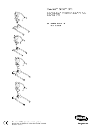
Invacare® Birdie® EVO Birdie® EVO, Birdie® EVO COMPACT, Birdie® EVO PLUS, Birdie® EVO XPLUS
en Mobile Patient Lift User Manual
This manual MUST be given to the user of the product. BEFORE using this product, this manual MUST be read and saved for future reference.
©2020 Invacare Corporation All rights reserved. Republication, duplication or modification in whole or in part is prohibited without prior written permission from Invacare. Trademarks are identified by ™ and ®. All trademarks are owned by or licensed to Invacare Corporation or its subsidiaries unless otherwise noted.
Contents
7.3 Folding the mast... 25 7.4 Mast extension for upright positioning... 25
1 General... 1.1 Introduction... 1.1.1 Symbols in this Document... 1.2 Service Life... 1.2.1 Additional information... 1.3 Limitation of Liability... 1.4 Warranty Information... 1.5 Compliance... 1.5.1 Product-specific standards...
4 4 4 4 4 4 4 4 4
2 Safety... 2.1 General safety information... 2.1.1 Pinch points... 2.2 Safety Information on Accessories... 2.3 Safety information on electromagnetic interference... 2.4 Labels and symbols on the product... 2.4.1 Label Location... 2.4.2 Identification label... 2.4.3 Other Labels and Symbols...
5 5 5 6 6 7 7 7 7
3 Product Overview... 3.1 Intended use... 3.2 Main parts of the lift... 3.3 Accessories...
9 9 9 9
4 Setup... 4.1 General safety information... 4.2 Scope of delivery... 4.3 Installing the mast... 4.3.1 Unfolding the mast... 4.3.2 Assembling the mast to the base... 4.4 Unfolding the spreader bar... 4.5 Installing the actuator to the boom... 4.6 Installing the lever for manual leg spreader... 4.7 Resetting the service indicator...
10 10 10 10 10 11 11 12 12 13
5 Usage... 5.1 General safety information... 5.2 Locking/Unlocking the rear castors... 5.3 Raising/Lowering an Electric Lift... 5.4 Closing/Opening Legs... 5.4.1 Closing/Opening Electric Legs... 5.4.2 Closing/Opening legs manually... 5.5 Replacing the spreader bar... 5.6 Emergency functions... 5.6.1 Performing an emergency stop... 5.6.2 Activating an emergency lowering (CBJ Home control unit)... 5.6.3 Activating an emergency lowering (CBJ Care, CBJ1, CBJ2 control unit)... 5.6.4 Activating an emergency lifting (CBJ Care, CBJ1 control unit)... 5.6.5 Activating a mechanical emergency lowering... 5.7 Charging the battery... 5.7.1 CBJ Home control unit... 5.7.2 CBJ Care, CBJ1, CBJ2 control unit... 5.7.3 Optional hand control... 5.7.4 Optional battery charger...
14 14 14 14 14 14 14 14 15 15
15 15 16 16 16 17 17
6 Patient Transfer... 6.1 General safety information... 6.2 Preparing to lift... 6.2.1 Attaching the sling to the lift... 6.3 Transferring a patient from a bed... 6.4 Transferring a patient to a bed... 6.5 Transferring a patient from a wheelchair... 6.6 Transferring a patient to a wheelchair... 6.7 Transferring a patient to and from a commode... 6.8 Lifting a patient from the floor...
19 19 19 20 20 21 22 22 22 23
15 15
7 Transportation and Storage... 25 7.1 General information... 25 7.2 Disassembling the mast from the base... 25
8 Maintenance... 8.1 General maintenance information... 8.2 Daily inspections... 8.3 Cleaning and Disinfection... 8.3.1 General safety information... 8.3.2 Cleaning Intervals... 8.3.3 Cleaning instructions... 8.3.4 Disinfection Instructions... 8.4 Service interval... 8.4.1 LOLER Statement...
26 26 26 26 26 26 26 27 27 27
9 After Use... 28 9.1 Disposal... 28 9.2 Reconditioning... 28 10 Troubleshooting... 29 10.1 Identifying faults and possible solutions... 29 11 Technical Data... 11.1 Maximum safe working load... 11.2 Dimensions and Weights... 11.3 Electrical System... 11.4 Environmental conditions... 11.5 Materials... 11.6 Operating forces of controls...
30 30 30 31 32 32 32
12 Electromagnetic compatibility (EMC)... 12.1 General EMC information... 12.2 Electromagnetic emission... 12.3 Electromagnetic Immunity...
33 33 33 33
Invacare® Birdie® EVO
1 General 1.1 Introduction This user manual contains important information about the handling of the product. To ensure safety when using the product, read the user manual carefully and follow the safety instructions. Note that there may be sections in this document, which are not relevant to your product, since this document applies to all available models (on the date of printing). If not otherwise stated, each section in this document refers to all models of the product.
maintenance intervals and correct use, stated in this manual. The effective service life can vary according to frequency and intensity of use.
1.2.1 Additional information The expected service life is based on an estimated average of 4 lifting cycles per day.
1.3 Limitation of Liability Invacare accepts no liability for damage arising from:
The models and configurations available in your country can be found in the country-specific sales documents.
• • • •
Invacare reserves the right to alter product specifications without further notice.
• •
Before reading this document, make sure you have the latest version. You find the latest version as a PDF on the Invacare website.
1.4 Warranty Information
If you find that the font size in the printed document is difficult to read, you can download the PDF version from the website. The PDF can then be scaled on screen to a font size that is more comfortable for you. For more information about the product, for example product safety notices and product recalls, contact your Invacare distributor. See addresses at the end of this document. In case of a serious incident with the product, you should inform the manufacturer and the competent authority in your country.
1.1.1 Symbols in this Document Symbols and signal words are used in this document and apply to hazards or unsafe practices which could result in personal injury or property damage. See the information below for definitions of the signal words. WARNING Indicates a hazardous situation that could result in serious injury or death if it is not avoided. CAUTION Indicates a hazardous situation that could result in minor or slight injury if it is not avoided.
Non-compliance with the user manual Incorrect use Natural wear and tear Incorrect assembly or set-up by the purchaser or a third party Technical modifications Unauthorised modifications and/or use of unsuitable spare parts
We provide a manufacturer’s warranty for the product in accordance with our General Terms and Conditions of Business in the respective countries. Warranty claims can only be made through the provider from whom the product was obtained.
1.5 Compliance Quality is fundamental to the company’s operation, working within the disciplines of ISO 13485. This product features the CE mark, in compliance with the Medical Device Regulation 2017/745 Class I. The launch date of this product is stated in the CE declaration of conformity. We are continuously working towards ensuring that the company’s impact on the environment, locally and globally, is reduced to a minimum. We only use REACH compliant materials and components. We comply with the current environmental legislations WEEE and RoHS.
1.5.1 Product-specific standards
IMPORTANT Indicates a hazardous situation that could result in damage to property if it is not avoided.
The product has been tested and conforms to ISO 10535 (Hoists for the transfer of disabled persons) and all related standards.
Tips and Recommendations Gives useful tips, recommendations and information for efficient, trouble-free use.
For further information about local standards and regulations, contact your local Invacare representative. See addresses at the end of this document.
1.2 Service Life The expected service life of this product is eight years when used daily and in accordance with the safety instructions,
4
60128520-A
Safety
2 Safety 2.1 General safety information This section of the manual contains general safety information about your product. For specific safety information, refer to the appropriate section of the manual and procedures within that section. WARNING! Risk of injury or damage – Do not use this product or any available optional equipment without first completely reading and understanding these instructions and any additional instructional material such as user manuals or instruction sheets supplied with this product or optional equipment. If you are unable to understand the warnings, cautions or instructions, contact a healthcare professional, Invacare provider or qualified technician before attempting to use this product. – Do not make any unauthorized alterations or modifications to the product. WARNING! The maximum safe working load must not be exceeded – Do not exceed the maximum safe working load of this product or used accessories like slings, spreader bars etc. See documentation or the labeling for the stated maximum safe working load. – The component with the lowest load limit determines the maximum safe working load of the entire system. WARNING! Risk of injury or damage Improper use of this product may cause injury or damage. – Do not attempt any transfer without approval of the patient’s healthcare professional. – Read the instructions in this user manual and observe trained personnel performing transfer procedures. Then practice transfers under supervision and with a capable person acting as a patient. – Special care must be taken with people with disabilities who cannot cooperate while being transferred. – Do not use the lift as a transport device. It is intended to transfer an individual from one resting surface to another.
WARNING! Risk of injury or damage Excessive moisture will damage the product and may cause electrical shock. – The patient lift can be used in a bath or shower area but must NOT be used under the shower. The patient must be transferred to a shower chair or use other means for showering. – If the patient lift is used in a moisture environment, ensure that the patient lift is wiped clean of any moisture after use. – Do not plug or unplug the power cable in a moisture environment or with wet hands. – Do not store the product in a damp area or damp condition. – Periodically inspect all components of the product for signs of corrosion or damage. Replace parts that are corroded or damaged. – See 11.4 Environmental conditions, page 32. WARNING! Risk of injury or damage Ignition sources can cause burns or fire. – Patient transfer must be performed with a safety space between the lift and possible ignition sources (heater, stove, fireplace, etc.) – The patient and assistants must not smoke during transfer. – The sling must not be placed over heat sources (heater, stove, fireplace, etc.) WARNING! Risk of injury or damage To avoid injury or damage when operating the product: – Close supervision is necessary when the product is used near children or pets. – Do not let children play with the product. CAUTION! Risk of injury or damage The product can get hot when exposed to sunlight or other heat sources. – Do not expose the product to direct sunlight for prolonged periods. – Keep the product away from heat sources. IMPORTANT! Accumulation of lint, dust and other dirt can impair the product. – Keep the product clean.
2.1.1 Pinch points
WARNING! Risk of injury or damage Inappropriate handling of cables can cause electrical shock and product failure. – Do not kink, shear or otherwise damage the cables of the product. – Make sure that no cables are jammed or damaged, when the product is used. – Make sure the wiring is correct and connections are proper. – Do not use unauthorized equipment.
60128520-A
5
Invacare® Birdie® EVO
WARNING! Risk of Injury Pinch points are present in several locations on the lift and fingers could be pinched. – Always keep hands and fingers clear of moving parts.
2.2 Safety Information on Accessories CAUTION! Risk of Injury Non-original or incorrect accessories may affect the function and safety of this product. – Due to regional differences, refer to your local Invacare website or catalog for available accessories or contact your Invacare provider. – See the manual delivered with the accessory for further information and instructions. – Use only original accessories for the product in use. Under certain circumstances, the use slings from other manufacturers is possible. See additional information in this section. CAUTION! Compatibility of Slings with Attachment System Invacare uses a common attachment system based on hooks and loops. Loops on the slings are attached to hooks on spreader bars (coat hanger style). Therefore, suitable slings of other manufacturers can be used on this lift as well. – Use only slings with loop attachments that are suitable for spreader bars (coat hanger style) with hooks. – Do not use slings designed for "Keyhole or Clip Attachment Systems" or "Tilting Frame Systems". To select the appropriate sling, a risk assessment must be performed by a healthcare professional. The risk assessment must consider: • •
6
The patient’s weight, size, physical ability and medical condition. The type of transfer and the environment.
•
The compatibility to the other lifting equipment used.
2.3 Safety information on electromagnetic interference WARNING! Risk of malfunction due to electromagnetic interference Electromagnetic interference between this product and other electrical equipment can occur and disturb the electrical adjustment functions of this product. To prevent, reduce or eliminate such electromagnetic interference: – Only use original cables, accessories and spare parts, to not increase electromagnetic emission or reduce electromagnetic immunity of this product. – Do not use portable radio frequency (RF) communications equipment closer than 30 cm to any part of this product (including cables). – Do not use this product near active high-frequency surgical equipment and the RF shielded room of a system for magnetic resonance imaging, where the intensity of electromagnetic disturbances is high. – If disturbances occur, increase the distance between this product and the other equipment or switch it off. – Refer to the detailed information and follow the guidance in chapter 12 Electromagnetic compatibility (EMC), page 33. WARNING! Risk of malfunction Electromagnetic interference may cause improper operation. – Do not use this product adjacent to or stacked with other electrical equipment. If such use is necessary this product and the other equipment must be closely observed to verify that they are operating normally.
60128520-A
Safety
2.4 Labels and symbols on the product Class II equipment
2.4.1 Label Location Type B applied part
WEEE conform
European Conformity
Medical device
Abbreviations for technical data: • Iin = Incoming Current • • Uin = Incoming Voltage • • Int. = Intermittence •
AC = Alternating Current Max = maximum min = minute
For more information about technical data, see 11 Technical Data, page 30.
2.4.3 Other Labels and Symbols A
Name and safe working load of lift – text depending on model
B
Safe working load of lift – text depending on model (fixed mast only)
Read the user manual before using this product and follow all instructions for safety and use.
For more information on the labels see the following information.
2.4.2 Identification label XXXXXXXXXXXXXXXX -MM MD XXXXXXXXXXXXXXXX YYYY XXXXXXXXXXXXXXXX XXX XXX XX XX XX X XXXXXX XXXXX_XX XXX XXX XX XX XX X XXXXXXXXXXXXX XXX XXX XX XX XX X XXX XXX XX XX XX X XXX XXX XX XX XX X
Do not apply any side forces to the actuator (e.g. by using it as a push bar) as this might result in damage and malfunction.
= xxx
XXXXXXXXXXXXXXXX
The identification label contains the main product information, including technical data.
Do not remove this label and manipulate the underlying screw as this might impair the safety of the product.
Symbols
The warranty of the product is voided if this label is removed or broken. Serial number XX
XX
XX
Reference number
Date of manufacture
XXX
XX XX
Manufacturer
XX = XXX
XXX
Total weight of the product with the maximum safe working load applied Temperature limit
Max. safe working load
60128520-A
7
Invacare® Birdie® EVO
Humidity limitation
Atmospheric pressure limitation
Transport and storage conditions
Operation conditions
8
Always ensure that the sling is properly attached to the hooks. See 6.2.1 Attaching the sling to the lift, page 20.
60128520-A
Product Overview
3 Product Overview
A
Boom
B
Spreader bar – with or without SMARTLOCK™
C
Hook for sling
D
Push bar
E
Lifting actuator
F
Mast – foldable or fixed
G
Base with foot pedal for manual leg spreader
H
Front Castors
I
Leg
J
Base with actuators for electrical leg spreader - with or without actuator covers
K
Rear castors with brake
L
Hand control
A healthcare professional or private person who has received proper training is the intended operator of this product.
M
Emergency Stop
N
CBJ Home control unit with integrated battery
Indications
O
CBJ Care, CBJ1 or CBJ2 control unit with detachable battery
3.1 Intended use The mobile patient lift is a battery-powered transfer device and is intended to transfer and position an individual from one resting surface to another. For example: • • •
Between the bed and a wheelchair To and from the toilet Lowering and raising patients to/from the floor
The maximum safe working load is stated in 11 Technical Data, page 30 The mobile patient lift is designed to be used indoors on a level surface, in hospitals, nursing facilities and domestic areas. The mobile patient lift can be turned (rotated) in place for transfers with limited floor space.
The mobile patient lift is indicated for completely or partially immobile patients, who cannot be transferred with other types of lifts or transfer aids.
3.3 Accessories
All position changes are possible without assistance of the patient.
Due to regional differences, refer to your local Invacare website or catalog for details about available accessories or contact your Invacare provider.
There are no known contraindications for this product.
3.2 Main parts of the lift
• • • • • • • •
4–point spreader bar (coat hanger style) 450, 500 or 550 mm wide 2–point spreader bar (coat hanger style) 350, 450 or 550 mm wide Scale to be mounted with the spreader bar Lever for manual leg spreader Wall charger for a detachable battery Extra battery Protective shrouds for legs Padding for spreader bar
Sling models with loop attachments, suitable for spreader bars (coat hanger style) with hooks: • • • •
60128520-A
Full body support slings - without head support Full body support slings - with head support Slings for dress/ toileting - with or without head support Slings for amputee
9
Invacare® Birdie® EVO
4 Setup
Mains cable (1 piece) User Manual (1 piece)
4.1 General safety information WARNING! – Check all parts for shipping damage before use. – In case of damage, do not use the equipment. Contact your Invacare provider for further instructions. WARNING! Risk of Injury Improper assembly may cause injury or damage. – Use only Invacare parts in the assembly of this patient lift. – After each assembly, check that all fittings are properly tightened and all parts have the correct function – Do not overtighten the mounting hardware. This may damage the mounting brackets. There are no tools required to assemble the patient lift. If there are any issues or questions during assembly, contact your Invacare provider.
4.2 Scope of delivery The items included in your package depend on the models and configurations available in your country. See 1.1 Introduction, page 4
Battery (1 piece)* – CBJ Care, CBJ1 and CBJ2 only Lever for manual leg spreader (1 piece)* Sling (1 piece)* * Depends on model and/ or configuration If the lift is delivered with a sling, refer to the user manual of the sling for use, application, maintenance and washing instructions.
4.3 Installing the mast 4.3.1 Unfolding the mast (foldable mast only) WARNING! – The mast may be folded for storage or transporting. Each time the mast is folded, the mast MUST be properly secured to the base assembly. – Check all parts for visible defects or damage before assembly. In case of any damage, do not use the product and contact your Invacare provider. – Make sure the emergency stop is activated before assembly or disassembly. – Take care when lifting components during assembly. Some parts are heavy. Always remember to adopt the correct lifting position. Perform unpacking and assembly operation at floor level.
A
Lift – incl. base, mast, boom, spreader bar, control unit and actuators • •
B
10
with foldable mast (1 piece) with fixed mast (2 pieces) – base as a separate part
Hand control (1 piece)
60128520-A
Setup
1. 2.
Lock both rear castors B. Remove the locking pin A. Raise the mast assembly C to an upright position by stepping with one foot on the leg D and pulling the push bar E upwards until the safety catch F snaps in place.
1.
3.
Lock both rear castors B and rotate the hand screws anti-clockwise A to remove them from the base 2. Reinstall the locking pin A through the mast G and base H. Ensure that the locking pin is correctly inserted.
4.3.2 Assembling the mast to the base (fixed mast only) WARNING! Risk of injury or Damage The maximum safe working load stated on the boom and on the base must be the same. – Always compare the maximum safe working load values stated on the base and on the boom.
With the boom pointing in forward direction, lower the mast C into the support of base D and reinstall the hand screws A to fix the mast C to the base.
4.4 Unfolding the spreader bar 1.
Open the fastener A and remove the band B from the clamping buckle.
60128520-A
11
Invacare® Birdie® EVO
2.
1. 2.
Release the D-clip and remove the pin A from actuator B. Remove the actuator B from the bracket on the mast and fit it to the boom mounting bracket C.
3.
Push and hold the boom C towards the mast D and fold down the spreader bar holder E. 3.
Align the holes and reinstall the pin A. Make sure that the pin is completely inserted and secure it with the D-clip.
Fold down the spreader bar F and fold up the spreader bar holder E.
IMPORTANT Due to higher loads, Birdie® EVO XPLUS requires a longer pin. – Only use Birdie® EVO XPLUS with the longer pin, indicated by a black D-Clip.
4.
4.6 Installing the lever for manual leg spreader 2 x 13 mm wrench
Wrap the band B around the back of the mast, insert it into the clamping buckle and close the fastener A.
4.5 Installing the actuator to the boom
1. 2. 3.
12
Insert the bolt A from below into the lower hole of the bracket B and fix it with the nut C. Insert the threaded end of lever D into the upper hole of bracket B onto the fixed bolt A. Turn the lever D clockwise to screw it onto the bolt.
60128520-A
Setup
IMPORTANT Due to higher loads, Birdie® EVO XPLUS requires a longer lever to open and close the legs. – Only use Birdie® EVO XPLUS with the longer lever.
4.7 Resetting the service indicator
After the initial assembly of the lift, the service indicator needs to be reset before using the lift. To perform an initial reset of the service indicator: 1. 2. 3.
Locate the hand control. Press and hold the UP button and the DOWN button at the same time for five seconds. You will hear a sound when the service indicator has been reset.
(CBJ Care control unit only) IMPORTANT! If the service light is flashing yellow during daily usage or after a reassembly, the lift requires service. – Contact your Invacare provider for service.
60128520-A
13
Invacare® Birdie® EVO
5.4 Closing/Opening Legs
5 Usage
WARNING! Risk of Injury The lift could tip and endanger the patient and assistants. – The legs of the lift must be in the maximum open position for optimum stability and safety. If it is necessary to close the legs of the lift to maneuver the lift under a bed, close the legs of the lift only as long as it takes to position the lift over the patient and lift the patient off the surface of the bed. When the legs of the lift are no longer under the bed, return the legs of the lift to the maximum open position.
5.1 General safety information WARNING! Risk of injury or damage Before using the lift with a patient, refer to the following safety information and instructions: – 2 Safety, page 5 – 6 Patient Transfer, page 19
5.2 Locking/Unlocking the rear castors WARNING! Risk of Injury or Damage The lift could tip and endanger the patient and assistants. – Invacare recommends that the rear castors be left unlocked during lifting procedures to allow the patient lift to stabilize itself when the patient is initially lifted from a chair, bed or any stationary object. – Invacare recommends locking the rear castors of the lift only when positioning or removing the sling from around the patient.
5.4.1 Closing/Opening Electric Legs The hand control is used to open or close the legs of the base. 1. 2.
To close the legs, press and hold the legs closed button A. To open the legs, press and hold the legs open button B.
The legs will stop moving when the button is released.
5.4.2 Closing/Opening legs manually • •
To lock the castor, push down pedal A with the foot. To unlock the castor, push up pedal A with the foot.
5.3 Raising/Lowering an Electric Lift The hand control is used to raise or lower the lift. 1.
2.
To raise the lift - Press and hold the UP A button to raise the boom and the patient. To lower the lift - Press and hold the DOWN B button to lower the boom and the patient.
The manual leg spreader is operated by two pedals (A and B) or by the lever C. 1. 2.
To open the legs, press the right pedal B with a foot. To close the legs, press the left pedal A with a foot.
With the lever: Release the button to stop raising or lowering the lift.
1. 2.
To open the legs, pull the lever C to the right. To close the legs, push the lever C to the left.
5.5 Replacing the spreader bar (spreader bar with SMARTLOCK™ only) WARNING! Risk of injury – Use only spreader bars made for this lift. – Make sure the spreader bar is suitable for the patient and the actual lift or transfer required. – Check that the spreader bar is firmly attached to the boom connector and cannot be removed without pressing the release button.
14
60128520-A
Usage
Removing the spreader bar 1.
1. 2.
2.
Push and hold the release button up. Slide the spreader bar out in a forward and slightly upward direction.
Attaching a spreader bar 1. 2.
Slide the spreader bar in until you hear an audible click. Check that the spreader bar is firmly attached to the boom connector and cannot be removed without pressing the release button.
5.6.3 Activating an emergency lowering (CBJ Care, CBJ1, CBJ2 control unit)
If the hand control fails, the boom can be lowered by using the circular switch for emergency release. Use a sharp object, such as a pencil to press the button. 1. 2.
Lower the boom by pressing and holding button A at the front of the control unit. Stop lowering the boom by releasing the button.
5.6.4 Activating an emergency lifting (CBJ Care, CBJ1 control unit)
5.6 Emergency functions 5.6.1 Performing an emergency stop
If the hand control fails, the boom can be raised by using the circular switch for emergency lifting. Use a sharp object, such as a pencil to press the button. 1. 2.
1. 2.
Press the red emergency button A on the control unit to stop the boom and patient from raising or lowering. To reset, rotate the emergency button clockwise.
5.6.2 Activating an emergency lowering (CBJ Home control unit) If the hand control fails, the boom can be lowered by using the circular switch for emergency release.
1. 2.
Lower the boom by pressing and holding button A at the front of the control unit. Stop lowering the boom by releasing the button.
60128520-A
Raise the boom by pressing and holding button B at the front of the control unit. Stop raising the boom by releasing the button.
5.6.5 Activating a mechanical emergency lowering If the emergency lowering on the control unit is not working, a mechanical emergency lowering is available as a back-up. This may happen in case of partial or total power failure, or if the battery runs down during use. WARNING! Risk of Injury or Damage Repeated mechanical emergency lowering leads to a high increase of the lowering speed. – Only use the mechanical emergency lowering as a back-up when the emergency lowering on the control unit is not working. – Do not use the mechanical emergency lowering repeatedly in close succession. – Always lower the patient onto a supporting surface like a bed or a chair. – After a mechanical emergency lowering was required, the lift must be checked to resolve the malfunction of the control unit.
15
Invacare® Birdie® EVO
Birdie® EVO and Birdie® EVO PLUS / XPLUS 1.
2.
3.
Locate the red emergency grip A at the bottom of the actuator piston. Slowly pull up the red emergency grip A and hold it in position when a safe lowering speed is reached. If no lowering occurs with a fully pulled emergency grip A, push down on the boom at the same time.
patient is still possible. It is recommended to charge the batteries as soon as the sound signal is heard.
1.
Plug the power cord C into a power outlet. The battery will charge in approximately 4 hours. The charger stops automatically when the batteries are fully charged. The upper yellow diode A will flash during charging, and switch to continuous light when fully charged. The lower green diode B will light continuously while the control unit is connected to the mains, and lights up when any button on the hand control is pressed or when the electric emergency lowering is activated.
2.
Disconnect the power cord from the power outlet after the battery has been fully charged.
The effective lowering speed is depending on the patient weight. If the speed is too low or too high, it can be adapted to the patient weight. Adjusting the lowering speed: 1. 2. 3.
Locate the screw in the bottom hole of the red emergency grip A. Turn the screw counter-clockwise to increase the speed. Turn the screw clockwise to decrease the speed.
Birdie® EVO COMPACT 5.7.2 CBJ Care, CBJ1, CBJ2 control unit
(optional) 1.
2.
Locate the emergency release knob A at the top of the actuator piston. Rotate the emergency release knob A clockwise.
5.7 Charging the battery IMPORTANT! – Make sure the emergency stop is not activated while charging the battery. – Make sure that charging takes place in a room with good air ventilation. – Electrical functions are not working when the lift is connected to power supply. – Do not attempt to use the lift if the battery housing is damaged. – Replace a damaged battery housing before further use. – Do not move the lift without unplugging from the power outlet. It is recommended to charge the battery daily to ensure optimal use of the lift and prolong the life of the battery. Furthermore, it is recommended to charge the battery before first use.
The control unit is equipped with a sound signal. A beep indicates that the battery has low capacity, but lowering the patient is still possible. It is recommended to charge the batteries as soon as the sound signal is heard. 1.
Plug the power cord A into a power outlet. The battery will charge in approximately 4 hours. The charger stops automatically when the batteries are fully charged. The right yellow diode B will light continuously during charging, and switch off when fully charged. The left green diode C will light continuously while the control unit is connected to the mains.
2.
Disconnect the power cord A from the power outlet after the battery has been fully charged.
Battery Indicator The control unit may be equipped with a battery indicator D, indicating the remaining battery capacity.
5.7.1 CBJ Home control unit The control unit is equipped with a sound signal. A beep indicates that the battery has low capacity, but lowering the
16
60128520-A
Usage
CBJ Care Battery Indicator Type
Battery State
Description
Full Charge
The battery is OK - no need for charging (100–50%). The top LED is GREEN.
Battery Indicator Type
Battery State
Description
Full Charge
The battery is OK - no need for charging (100–50%). The right LED is GREEN.
Partial Charge
The battery needs to be charged (50–25%). The middle LED is YELLOW.
Partial Charge
The battery needs to be charged (50–25%). The middle LED is YELLOW.
Low Charge
The battery needs to be charged (Less than 25%). Acoustic signal when a button is pressed. The left LED is YELLOW.
Low Charge
The battery needs to be charged (Less than 25%). Acoustic signal when a button is pressed. The bottom LED is YELLOW.
Low Charge (LED flashing)
The battery needs to be charged.
Low Charge (LED flashing)
CBJ1 and CBJ2 with LCD Battery Battery Indicator State Type
The battery needs to be charged.
Some of the functionality of the lift is lost and it is only possible to lower the boom.
5.7.4 Optional battery charger
Some of the functionality of the lift is lost and it is only possible to lower the boom.
(for control units with detachable battery only)
Description
Removing the battery
The procedure of removing or installing the battery is the same for the control unit and the charger.
1.
2.
Full Charge (100%)
The battery is OK - no need for charging (100%).
Partial Charge (75%)
The battery is OK - no need for charging (75%).
Partial Charge (50%)
The battery needs to be charged (50%).
Low Charge (25%)
The battery needs to be charged (25%). Acoustic signal when a button is pressed.
1. 2.
Low Charge (0%)
The battery needs to be charged.
Installing the battery
A
B
B
Some of the functionality of the lift is lost and it is only possible to lower the boom.
5.7.3 Optional hand control
Lift up on the handle A on the back of the battery B. Lift the battery up and out away from the control unit or charger .
CAUTION! Installing the battery improperly may cause injury or damage. – Make sure there is an audible click when installing the battery on the control unit or charger to confirm proper installation.
For CBJ Care a optional hand control with battery indicator is available.
60128520-A
17
Invacare® Birdie® EVO
1.
18
Place the battery B on the control unit or charger as shown and make sure there is an audible click.
B
When the battery is placed on the charger, the charge LED will illuminate. When charging is complete, charge LED will switch off. A battery needing to be fully recharged will take approximately four hours.
60128520-A
Patient Transfer
6 Patient Transfer
WARNING! Risk of Entrapment or Strangulation Items in the patient’s surroundings can cause entrapment strangulation during lifting. To avoid entrapment or strangulation: – Before lifting, check that the patient is completely free of his/her surroundings.
6.1 General safety information WARNING! Risk of Injury or Damage Improper use of this product may cause injury or damage. – Before transferring to a stationary object (wheelchair, bed, commode or other surface) check that the weight capacity can withstand the patient’s weight. – If applicable the wheel or castor locks of the stationary object (wheelchair, bed etc.) must be in a locked position before lowering the patient onto or lifting the patient off. WARNING! Risk of Injury or Damage Improper use of this product may cause injury or damage. – Use the push bars on the mast at all times to push or pull the lift. – Avoid using the lift on an incline. Invacare recommends that the product only be used on a flat surface. – During transfer, with the patient suspended in a sling attached to the lift, DO NOT roll lift over uneven surfaces that could cause the lift to tip over. WARNING! Risk of Injury or Damage Damage to parts of the lift (hand control, castors, etc.) caused by impact with the floor, walls or other stationary objects may cause damage to the product and lead to injury. – DO NOT allow parts of the lift to impact the floor, walls or other stationary objects. – ALWAYS store the hand control properly when not in use. WARNING! Risk of Injury The spreader bar can move suddenly and cause injury. – When positioning lift, be aware of the position of the spreader bar and the patient. WARNING! Risk of Entrapment or Strangulation The hand control cord can cause injury if improperly positioned and secured. – ALWAYS be aware of the location of the hand control cord in relation to the patient and caregivers. – DO NOT allow the hand control cord to become entangled around the patient and caregivers. – The hand control must be secured properly. ALWAYS store the hand control properly when not in use.
60128520-A
WARNING! Risk of Entrapment There is a risk of entrapment between the spreader bar hooks and the sling. – Use caution when lifting. – NEVER put hands or fingers on or near the hooks when lifting. – Ensure the patient’s hands and fingers are away from the hooks before lifting. IMPORTANT! All transfer procedures described in the following can be performed by one (1) assistant. However, Invacare recommends that the procedures are performed by two (2) assistants whenever possible.
6.2 Preparing to lift WARNING! Risk of Injury During transfers and lift operation, the boom can impact the patient or caregivers and cause injury. – ALWAYS be aware of the position of the boom during transfers. – Ensure the boom is positioned in a way that it cannot impact the patient or bystanders. – ALWAYS be aware of your body position in relation to the boom during transfers. 1. 2. 3. 4. 5.
Before proceeding, review the information and observe all warnings indicated in 2 Safety, page 5 and Lifting the Patient. Position the patient onto the sling. Refer to your sling user manual. Unlock the rear castors. See 5 Usage, page 14. Open the legs of the lift. See 5 Usage, page 14. Use the push bars to move the patient lift into position. WARNING! – When using the lift in conjunction with beds or wheelchairs, be aware of the position of the lift in relationship to those other devices so that the lift does not become entangled. – Before positioning the legs of the patient lift under a bed, make sure that the area is clear of any obstructions.
6. 7. 8.
Lower the patient lift for easy attachment of the sling. Lock the rear castors. See 5 Usage, page 14 Attach the sling. See 6.2.1 Attaching the sling to the lift, page 20
19
Invacare® Birdie® EVO
6.2.1 Attaching the sling to the lift WARNING! Risk of Injury Usage of wrong or damaged slings can cause the patient to fall or cause injury to assistants. – Use an Invacare approved sling that is recommended by the individual’s doctor, nurse or medical assistant for the comfort and safety of the individual being lifted. – Invacare slings and patient lift accessories are specifically designed to be used in conjunction with Invacare patient lifts. – After each laundering (in accordance with instructions on the sling), inspect sling(s) for wear, tear, and loose stitching. – Bleached, torn, cut, frayed, or damaged slings are unsafe and could result in injury. Discard immediately. – DO NOT alter slings.
1. 2. 3.
C
WARNING! Risk of Injury Improperly attached or adjusted slings can cause the patient to fall or cause injury to assistants. – Be sure to check the sling attachments each time the sling is removed and replaced, to ensure that it is properly attached before the patient is removed from a stationary object (bed, chair or commode). – The spreader bar MUST be attached to the lift BEFORE attaching the sling. – DO NOT use any kind of plastic back incontinence pad or seating cushion between patient and sling material that may cause the patient to slide out of the sling during transfer. – Make sure that there is sufficient head support when lifting a patient. – Position the patient in the sling as directed by the instructions provided with the sling. – Adjustments for patient safety and comfort should be made before moving the patient. The straps of the sling may be equipped with color coded loops providing different lengths to place the patient into different positions. Shorter straps at the shoulders will produce a more vertical lift, which will assist with positioning into a chair or wheelchair. By lengthening the straps at the shoulders, a more reclined position can be achieved which is more suitable for a chair to bed transfer. Always match the loop colors of the corresponding straps on each side of the sling for an even lift of the patient.
1.
Place the desired loop of strap A over the nose of hook B. Pull down the strap A until the loop is fully seated at the bottom of hook B. Repeat the steps for each of the remaining straps of the sling. a.
C D
D
On a 2-point spreader bar, attach the shoulder strap C before the leg strap D on each of the hooks. b.
On a 4-point spreader bar, attach each of the straps to an individual hook.
6.3 Transferring a patient from a bed 1. 2. 3. 4.
Prepare to lift. See 6.2 Preparing to lift, page 19. Attach the sling to the lift. See 6.2.1 Attaching the sling to the lift, page 20. Unlock the rear castors.
B
A
2.
A Lower the bed to the lowest position.
B
20
60128520-A