Pro-Med Patient Lifting
INVACARE Patient Lifting & Transfer
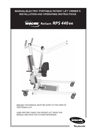
Reliant RPS 440 ee Owners Installation and Operating Manual
User Manual
26 Pages
Preview
Page 1
DEALER: THIS MANUAL MUST BE GIVEN TO THE USER OF THE PATIENT LIFT. USER: BEFORE USING THIS PATIENT LIFT, READ THIS MANUAL AND SAVE FOR FUTURE REFERENCE.
DO NOT OPERATE THIS EQUIPMENT WITHOUT FIRST READING AND UNDERSTANDING THE WARNINGS, CAUTIONS AND INSTRUCTIONS IN THIS MANUAL AND THE OWNER'S MANUAL PROVIDED WITH THE SLINGS. IF YOU ARE UNABLE TO UNDERSTAND THE WARNINGS, CAUTIONS, AND INSTRUCTIONS, CONTACT A HEALTHCARE PROFESSIONAL, DEALER OR TECHNICAL PERSONNEL IF APPLICABLE BEFORE ATTEMPTING TO USE THIS EQUIPMENT - OTHERWISE INJURY OR DAMAGE MAY RESULT. THE INFORMATION CONTAINED IN THIS DOCUMENT IS SUBJECT TO CHANGE WITHOUT NOTICE.
RADIO FREQUENCY INTERFERENCE Most electronic equipment is influenced by Radio Frequency Interference (RFI). CAUTION should be exercised with regard to the use of portable communication equip-ment in the area around such equipment. If RFI causes erratic behavior, PUSH the Red Emergency Stop Button IMMEDIATELY. DO NOT turn the Red Emergency Stop Button OFF while transmission is in progress. This product meets EN60601-1-2 Collateral Standard: Electromagnetic Compatibility. MAINTENANCE Maintenance MUST be performed ONLY by qualified personnel. WARNING notices as used in this manual apply to hazards or unsafe practices which could result in serious bodily harm. CAUTION notices as used in this manual apply to hazards or unsafe practices which could result in minor personal injury or property damage. NOTES highlight procedures and contain information which assist the operator in understanding the information contained in this manual. SAVE THESE INSTRUCTIONS AND KEEP WITH PATIENT LIFT AT ALL TIMES.
1
ALWAYS be aware of the Lift Arms. Injury to the patient and/or assistant may occur. ALWAYS be aware of the Footrest, especially the patient’s position on the footrest. Injury to the patient and/or assistant may occur.
Device contains Lead Acid Gel Cell batteries. DO NOT dispose of batteries in normal household waste. They MUST be taken to a proper disposal site. Contact your local waste management company for information.
S P E C I F I C A T I O N S
Height at Sling Hook-up MAXIMUM: Height at Sling Hook-up MINIMUM: Base Width OPEN: Base Width CLOSED: Base Height (Clearance): Base Length: Overall Height: Overall Length: Overall Width: Caster Size FRONT/REAR: Sling Options: Sling Material: Weight Capacity: Weight: Shipping Weight: Battery: Charger Input: Charger Output: Charging Time: Audio Low Battery Alarm: Motor Safety Devices: * Approx. Lifts per Charge: Warranty (Electric/Electronics): Emergency Stop Button:
67-inches / 1700 mm 39-inches / 990 mm 44-inches / 1120 mm 26-inches / 660 mm 5-inches / 125 mm 41.5-inches / 1054 mm 46-inches / 1170 mm 45-inches / 1145 mm 26.5-inches / 672 mm 4-inches / 100 mm Standing or Transport Polyester 440lbs. / 200 kg 116.5lbs. / 53 kg 167lbs. / 76 kg 24 VDC RECHARGEABLE 100 - 240 VAC 29.5 VDC Maximum 6 Hours YES Anti-Entrapment *100-200 Cycles per Charge 1 Year YES 2
TABLE OF CONTENTS . SPECIAL NOTES... 1 SPECIFICATIONS ... 2 SAFETY SUMMARY ... 4 ASSEMBLY... 6 OPERATION ... 10 OPERATING THE STAND UP LIFT ... 10 Locking/Unlocking the Rear Swivel Casters ... 10 Raising/Lowering Stand Up Lift ... 10 Closing/Opening the Legs of the Base ... 10 Mounting Battery Charger... 11 Charging the Batteries ... 12 TRANSFERRING FROM... 13 Lifting Preparation ... 13 Lifting the Patient ... 13 Moving the Patient ... 15 TRANSFERRING TO ... 16 Transferring the Patient to a Wheelchair ... 16 Transferring the Patient to a Bed ... 17 Transferring the Patient to a Commode ... 18 MAINTENANCE SAFETY INSPECTION CHECKLIST ... 19 TROUBLESHOOTING ... 20 CARE AND MAINTENANCE OF YOUR STAND UP LIFT ... 21 Lubrication ... 21 Wear And Damage... 21 Cleaning ... 22 Electric Actuator Replacement ... 22 Base Adjustment... 22 LIMITED WARRANTY ... 23 NOTES ... 24
3
T A B L E O F C O N T E N T S
S A F E T Y S U M M A R Y
SAFETY SUMMARY NOTE: Check all parts for shipping damage before using. In case of damage, DO NOT use the equipment. Contact the Carrier/Dealer for further instructions. NOTE: The stand up lift may be operated by one (1) healthcare professional for ALL lifting preparation, transferring from and transferring to procedures with a cooperative, weight--bearing individual able to support the majority of his/her own weight. However, since medical conditions vary, Invacare recommends that the healthcare professional evaluate the need for assistance and determine whether more than one (1) assistant is appropriate in each case to safely perform the transfer.
DO NOT attempt any transfer without approval of the patient’s physician, nurse or medical assistant. Thoroughly read the instructions in this Owner’s Manual, observe a trained team of experts perform the lifting procedures and then perform the entire lift procedure several times with proper supervision and a capable individual acting as a patient. Individuals that use the Standing Sling MUST be able to support the majority of their own weight, otherwise injury can occur. DO NOT raise the patient to a full standing position while using the transport sling otherwise injury can occur. Invacare standing and transport slings are specifically designed to be used in conjunction with the Invacare Stand Up Lift. Slings and accessories designed by other manufacturers or other Invacare slings are not to be utilized as a component of Invacare’s stand up lift system. Use of these products is prohibited and will void Invacare’s stand up lift warranty. Use only genuine Invacare standing and transport slings and lift accessories to maintain patient safety and product utility. Use the sling that is recommended by the individual’s doctor, nurse or medical assistant for the comfort and safety of the individual being lifted. Before positioning the legs of the stand up lift around the patient, make sure the patient's feet are out of the way of the footplate, otherwise injury can occur. Invacare recommends locking the rear swivel casters ONLY when positioning or removing the sling (standing or transport) from around the patient.
4
Invacare does NOT recommend locking the rear swivel casters of the stand up lift when lifting and transferring an individual. Doing so could cause the lift to tip and endanger the patient and assistants. Invacare DOES recommend that the rear swivel casters be left UNLOCKED during lifting and transferring procedures to allow the stand up lift to stabilize itself when the patient is initially lifted from and transferred to a chair, bed or any stationary object. STANDING SLINGS - DO NOT use the standing sling in combination with the stand up lift as a transport device. It is intended to transfer an individual from one resting surface to another (such as a bed to a wheelchair). Moving a person using the standing sling in combination with the stand up lift over ANY distance is NOT recommended. STANDING SLINGS - Before lifting the patient, make sure the bottom edge of the standing sling is positioned on the lower back of the patient and the patient's arms are outside the standing sling. STANDING SLINGS - The belt MUST be snug, but comfortable on the patient, otherwise the patient can slide out of the sling during transfer, possibly causing injury. TRANSPORT SLINGS - Before lifting the patient, make sure the bottom edge of the transport sling is at the base of the spine and the patient's arms are outside the transport sling. DO NOT use any kind of material (such as a plastic back incontinence pad or seating cushion) between the patient and sling material that may cause the patient to slide out of the sling during transferring. ALWAYS use the color coded strap on the standing sling closest to the patient while still maintaining patient stability and comfort. Bleached, torn, cut, frayed, or broken slings are unsafe and could result in injury. Discard Immediately. DO NOT alter slings. When elevated a few inches off the surface being transferred from and before moving the patient, check again to make sure that the sling is properly connected to the attachment points of the stand up lift. If any attachments are NOT properly in place, lower the patient back onto the surface and correct this problem.
5
S A F E T Y S U M M A R Y
S A F E T Y
During transfer, with patient suspended in a sling attached to the lift, DO NOT roll stand up lift over objects such as carpet, raised carpet bindings, door frames, or any uneven surfaces or obstacles that would create an imbalance of the stand up lift and could cause the stand up lift to tip over. Use push handle on the mast at ALL times to push or pull the stand up lift. Casters and axle bolts require inspection every six (6) months to check for tightness and wear.
S U M M A R Y
After the first 12 months of operation, inspect all pivot points and fasteners for wear. If the metal is worn, the parts MUST be replaced. Make this inspection every six (6) months thereafter. The electric motor is sealed at the factory and if service is required, the motor unit MUST BE returned to the factory for repair. DO NOT attempt to open the motor or obtain local service as this will VOID the warranty and may result in damage and a costly repair. Consult your Dealer or Invacare for further information. Regular maintenance of Stand Up Lift and accessories is necessary to assure proper operation. WEIGHT LIMITATION DO NOT exceed maximum weight limitation of the Stand Up Lift. The maximum weight limitation is 440 lbs. regardless of any additional weight limitations on accessories.
A S S E M B L Y
ASSEMBLY OF THE PATIENT LIFT The RPS400ee is packed partly assembled for shipping purposes. To assemble your RPS400ee, remove all contents from box and place unit on workbench or table. Using 16 mm and 17 mm spanners remove the two bolts connecting the mast to the chassis. Remove bolts.
6
Remove mast and boom assembly from base . Position upright and attach mast to base using the previously removed bolts.
A S S E M B L Y
Note: Ensure these bolts are firmly tightened. Attach the rod ends as shown in
.
When assembling the patient lift, it is important to tighten bolts according to instruction. Failure to do so may result in damage to the lift or injury to the care-giver or client. Cut cable tie securing actuator , and swing actuator forward so that it is out of the way. Swing boom up and over to the front
.
Attaching the push handle The push handle is attached to the back of the mast using the two screws provided.
Attaching the kneepad receiver Note: The kneepad is an integral part of the lift and must be attached so that the lifter can function correctly and safely. Remove the two hex screws on front of mast behind the actuator. Align the kneepad receiver assembly over the screw holes . Ensure the assembly is correctly orientated - the kneepad release lever should be on top. Replace the screws. Tighten firmly. 7
A S S E M B L Y
Using16 mm and 17 mm spanners, connect top of actuator to boom using bolt provided . Note: Do not over-tightening this bolt as this will deform the clevis and restrict the pivot.
The kneepad is fundamental to the safe standing of patients by this lift. With the exception of using this lift as a gait-trainer, the kneepad must be fitted to the lift.
Attaching the kneepad Attach the kneepad to the kneepad receiver by sliding the two posts into the tube retainers of the kneepad receiver assembly and at the same time turning the kneepad release lever in a clockwise direction. Release the lever and slide the kneepad in or out until the mechanism engages and locks the kneepad.
Attaching the battery Fit battery to control box. For more information about this procedure refer to page 12 of this manual.
push
8
Ensure control box emergency push button is set to the off position (out). If not, twist the button one quarter of a turn clockwise and the button will pop out.
Emergency push button
To mount battery charger on wall, refer to page 11: Mounting Battery Charger in this manual.
9
A S S E M B L Y
O P E R A T I O N
OPERATING THE STAND UP LIFT Locking/Unlocking the Rear Swivel Casters Perform one (1) of the following: LOCKING - Press DOWN on the BOTTOM of the locking lever. UNLOCKING - Press DOWN on the TOP of the locking lever. UP
DOWN
Raising/Lowering Stand Up Lift RAISING THE LIFT Press the UP button on the hand control to raise the lift arms and the patient.
OPEN
CLOSE
LOWERING THE LIFT Press the DOWN button on the hand control to lower the lift arms and the patient. NOTE: If the Stand Up Lift is in the full UP position, it may be necessary to pull down slightly on the lift arms before the mast will lower. EMERGENCY STOP. Press the RED button on the control box IN to stop the lift arms and patient from raising or lowering. (Refer to page 9).
EMERGENCY STOP
NOTE: Rotate RED emergency stop button CLOCKWISE until it pops out to disengage. EMERGENCY LOWERING. In the event of a handset or control box failure, the lifter can still be lowered by the following methods: 1/ By pressing the tip of a ballpoint pen into the small circle below and to the right of the stop button on the control box. 2/ By pulling up the red tag on the actuator column (actuator must be loaded).
Closing/Opening the Leg Base The bottom row of the handset is used to open or close the legs of the base for stability prior to lifting a patient. Pressing the left button widens the leg base; the right button closes the leg base. 10
EMERGENCY LOWER 1 (use ballpoint pen)
EMERGENCY LOWER 2 (raise red tag)
Mounting Battery Charger NOTE: Refer to your local regulations concerning proper mounting procedures. 1. Place the battery charger with mounting bracket on the wall at the desired position. 2. With a pencil, mark the MIDDLE hole position. 3. Measure down 6-1/2-inches (165mm) from the pencil mark and drill one (1) mounting hole. 4. Install the BOTTOM mounting screw until there is an approximate1/8inch (3mm) gap between the screw head and the wall. 5. Install the battery charger with mounting bracket onto the bottom mounting screw. 6. Drill the remaining two (2) mounting holes. 7. Install the two (2) remaining mounting screws through the mounting bracket and into the wall. Tighten securely. 8. Plug the battery charger into the wall electrical outlet. NOTE: ON LED should illuminate.
11
O P E R A T I O N
O P E R A T I O N
Charging the Batteries NOTE: Invacare recommends the battery be recharged daily to prolong battery life. NOTE: An audible alarm will sound (beep) when battery is low. 1. Lift UP on the handle on the back of the battery. 2. Lift the battery UP and OUT away from the control box.
Make sure there is an audible click when mounting battery either on the battery charger or control box to confirm proper mounting. Otherwise, injury or damage may occur. Refer to diagram below for correct 3. Place the battery on the battery charger as shown in the following diagram. Make sure there is an audible click. NOTE: The charge LED will illuminate. When charging is complete, charge LED will stop illuminating. NOTE: A battery needing to be fully recharged will take approximately four (4) hours. 4. Lift UP on the handle on the back of the battery. 5. Lift the battery UP and OUT away from the battery charger. 6. Reinstall the battery onto the control box as shown. Make sure there is an audible click.
12
TRANSFERRING FROM Lifting Preparation NOTE: The stand up lift may be operated by one (1) healthcare professional for ALL lifting preparation, transferring from and transferring to procedures with a coop-erative, weight-bearing individual able to support the majority of his/her own weight. However, since medical conditions vary, Invacare recommends that the healthcare professional evaluate the need for assistance and deter-mine whether more than one (1) assistant is appropriate in each case to safely perform the transfer.
STANDING SLINGS - Before lifting the patient, make sure the bottom edge of the standing sling is positioned on the lower back of the patient and the patient's arms are outside the standing sling. TRANSPORT SLINGS - Before lifting the patient, make sure the bottom edge of the transport sling is at the base of the spine and the patient's arms are outside the transport sling. Invacare does NOT recommend locking the rear casters of the stand up lift when lifting and transferring an individual. Doing so could cause the lift to tip and endanger the patient and assistants. Invacare DOES recommend that the rear casters be left UNLOCKED during lifting and transferring procedures to allow the stand up lift to stabilize itself when the patient is initially lifted from and transferred to a chair, bed or any stationary object.
Lifting the Patient 1. Instruct the patient to do the following: A. Hold onto the hand grips on both sides of the stand up lift. B. Lean back into the standing or transport sling.
13
T R A N S F E R R I N G F R O M
T R A N S F E R R I N G F R O M
2. Make sure of the following: A. Patient's knees are secure against the knee pad. B. Patient's feet are positioned on the footplate. C. The bottom edge of the: Standing Sling is positioned on the lower back. Transport Sling is at the base of the patient's spine. D. The patient's arms are outside of the standing or transport sling. E. The rear casters are unlocked. F. Make sure the legs are in the maximum open position.
When elevated slightly off the surface being transferred from and before moving the patient, check again to make sure that the sling is properly connected to the attachment points of the stand up lift. If any attachments are NOT properly in place, lower the patient back onto the surface and correct this problem. Adjustments for safety and comfort should be made before moving the patient. Invacare standing and transport slings are specifically designed to be used in conjunction with the Invacare Stand Up Lift. Slings and accessories designed by other manufacturers or other Invacare slings are not to be utilized as a component of Invacare’s stand up lift system. Use of these products is prohibited and will void Invacare’s stand up lift warranty. Use only genuine Invacare standing and transport slings and lift accessories to maintain patient safety and product utility. If transferring from a wheelchair: Wheelchair wheel locks MUST be in the locked position BEFORE lowering the patient into the wheelchair. 3. Transferring from a wheelchair - Lock the wheel locks of the wheelchair. 4. Press the UP button to raise the patient above the surface (bed, wheelchair or commode) being transferred from. The patient should be elevated just high enough to clear the surface with their weight fully supported by the lift. NOTE: The lower center of gravity provides stability making the patient feel more secure and the lift easier to move. 14
NOTE: Lift arms will stay in position until the DOWN button is pressed. 5. Move the patient to the desired surface. Refer to Moving the Patient in this section of the manual.
Moving the Patient
STANDING SLINGS - DO NOT use the standing sling in combination with the stand up lift as a transport device. It is intended to transfer an individual from one resting surface to another (such as a bed to a wheelchair). Moving a person using the standing sling in combination with the stand up lift over ANY distance is NOT recommended. During transfer, with patient suspended in a sling attached to the lift, DO NOT roll stand up lift over objects such as carpet, raised carpet bindings, door frames, or any uneven surfaces or obstacles that would create an imbalance of the stand up lift and could cause the stand up lift to tip over. Use push handle on the mast at ALL times to push or pull the stand up lift.
1. Using the push handle, move the stand up lift away from the surface. 2. SLOWLY, move the patient to the desired surface. 3. Lower the patient onto the desired surface. Refer to TRANSFERRING TO in this manual.
15
T R A N S F E R R I N G F R O M
T R A N S F E R R I N G T O
TRANSFERRING TO NOTE: The stand up lift may be operated by one (1) healthcare professional for ALL lifting preparation, transferring from and transferring to procedures with a cooperative, weight-bearing individual able to support the majority of his/her own weight. However, since medical conditions vary, Invacare recommends that the healthcare professional evaluate the need for assistance and determine whether more than one (1) assistant is appropriate in each case to safely perform the transfer.
Transferring the Patient to a Wheelchair 1. Move the wheelchair into position.
Wheelchair wheel locks MUST be in the locked position BEFORE lowering the patient into the wheelchair. 2. Lock the rear wheels of the wheelchair. 3. Position the patient over the wheelchair. 4. Press the DOWN button and lower the patient into the wheelchair.
Invacare recommends locking the rear swivel casters ONLY when positioning or removing the sling (standing or transport) from around the patient. 5. Lock the rear swivel casters. Refer to LOCKING/UNLOCKING THE REAR SWIVEL CASTERS in the OPERATION section of this manual. 6. Unhook the standing or transport sling from all attachment points on the stand up lift. 7. If equipped, unfasten the leg strap from around the patient's legs. 8. Instruct the patient to lift their feet off of the footplate. NOTE: Assist the patient if necessary. 9. Remove the standing or transport sling from around the patient. 10. Pull the stand up lift away from the wheelchair. 16
Transferring the Patient to a Bed NOTE: The lower center of gravity provides stability making the patient feel more secure and the lift easier to move. NOTE: The lift arms will stay in position until the DOWN button is pressed. 1. Position the patient as far over the bed as possible. NOTE: If patient is being transferred from a surface that is lower than the bed, press the UP button to raise the patient above the surface of the bed. The patient should be elevated just high enough to clear the bed with their weight fully supported by the lift. 2. Press the DOWN button and lower the patient onto the bed.
Invacare recommends locking the rear swivel casters ONLY when positioning or removing the sling (standing or transport) from around the patient.
3. Lock the rear swivel casters. Refer to Locking/Unlocking the Rear Swivel Casters in the OPERATION section of this manual. 4. Unhook the standing or transport sling from all attachment points on the stand up lift. 5. If equipped, unfasten the leg strap from around the patient's legs. 6. Instruct the patient to lift their feet off of the footplate. NOTE: Assist the patient if necessary. 7. Remove the standing or transport sling from around the patient. 8. Pull the stand up lift away from the bed.
17
T R A N S F E R R I N G T O
T R A N S F E R R I N G T O
Transferring the Patient to a Commode 1. Position the patient over the commode. 2. Press the DOWN button and lower the patient onto the commode.
Invacare recommends locking the rear swivel casters ONLY when positioning or removing the sling (standing or transport) from around the patient. 3. Lock the rear swivel casters. Refer to Locking/Unlocking the Rear Swivel Casters in the OPERATION section of this manual. 4. Perform one (1) of the following: A. Standing Sling Unhook the standing sling from the attachment points on the stand up lift. B. Transport Slings Unhook the transport sling from the bottom attachment points on the stand up lift. Lift up on the patient's legs and remove the thigh supports from underneath the patient. If desired, unhook the transport sling from the top attachment points on the stand up lift. NOTE: The patient can remain in the upper portion of the transport sling while using the commode. 5. If equipped, unfasten the leg strap from around the patient's legs. 6. Instruct the patient to lift their feet off of the footplate. NOTE: Assist the patient if necessary. 7. Remove the standing or transport sling from around the patient. 8. Pull the stand up lift away from the commode. 9. Once the patient is ready to be transferred, refer to the LIFTING PREPARATION section of this manual. 18
MAINTENANCE SAFETY INSPECTION CHECKLIST
THE CASTER BASE Inspect for missing hardware. Base opens/closes with ease. Inspect casters and axle bolts for tightness. Inspect casters for smooth swivel and roll.
X X X X
X X X X
X X X X
THE MAST Mast MUST be securely assembled to boom. Inspect for bends or deflections.
X X
X X
X X
X X X
X X X
X X X
X
X
X
X
X
X
X
X
X
CLEANING Whenever necessary.
X
X
X
SLINGS CHECK ALL SLING ATTACHMENTS each time it is used to ensure proper connection and patient safety. Inspect sling material for wear. Inspect straps for wear.
X X X
X X X
X X X
THE LIFT ARMS AND LINKAGE Check all hardware and attachment points. Inspect for bends or deflections. Inspect bolted joints of lift arms for wear. Inspect to ensure that the lift arms are centered between the base legs. ELECTRIC ACTUATOR ASSEMBLY Check for wear or deterioration. (IF DAMAGED, CONTACT DEALER). Cycle to ensure smooth quiet operation.
NOTE: For individual home use, a full inspection is required prior to each new user. NOTE: Regular cleaning will reveal loose or worn parts, enhance smooth operation and extend the life expectancy of the lift.
19
I N S P E C T I O N C H E C K L I S T