Maintenance Manual
76 Pages
Preview
Page 1
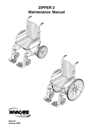
ZIPPER
Contents Chapter 1
Page
Introduction Introduction ... 1.3 Policy ... 1.5 Technical Details ... 1.5 Types ... 1.5
Chapter 2
Maintenance Scope ... 2.3 Inspection ... 2.3 Tools ... 2.4 Removing And Replacing The Backrest Canvas And Push Handle ... 2.7 Removing And Replacing An Armrest Assembly ... 2.11 Removing And Replacing Transit Rear Wheel Assemblies... 2.15 Removing And Replacing Transit Rear Wheel Kits (Standard And Amputee Kits) ... 2.17 Removing And Replacing Self Propelling Rear Wheel Assemblies ... 2.19 Removing And Replacing Wheel Mounting Bush (Standard - QR Hub) ... 2.23 Removing And Replacing Self Propelling Wheel Mounting Block ... 2.25 Removing And Replacing A Brake Assembly ... 2.27 Removing And Replacing A Castor Assembly ... 2.29 Removing And Replacing A Swing/Detachable Footrest Assembly ... 2.31 Removing And Replacing A Seat Canvas ... 2.33 Removing And Replacing A Backrest Extension... 2.35 Removing And Replacing A Self Propelled Amputee Kit ... 2.37 Removing And Replacing A Safety Buckle Belt ... 2.39 Removing And Replacing A Spokeguard Kit ... 2.41 Removing And Replacing A Capstan Handrim Kit ... 2.43 Removing And Replacing A Anti Tipping Lever and Tipping Lever ... 2.45 Removing An Adjusto Tray - Full Armrest and Desk Armrest ... 2.47 Removing And Replacing Cross Bar Assembly ... 2.49 Removing And Replacing Seat Adjustment Tube Kit ... 2.51 Removing And Replacing Cross Bar Pivot Support Kit ... 2.53 Removing And Replacing Cross Bar Pivot Bolt Kit ... 2.55 Removing And Replacing Cross Bar Link Kit ... 2.57 Removing And Replacing Side Frame Kit ... 2.59 Removing And Replacing Rear Socket Assembly ... 2.61 Removing And Replacing Front and Rear Seat Support Kit ... 2.63 Removing And Replacing Side Frame Tube Plug Kit ... 2.65 Removing And Replacing Footrest Catch Bolt Kit ... 2.67 Removing And Replacing Cross Bar Pivot Stop Kit ... 2.69
Prelims ii
01/00
INTRODUCTION
Chapter 1 Introduction
01/00
Page 1.1
INTRODUCTION
Introduction 1 This manual provides basic details to enable the ZIPPER 2 Wheelchair to be maintained. It is not intended to be a comprehensive maintenance guide/policy, but is intended for use by competent personnel to enable the chair to be adequately maintained. 2 The manual has the following chapters: Chapter 2
Detailing assemblies that are maintainable and the relevant procedures.
3 The Zipper 2 Wheelchair is manufactured by: INVACARE U.K. Ltd South Road Bridgend Industrial Estate Bridgend Mid-Glamorgan CF31 3PY Tel No: 01656 647327 Fax No: 01656 649016 4 For Customer Service enquires, repairs, servicing and spares, contact INVACARE U.K. Ltd at the address above and quote all the details as indicated in paragraphs 5 and 6. 5 Quote the following details at all times: 5.1 Part Number 5.2 Description 5.3 Quantity required 6 For certain orders the following should also be quoted: 6.1 Serial or batch number 6.2 End user
01/00
Page 1.3
ZIPPER 2
Policy 8 INVACARE Ltd repair policy is as follows:
Repairs to ANY component other than those detailed in Chapter 2 are not covered. Repairs to ANY metal work is not generally permitted without express permission of INVACARE Ltd. ALL fasteners i.e. bolts, Nyloc nuts, and any fastener showing damage MUST be renewed. Failure to comply with the above absolves INVACARE Ltd of liability.
☞ Note: Certain components will require removal to carry out maintenance. With the exception of fasteners, these components should be refitted.
Technical Details 9 The following data applies to the Zipper 2. 9.1 Available seat widths: 13 inches to 18 inches. 9.2 Chair depth available (adjusted using telescopic tube): 15 inches to 18 inches. 9.3 Seat to ground height: 17 1/2 inches and 19 inches. 9.4 Wheel types available: 12 1/2 in transit with pneumatic or solid tyre. 20 in with pneumatic tyre. 22 in and 24 in with pneumatic or solid tyre. Located in mounting blocks bolted to frame. Option for Quick Release (Q.R.) hub is available for all self propelling wheels. 9.5 Maximum user weight: 115 kg (18 stone). 9.6 Backrest type: 7 1/2° bend, angled backrest. 9.7 Chair finish: Polyester powdered coat (colour as required). 9.8 Weight of chair: 13.5 kg to 14.4 kg dependant on configuration.
Types Options 10 The chair is available in various user defined optional types. For further details refer to INVACARE UK Ltd for details and acceptable combinations. The weight of the chair may increase with options.
Page 1.4
01/00
MAINTENANCE
Chapter 2 Maintenance
01/00
Page 2.1
MAINTENANCE
Scope 1 This chapter details the removal and/or replacement procedures required for the following assemblies and/or items. It is not intended to be a strict policy of maintenance but should be used as a guide only. 2 The assemblies covered (refer to Fig 2.0) are as follows: Section
Assembly
Page
2.1 Removing And Replacing The Backrest Canvas And Push Handle 2.7 2.2 Removing And Replacing An Armrest Assembly 2.11 2.3 Removing And Replacing Transit Rear Wheel Assemblies 2.15 2.4 Removing And Replacing Transit Rear Wheel Kits (Standard And Amputee Kits) 2.17 2.5 Removing And Replacing Self Propelling Rear Wheel Assemblies 2.19 2.6 Removing And Replacing Wheel Mounting Bush (Standard - QR Hub) 2.23 2.7 Removing And Replacing Self Propelling Wheel Mounting Block 2.25 2.8 Removing And Replacing A Brake Assembly 2.27 2.9 Removing And Replacing A Castor Assembly 2.29 2.10 Removing And Replacing A Swing/Detachable Footrest Assembly 2.31 2.11 Removing And Replacing A Seat Canvas 2.33 2.12 Removing And Replacing A Backrest Extension 2.35 2.13 Removing And Replacing A Self Propelled Amputee Kit 2.37 2.14 Removing And Replacing A Safety Buckle Belt 2.39 2.15 Removing And Replacing A Spokeguard Kit 2.41 2.16 Removing And Replacing A Capstan Handrim Kit 2.43 2.17 Removing And Replacing A Anti Tipping Lever and Tipping Lever 2.45 2.18 Removing An Adjusto Tray - Full Armrest and Desk Armrest 2.47 2.19 Removing And Replacing Cross Bar Assembly 2.49 2.20 Removing And Replacing Seat Adjustment Tube Kit 2.51 2.21 Removing And Replacing Cross Bar Pivot Support Kit 2.53 2.22 Removing And Replacing Cross Bar Pivot Bolt Kit 2.55 2.23 Removing And Replacing Cross Bar Link Kit 2.57 2.24 Removing And Replacing Side Frame Kit 2.59 2.25 Removing And Replacing Rear Socket Assembly 2.61 2.26 Removing And Replacing Front and Rear Seat Support Kit 2.63 2.27 Removing And Replacing Side Frame Tube Plug Kit 2.65 2.28 Removing And Replacing Footrest Catch Bolt Kit 2.67 2.29 Removing And Replacing Cross Bar Pivot Stop Kit 2.69 3 For the tools required refer to the list of tools detailed in paragraph 12. Any special tooling and/or torque requirements will be referred to within the relevant text. 4 General engineering practices and safe working practices must be adhered to at all times.
01/00
Page 2.3
ZIPPER 2
CHAPTER 2.0
5 For further information on the assemblies contained within this chapter, contact Customer Services, INVACARE UK Ltd., (refer to address in chapter 1) quoting the following details: 5.1 Part Number 5.2 Description 5.3 Quantity required 6 For certain orders the following should also be quoted: 6.1 Serial or batch number 6.2 End user 7 For any ordering or spares procurement, contact INVACARE U.K. Ltd., (refer to address in Chapter 1) quoting the details in paragraphs 5 and 6.
Inspection 8 In general, a weekly visual check will meet all the inspection requirements. 9 Ensure that the following are checked: 9.1 Fabric is undamaged and has no signs of sagging. 9.2 The footrest is correctly fitted and latched. 9.3 Both armrests are securely fitted in place. 9.4 Brake mechanism operates freely and when locked, the chair does not move. 9.5 Footplates and heel slings are undamaged and are correctly fitted. 9.6 Tyres are in good order and the wheels are not damaged. 9.7 If stabilisers are fitted, they are firmly locked in place.
10 Check the finish of the chair for any damage.
☞ Note: Some finishes are unique to the chair. Check with INVACARE UK Ltd for details.
11 Check that all bungs and hand grips are fitted and undamaged.
Tools 12 The following list details the basic tools required to carry out the maintenance given in the following sub-chapters.
Page 2.4
12.1
Pliers
12.2
Drills (Metric and Imperial)
12.3
Spanners (Metric and Imperial)
12.4
Pozi drive screwdriver
12.5
Thin flat bladed screwdriver
12.6
Adjustable spanner
01/00
MAINTENANCE
12.7
Torque wrench (20 to 40 lbf.ft rating)
12.8
Set of Allen keys (Metric and Imperial)
12.9
Protected jaw grips
12.10 Nylon mallet 12.11 Pop rivet gun 12.12 Thin nosed pliers 12.13 Electric hand drill 12.14 Bradawl
☞ Note: The above list is not exhaustive.
01/00
Page 2.5
ZIPPER 2
1 2 3 4 5 6 7
Backrest canvas Hand grips Push handle LH Upholstery washer Pozi drive head screw Backrest lever Button head bolt
8 9 10 11 12 13 14
Nyloc nut Plain washer Backrest pin Backrest pin spring Nyloc nut Plain washer Lower backrest frame
Figure 2.1 Backrest Assembly
Page 2.6
01/00
MAINTENANCE
2.1
Removing And Replacing The Backrest Canvas And Push Handle
General 1 Check the backrest canvas (1) and push handle (3) for any defects, (refer to paragraphs 4 and 5). If any defects are observed then refer to paragraphs 6 to 7 for maintenance details and to Spares Catalogue for parts information. 2 Ensure that the push handle locks securely into place and that the locking mechanism functions correctly. Tools 3 Refer to the tool list at the beginning of this Chapter. Inspection 4 Inspect on a weekly basis for the following: 4.1 No signs of sagging, stretching or excessive wear in the canvas (1). 4.2 No evidence of fraying, especially around the fastener points. 4.3 Pozi drive head screws (5) not missing. 4.4 Cup washers (4) not missing. 5 Inspect the locking mechanism for the following: 5.1 Levers are not deformed or damaged. 5.2 Locks safely when the push handle (3) is in the upright position. 5.3 Not excessively stiff to operate (action should be smooth and positive). Removal of the backrest canvas and push handle assembly 6 To remove or replace the backrest canvas (1) proceed as follows: 6.1 Release the locking levers (6) and fold the push handle (3) down. 6.2 Unscrew and remove the four pozi drive head screws (5) and cup washers (4). 6.3 Unscrew and remove the two button hd bolts (7), Nyloc nuts (8) and plain washers (9). 6.4 Unscrew and remove the two backrest pins (10), springs (11), backrest lever (6), Nyloc nuts (12) and plain washers (13). 6.5 Slide the backrest canvas (1) off the push handle (3). 6.6 Slide the backrest canvas (1) off the lower half of the back frame (14). Replacing the backrest canvas and push handle assembly 7 To replace the backrest canvas is the reverse of the removal, however ensure the following:
01/00
7.1
New nyloc nuts are fitted.
7.2
The securing points are undamaged.
7.3
New cup washers are fitted as required.
7.4
That the backrest canvas is stretched evenly and is taut.
Page 2.7
ZIPPER 2
2
1
4
3
4
1 2 3 4
Handle assembly Black hand grip Hinge casting kit Pop rivet
Figure 2.2 Handle Tube Assembly
Page 2.8
01/00
MAINTENANCE
Removal of snap in bottom casting kit 8 To remove the snap in bottom casting kit proceed as follows: 8.1
Ensure that armrest is removed (Section 2.2). Support the wheelchair as stable as possible. CAUTION:
8.2
Ensure that when drilling out the rivets (4) the holes in the frame are not damaged.
Using a 5 mm Ø drill bit, drill out the four rivets (4) and remove casting.
Replacing snap in bottom casting kit 9 To replace the snap in bottom casting kit proceed as follows: 9.1
Ensure that the casting is located correctly and secure. Use pop rivets supplied.
Removal of hand grip 10 To remove the hand grip proceed as follows: 10.1 Remove push handle assembly (Paragraph 6). Support the push handle in a soft jawed vice. CAUTION:
Great care must be taken when using sharp instruments.
10.2 Carefully cut the hand grip along its length, using a sharp implement. The hand grip can then be removed. Replacement of hand grip 11 To replace the hand grip proceed as follows: 11.1 Apply 3 drops of instant glue inside the mouth of the hand grip. 11.2 Align hand grip onto push handle and fully locate hand grip onto push handle using a nylon mallet.
01/00
Page 2.9
ZIPPER 2
1
2
8
8
1
3 7 2
6
4
5
Full Armrest 8
4
3 7
6
5
Desk Armrest 1 2 3 4
Armrest pad Armrest frame Armrest panel Pop rivet
5 6 7 8
Bung Release lever Armlock pin Pozi drive head screw
Figure 2.3 Armrest Assembly
Page 2.10
01/00
MAINTENANCE
2.2
Removing And Replacing An Armrest Assembly
General
☞ Note: The armrest assembly comprises the following:
The armrest (1), armrest panel (3) and a frame (2) and locking mechanism (6,7).
1 Check the armrest (1) and frame (2) for any defects (refer to paragraph 4). If any defects are observed then refer to paragraphs 5 to 8 for maintenance details and to Spares Catalogue for parts information. 2 The armrest can be renewed as either: 2.1
A complete assembly.
2.2
Arm release and plug kit.
2.3
Armpad kit
2.4
3/4 in Tube end plug (Desk arm only)
Tools 3 Refer to the tool list at the beginning of this Chapter. Inspection 4 Inspect on a weekly basis for the following: 4.1
Frame (2), armrest panel (3) and finish are undamaged.
4.2
Armpad (1) is undamaged and securely fastened in place.
4.3
Locking mechanism functions properly.
Repairing An Armrest Assembly
☞ Note: For ease of maintenance the armrest assembly can be replaced as a complete assembly.
5 To repair the armrest assembly proceed as follows: 5.1
Support the frame (2) using a soft jawed vice.
6 Removing the armrest pad kit. 6.1
Unscrew and remove the two pozi drive screws (8).
6.2
Remove the armrest pad kit from the frame.
7 Remove arm release and plug kit (5, 6 and 7).
01/00
7.1
Support armrest using a soft jawed vice.
7.2
Using a flat edged screw driver prise out end plug (5).
7.3
With release lever (6) in the open position, slide lever upwards releasing it from spring clip (7). Depress spring clip into tube using a small screw driver. Push spring clip outwards from frame. Spring clip may be removed using thin nosed pliers
7.4
Slide release lever (6) from armrest frame (2).
Page 2.11
ZIPPER 2
1
12
9 11 2
8
10
4
3
7
6
5
1 2 3 4 5 6
Armrest pad Armrest frame Armrest panel Briv rivet Bung Release lever
7 8 9 10 11 12
Armlock pin Pozi drive head screw Upper arm tube assembly Hand knob Bung Spring clip button
Figure 2.4 Adjustable Height Armrest Assembly
Page 2.12
01/00
MAINTENANCE
Replacing Armrest Components 8 To replace any of the components of the armrest is the reverse of the removal; however ensure the following: 8.1 Bungs (5) are undamaged when replaced. 8.2 Release mechanism operates freely 9 Removal of adjustable height armrest pad kit. 9.1
See paragraph 6.
10 Removal of upper arm assembly 10.1 Loosen hand knob (10). 10.2 Depress spring clip button (12) and remove upper arm assembly from armrest frame. 11 Removal of arm release and plug kit 11.1 See paragraph 7. 12 To replace any of adjustable height armrest components is the reverse of removal; however ensure the following: 12.1 Bungs (5) are undamaged when replaced. 12.2 Release mechanism works correctly. 12.3 Upper arm assembly can be adjusted in height correctly.
01/00
Page 2.13
ZIPPER 2
1
2
1 Wheel assembly
2
Locknut
Figure 2.5 Transit Rear Wheel Assembly
Page 2.14
01/00
MAINTENANCE
2.3
Removing And Replacing Transit Rear Wheel Assemblies
General
☞ Note: A transit type chair is fitted with 315 mm pneumatic or solid tyred wheels. 1 Check the wheel assembly for any defects (refer to paragraph 4). If any defects are observed then refer to paragraphs 5 and 6 for maintenance details and to Spares Catalogue for parts. 2 The main wheel assembly can be renewed as: 2.1
A complete assembly.
2.2
Pneumatic tyre.
2.3
Inner tube.
Tools 3 Refer to the tool list at the beginning of this Chapter. 3.1
A torque wrench of 25 lbf.ft rating is required.
Inspection 4 Inspect on a weekly basis for the following: 4.1
Damage to either wheel or tyre.
4.2
When the wheel assembly is allowed to free wheel that no binding, grating noise or unconcentric rotation are present.
4.3
Wheel rim and spokes are undamaged.
Removing A Transit Wheel Assembly 5 To remove a transit wheel (1) (refer to Fig 2.3) proceed as follows: 5.1
Raise and support the chair so the damaged wheel is free of the ground.
5.2
Using a suitable size spanner grip the nut located behind the wheel hub.
5.3
Using the torque wrench, unscrew and remove the locknut (2).
5.4
Slide the wheel free from its location on the frame.
6 Replacing a transit rear wheel assembly. CAUTION:
01/00
Apply Loctite 242 to the thread of the wheel shaft and ensure that the transit wheel locknut is tightened to a torque of 25 lbf.ft.
6.1
Replacing the transit rear wheel assemblies is the reverse of the removal.
6.2
Ensure brake assembly fully locks and that the chair is unable to move.
Page 2.15
ZIPPER 2
4
2
5
1 3 1
1 Dome head screws 2 Steel washers 3 Plastic coved washers
4 5
Side frame rear Transit rear wheel kit
Figure 2.6 Transit Rear Wheel Kit Assembly
Page 2.16
01/00
MAINTENANCE
2.4
Removing And Replacing Transit Rear Wheel Kits (Standard And Amputee Kits)
General
☞ Note: Ensure that if both assemblies are removed, the correct assembly is fitted to the correct side.
1 Check the transit rear wheel kit for any defects (refer to paragraph 3). If any defects are observed then refer to paragraphs 4 and 5 for maintenance details and to Spares Catalogue for parts. Tools 2 Refer to the tool list at the beginning of this Chapter. Inspection 3 Check the following: 3.1
Transit kit undamaged and securely fitted in place.
3.2
Locating holes are free from damage.
3.3
Nut and bolt are not missing.
Removing A Transit Rear Wheel Kit 4 To remove the transit rear wheel kit proceed as follows: 4.1
Unscrew and remove two dome head screws (1) and washers (2).
4.2
Unscrew and remove one dome head screw (1), two plastic coved washers (3) and steel washers (2).
4.3
Remove the transit rear wheel kit (5) from side frame rear (4).
Replacing transit rear wheel assembly. 5 Replacing the transit rear wheel kit is the reverse of the removal. 5.1
Ensure brake assembly fully locks and that the chair is unable to move.
☞ Note: To fit rear transit wheel, refer to section 2.3.
01/00
Page 2.17