User Manual
143 Pages
Preview
Page 1
C1 10/10/03 Rev 0
SECTION 1 page 1 of 1
FOUR CHANNEL CFAM4 Introduction The function of the CFAM4 is to obtain long-term recordings of the EEG on up to four channels, with a display of the EEG and a compressed display of variations of amplitude and frequency distributions. Additionally, if fitted with the appropriate software, it can record averaged evoked potentials from stimuli applied to the patient by external stimulators, triggered by the CFAM4. It is the fifth in a series of brain monitors (class IIb) which began with the Cerebral Function Monitor (CFM) in 1967 and have generated considerable clinical and research experience in the use of this type of equipment. A list of publications can be found on www.cfams.com. The CFAM4 is controlled almost entirely by four touch-screen arrow keys set to the top right of the screen. These actuate choices on two types of menus. The first type is a list which appears in a box on the screen. The up and down arrows enable you to move up and down the list. You can then select an item by pressing the right arrow. The second type of menu appears during recording and is a row of simulated buttons across the top of the screen. You can move from button to button across the screen by pressing the left and right arrow keys. The active button is highlighted.. To operate the buttons you use the up and down arrow keys. In routine clinical practice there is little use of these keys. The basic functions that they select are as follows:
1) Chart paper load-start (6 or 30cm.hour)-feed-stop. 2) Print out on the chart an unprocessed EEG sample. 3) Event marker on-off. 4) Adjust size of unprocessed electroencephalogram (EEG) displayed on the screen. 5) Alter the calibration signal at calibration socket on the rear right hand side of the CFAM4. This is where the headbox is normally stowed for transport.
The display format of CFAM4is virtually identical with that of the earlier CFAMs so that people with experience with the earlier instruments do not need retraining. Scientific publications with the earlier instruments remain applicable to CFAM4
BEFORE PROCEEDING WITH USE please read the section on EQUIPMENT CLASSIFICATION, WARNINGS AND NOTES. CFAM is a Registered Trademark of RDM Consultants Ltd. EQUIPMENT CLASSIFICATION The CFAMTM4 brain monitor is a Class IIb instrument designed for continuous use with skin surface, non-invasive electrodes, and with sub-dermal disposable needle electrodes, although the latter are not recommended (see warning
C1 10/10/03 Rev 0
SECTION 1 page 2 of 2
in section C4). Although it may be used as a vital signs monitor for adequacy of brain perfusion /auto-regulation during surgery it contains no alarms and interpretation of the display is subjective. Component lists, circuit diagrams and descriptions, test and calibration procedures, test software are provided / described in this manual. Servicing should only be undertaken by qualified personnel. >The CFAMTM4 has been tested to and complies with the following standards: >EN60601-1 (1990) Electrical safety. Medical Electronic Equipment. >EN60601-1-1 (2001) Collateral Standard, safety. >EN60601-1-2 (2002) EMC. 0120
CE Mark This denotes that RDM Consultants Ltd. is registered with SGS Yarsley International Certification Services Ltd. Year and month of manufacture.
1998-06
SN: xxxxxxxx
Batch and serial number assigned to a unit at the time of assembly. This symbol is attached to the head-box which contains a patient isolation amplifier. It indicates a type BF applied part.
This symbol is power OFF on the mains switch, when pressed in.
This symbol is power ON on the mains switch, when pressed in. This symbol means consult accompanying documents ( for further explanation.)
C1 10/10/03 Rev 0
SECTION 1 page 3 of 3
Equipotentiality connector
Indicates that circuits joined to a connector may be damaged by discharges of static electricity. Precautions should be taken to avoid touching contacts and to ground cable screens to the CFAM4 before attaching the cables. This symbol indicates that the connector outputs a signal
This symbol indicates that the connector is for an input signal This pulse symbol indicates that the CFAM4 AEP sweep can be triggered by either a +ve or a -ve going edge from an external +5 volt pulse source, or that it can issue similar triggers to an external stimulator. The polarity of the pulse is set by software menus in the CFAM4.
5v
WARNINGS REAR /TOP PANEL The CFAM4 will be supplied either for 230 volts 50Hz or 115 volts 60Hz mains supply Mains fuses, 230 volts: only use a 0.63 amp anti-surge type T (eg Littelfuse type 218, T,LBC). Mains fuses, 115 volts: only use a 1.25 amp anti-surge type T. See Appendix 2B4 for details of changing supply voltage.
!
WARNING, FOR CONTINUED PROTECTION AGAINST FIRE HAZARD REPLACE FUSES ONLY WITH SAME RATING AND TYPE
Replacement by a higher current fuse may, in the event of a fault, cause wire insulation or other items to ignite.
!
WARNING, OVERHEATING DO NOT OBSTRUCT FAN OUTLETS OR VENTILATION HOLES
Do not obstruct the fan inlets and outlets. Normally the rise in air temperature within the cabinet is no more than about 10 degrees Celsius above the ambient temperature. However obstructing the inlet or outlet fans may cause far higher temperatures to be reached. At best this may cause inaccuracies in analogue circuitry or temporary failure of digital circuits. At worst the overheating may lead to fire.
!
WARNING. EXPLOSION HAZARD. DO NOT USE IN THE PRESENCE OF FLAMMABLE VAPOURS
Some components, particularly the inrush limiting thermistor, several in the PSU and processor chips may run at high enough temperatures to ignite some gases. In fault conditions sparks may occur, particularly prior to fuse blowing. Therefore the equipment should not be used in the vicinity of inflammable gases or vapours.
C1 10/10/03 Rev 0
SECTION 1 page 4 of 4
!
WARNING. ELECTRICAL SHOCK HAZARD. DO NOT REMOVE TOP OR BACK COVER. REFER SERVICING TO QUALIFIED SERVICE PERSONNEL
Electric shock hazard. The equipment panels should only be removed by qualified service personnel and then the equipment should only be operated by such personnel. The mains supply MUST be physically disconnected before removing panels. The equipment should never be attached to a patient or be in the immediate vicinity of a patient in such circumstances. Internally some items are at mains potential and the back-light drive potentials may be higher. These are a hazard when the equipment is powered. Service personnel must know which internal parts of the instrument are at mains potential when it is operating OTHER WARNINGS WARNING: The equipment is not protected against the ingress of water. Place the CFAM4, including the headbox, at a level above where fluids may be accidentally spilt on it. If there is a fluid spill, immediately switch the CFAM4 off and withdraw it from service for inspection and test by qualified engineers.. WARNING : Do not connect to or disconnect the head-box or a keyboard from the CFAM4 when it is switched on. You will probably damage the circuitry. WARNING: Headbox. a) Do not place under a pillow. The head-box dissipates heat. b) Do not place sticky tape on any part of the instrument. The sticky residue will attract dirt and possibly harbour infective organisms. WARNING: The labels used on this instrument are sensitive to acetone, which will damage them. Never leave an acetone soaked swab lying on any part of the instrument. Acetone dissolves paint and plastics. NOTE Head-box. SUPPORT/ PLACEMENT The headbox is supplied with hooks to enable it to be hung from rails. Some customers encase head-boxes in a wide mesh tubular bandage, then use safety pins to fix the head-box to pillows. The bandage must be wide mesh to allow heat to escape. WARNING. If the bandage gets wet there is a possibility that the isolation may be impaired. WARNING: DON'T DROP, DON'T PULL HEADBOX LEAD Never drop the head-box. You may be tempted on occasion, particularly in the operating theatre, to trail the head-box cable on the ground. DON'T. Someone will step on it on cause mechanical and electrical damage. Pass it overhead. Repairs to these items are expensive. WARNING: NEEDLE ELECTRODES If you use needle electrodes put up a notice warning other staff that you have done so. It is very easy for someone to get a prick from one of these, sometimes with fatal consequences, when they move a patient's head. Please agree a safety procedure with colleagues for the use and disposal of these.
C1 10/10/03 Rev 0
SECTION 1 page 5 of 5
WARNING: MECHANICAL DAMAGE If the instrument sustains any mechanical or other damage, including the ingress of liquids, do not put it back into service until it has been repaired, its internal structure has been checked for integrity, calibration checks have been performed using the test software, and full electrical safety checks performed.
WARNING: AVERAGED EVOKED POTENTIAL STIMULATORS The CFAM4 will be supplied with software to drive external stimulators. It is a requirement and condition of use of the CFAM4 that such stimulators may not be capable of entering a mode which may be harmful to a patient (or other person) as a result of trigger signals, faulty or otherwise, supplied from the CFAM4. Further that such stimulators should comply with all relevant safety requirements of regulatory bodies. A BNC lead not exceeding 1 metre should be used to connect the CFAM4 trigger connector to the stimulator. The trigger pulse is from a 150ohm source and is loaded by any termination resistance and the capacitance of the cable core to the grounded sheath. This acts as a low pass filter. For longer cables there is a possibility that the trigger rise time may not be fast enough to trigger a stimulator pulse.
WARNING: EXTERNAL TRIGGERS SUPPLIED TO THE CFAM4 The CFAM4 may be programmed to respond in various ways to external trigger signals. It is a requirement and condition of use of the CFAM4 that such signals, when originating from a patient (or other person), should have medical grade isolation and should comply with all relevant safety requirements of regulatory bodies.
WARNING: PLACEMENT OUT OF REACH The CFAM4 should not be placed in such a position that a patient may reach out and touch a grounded surface. Similarly if a keyboard is used this must be kept out of reach of the patient. Try to place the CFAM4 (excluding the headbox) where it is not possible for someone to touch that enclosure and the patient at the same time. The CFAM4 isolation head-box has a 1.9metre lead (approximately) to facilitate this. Staff using the CFAM4 should be instructed not to touch the CFAM4 (excluding the headbox) and the patient simultaneously.
WARNING: CONNECTION TO OTHER EQUIPMENT Any other item of equipment connected to the CFAM4 must comply with its own appropriate safety standards as required by regulatory bodies. Whilst the CFAM4 is connected to a patient any other item of equipment connected to it, and within the patient environment, must have a medical grade isolated power supply and comply with EN60601-1-1 and any other relevant parts of standards concerning medical equipment . If the other equipment is not in the patient environment, for example connected via a serial data link, then it must be connected via isolated circuitry. Further no electrical connection should be possible to the external patient environment by the patient reaching out and touching the link. It should not be possible for a person to touch a non-isolated part of the link and the patient at the same time. Note that, if the ground potential of remote equipment is different to that of the CFAM4, and a ground connection were to exist between them, substantial currents could flow along the connection. Further, should the CFAM4 mains cable be detached,or its earth link broken, the CFAM4 case would then have the potential of the remote equipment. This could cause a safety hazard for the operator and the patient if the operator simultaneously touches the equipment and the patient. The same consideration would apply to any direct electrical connection with such equipment under these conditions. Refer to EN60601-1-1:2001 Table BBB.201 for further guidance. Any equipment attached to the ports listed below must use good quality screened cabling appropriate to their purpose. The attachment must not compromise regulatory requirements for medical equipment when the CFAM4 is being used as a patient monitor, or other applicable requirements in other use, for example in data playback and system testing in a separate location. Connecting cable lengths should not exceed 3 metres.
C1 10/10/03 Rev 0
SECTION 1 page 6 of 6
The user is referred to EN60601-1-1:2001 Annex BBB for guidance in avoiding safety hazards. 1) USB connectors: These are not used at present. If used in future in the patient environment, the attached device should be powered from the CFAM4 or have a medical grade power supply or be powered via a separating transformer. If a device powered from the CFAM4 has any exposed electrically conductive parts then these should be connected to the CFAM4 protective ground; they should also not be within reach of the patient. 2) Ethernet terminal: Not used at present. Ethernet connection is via isolating pulse transformers (rated at 1500 volts rms) . Ensure that the ethernet cable is undamaged and adequately insulated. 3) Audio terminals: Not used at present. The potential variation of use for these is complex. The reader is referred to EN60601-1-1:2001 Annex BBB for guidance. 4) VGA terminal: This should only be connected to a display with a medical grade power supply within or adjacent to the patient environment. Refer to Annex BBB for other detail. 5) COM1 terminal: This is normally only used during equipment servicing, although data transfer to another computer via this link is possible. If used in the latter manner whilst the CFAM4 is within the patient environment, the connection to an external computer should be via an isolated serial link. Optically isolated RS232C links are available commercially. 6) Stimulator trigger terminals: Only connect to stimulator equipment that is approved for use within the patient environment and meets all relevant standards. 7) Keyboard/mouse port: Not used in the patient environment. Normally would only be used for servicing externally to the patient environment. These components must meet relevant regulatory requirements. 8) Headbox connector: Never attempt to plug any device other than a CFAM4 headbox into this connector. It will probably cause permanent damage both to that device and to the CFAM4. WARNING: SHOCK AND VIBRATION The CFAM4 contains parts which can be damaged by shock and vibration. Please take care, particularly when moving it. To give some protection to the hard disc, the CFAM4 contains a dual shock absorber system. The disc drive is mounted by shock absorbers and the feet of the cabinet are also of a shock absorbing type. To avoid damaging the latter do not attempt to slide the CFAM4 along a surface. Instead lift and place it. In case of damage replacement parts are listed in Section A2H. Please do not move the CFAM4 when switched on and any of the drives are operating. In particular, if the CDRW is in operation, it may misread or miswrite Similarly, although the hard disc is resistant to shock and vibration you may, in some circumstances cause it to malfunction.
WARNING: MOUNTING The CFAM4 should be placed on a flat, non slippery, horizontal surface. Further, attention should be paid to avoiding any risk that the headbox cable can be pulled in such a manner that it can drag the CFAM4 off the surface or overturn it. If this is a perceived risk, install a suitable restraint device to attach the CFAM4 to whatever surface it is resting upon. The headbox is supplied with hooks that may be used to hang it from, for example, an incubator rail. These hooks have limited strength. Place the cable from the headbox in such a manner that it will not be pulled. WARNING: POWER SOURCES When connected to a patient. The CFAM4 should be connected, by the mains cable supplied, directly to a power socket provided specifically for the purpose of supplying power to electronic medical instruments. Use of a multiple portable socket outlet (MPSO) to permit other equipment to be fitted to a trolley along with the CFAM4 is deprecated. A break in the earth conductor means that the enclosure leakage current is the sum of all enclosure leakage currents in the system. If used it should not be placed on the floor to minimise risk of fluid ingress. Never use a further a multiple portable socket outlet attached to the first one, it increases the chances of an earth interruption and will increase the impedance to earth. Do not connect items that are not specified as part of the system. An isolation transformer is considered to be an MPSO.
WARNING:
PERMANENT / SEMI_-PERMANENT INSTALLATION
C1 10/10/03 Rev 0
SECTION 1 page 7 of 7
It is essential that the equipment be fitted in such a manner that it can be cleaned / sterilised / disinfected as appropriate. Cleaning/sterlisation . The surfaces of the CFAM4 cables, and head-box may be cleaned/sterilised with isopropanol wipes. Do not use surgical spirit (ethanol + some methanol) wipes on labels, printed or adhesive.. RDM Consultants do not manufacture recording electrodes and/or their leads: refer to their manufacturer for any limitations that may apply in sterilisation methods. Oxford Instruments state that their silver-silver chloride electrodes (normally supplied with a CFAM4) may be autoclaved and may also be treated with hypochlorite as detailed in SECTION C4. The touch-screen window should be cleaned with warm soapy water with a very soft (nonabrasive) cloth and quite dry, not a soaking wet cloth. Electrode lead lengths
The electrode leads connected to the headbox should not exceed 1metre. WARNING:
STACKING OF EQUIPMENT
The CFAM4 is not designed to be stacked on top of or under, or to mechanically support, other equipment. Further, placing it too close to other equipment may enable that equipment to cause interference in the CFAM4 and viceversa.
WARNING:
CALIBRATION CONTACTS
These should only be exposed when the head-box is in the calibration position. Otherwise ensure that the protective cover is closed, to protect the contacts from static electricity and physical damage and from the collection of dust on the contacts.
WARNING:
EXTERNAL TRIGGERS FOR AEP STIMULATORS (Averaged Evoked Potentials)
This pulse symbol indicates that the CFAM4 AEP sweep can be triggered by either a +ve or a -ve going edge from an external +5 volt pulse source, or that it can issue similar triggers to an external stimulator. The polarity of the pulse is set by software 5v menus in the CFAM4. The BNC connection cable length should not exceed 1 metre or the pulse rise times may not be adequate.
This symbol indicates that the connector outputs a signal
This symbol indicates that the connector is for an input sugnal
WARNING:
ADDITION OF NON-RDM SOFTWARE TO THE SYSTEM
Adding software that is not part of the CFAM4, except upgrades issued by RDM may cause malfunction of the CFAM4. Such software may access ports used by the CFAM4 and may alter settings and files essential for its correct operation. The user is requested not to permit this without approval from RDM SUMMARY OF EQUIPMENT SPECIFICATION Electrical: Supply voltage: 115 and 230volts plus and minus 10%..
C1 10/10/03 Rev 0
SECTION 1 page 8 of 8
Power rating: 65VA maximum. Leakage current, with applied part at 250volts rms 50Hz, approximately 17 microamps. SVGA 800x600 LCD colour display. Hard disc, with high operating mechanical shock resistance, of the order of 100 G/2ms. CDRW Mechanical: Weight 8 kg approximately. Dimensions: 30mm wide, 230mm deep, 280mm high. General: Storage/transport environment -15 to +55 degrees C, free from condensation 5-90% RH. Working environment 0 to 50 degrees C, free from condensation <90% RH. SUMMARY OF ON-LINE TO PATIENT DISPLAYS. Accuracy where relevant is shown in [ ] brackets. Note accuracy is affected by filter shapes. Those quoted are for data processed by CFAM4 digital filters. Main Amplitude-Frequency Display: CFAM4 asymmetric filter: Pass band +12db.decade from 1.5Hz to 30Hz corner frequencies. Unity gain at 10Hz. Stop bands (a) 0 to 0.15Hz, (>-100dB down at 0.15Hz) (b) >37.5Hz. (>-90dB down at 37.5Hz) Up to 4 channels of: Unprocessed EEG. [+-5%.] Log weighted mean amplitude display in microvolts plus 10th and 90th centiles and maximum and minimum excursions in 2 second epochs. [+-5 log units, 100 units per decade, approximately +-2%]. Muscle activity to 50uV pp (M) on chart. [+- 5uVpp] Percentage Beta, Alpha, Theta, Delta and VLF(<1Hz). [+- 2.5%] Percentage time suppression below 1uV peak to peak (S). [+-2.5%] Electrode impedance, sum of two electrodes, to 30kohms. [+-2 kohm , at 270 Hz] Line frequency interference (L). [+-5uVpp] Numbered event markers (E). Averaged evoked potential duration markers. Date and time labels. Head diagrams, showing electrode placements and channel usage. Calibration check with isolation amplifier in docking port. Operational controls: Chart on/off. Event marker on/off. Unprocessed EEG display gain. EEG to chart sample. Calibration source select. ALT button to switch to alternate displays. Evoked potential display: (reached via ALTernate button) Up to 4 channels of: Unprocessed EEG. Averaged evoked potentials. Head diagrams showing electrode derivations and channel assignment.: Sweep lengths 10ms to 750ms. [+- 1%] Bandwidth up to 3.44KHz on 10,20,50 ms ranges. Calibration check on all ranges with isolation amplifier in docking port. Switchable automatic detrend of individual sweeps before averaging. Automatic computation of recurrent Eps at preset intervals or manual control. Switchable mains frequency rejection by random jitter of stimulus within the mains period. Adjustable clipping level to reject data when the recorded signal exceeds a given voltage. [+-5%] Choice of switching off or filtering out the electrode impedance monitoring signal.
C1 10/10/03 Rev 0
SECTION 1 page 9 of 9
Post computation filtering available by Fast Fourier Transform. Post computation frequency analysis display. Use with any suitable external stimulators. Phase shift correcting digital filtering. Gain and phase shift calibration via test software. Operational controls: Manual/automatic control. DoEP Pause, stop, continue, cancel EP. Chart output on/off/auto. EP display gain [+-5%] ALT to other displays. EPS to further EP processing. This being selectable tapering, frequency analysis, band limiting.
Data Classifier Display Defined by user.
Chart Output Amplitude -frequency data: 30cm hour, accumulated in 5 minute sections. 6cm.hr, accumulated in 25 minute sections. EEG samples: 4seconds at preset intervals. Labelled with time and date. Averaged evoked potentials: copy of display. Classifier data: copy of display designed by user. Chart paper: Fan-fold, leaf size 112.5mm wide by 150mm long, thermal printer paper. Pack size may vary but is normally sufficient to record 2 channels of Amplitude/ Frequency data at 30cm.hr for approximately 10 days.
CONTINUED ON NEXT PAGE
C1 10/10/03 Rev 0
SECTION 1 page 10 of 10
External connections, top panel
1
2
3
4
5
6
7
8
9
3
10
11
12
13
14
15
1. RJ-45 10/100 Base Tx Ethernet connector. 2. Keyboard and PS/2mouse connector. 3. Video out connector, 800x600 colour SVGA. 4. Serial port in/out. COM1. Data rate set by software. 5. USB1. 2.54 mm pitch mini-module connector. Differential bi-directional data signal. Clock is transmitted along with the data using NRZI encoding. The signaling bit rate is up to 12 Mbs. With 5 V DC supply for external devices. Maximum load according to USB standard. 6. USB2 2.54 mm pitch mini-module connector. 7. Audio line or speaker out. Stereo. Selected by internal link jp6 on processor extension pcb. Normally set for LS out the maximum power is: 0.5W@4ohm load for each channel. 8.
Audio line in. Stereo
9.
Microphone in. This input is fed to the left microphone channel.
10. CD RW mechanism door 11. Headbox connector. Only the CFAM4 head-box may be connected to this. 12. CD door release button. This will only work when the CFAM4 is powered up.
C1 10/10/03 Rev 0
SECTION 1 page 11 of 11
13. BNC connector. Evoked potential trigger input. Duration must exceed 0.2milliseconds. 5 volt pulse. Trigger polarity is set by software. 14. BNC connector. Evoked potential trigger output. 5 volt pulse, 0.2milliseconds. Source impedance approximately 200ohms. Trigger polarity is set by software. 15. Fuseholders. Only fit the specified fuses for the rated mains supply, 115 volts or 230 volts.
WARNING The connectors described above should never be connected to any cable or circuit other than that for which they are specified. MAINS INLET
1
2
N
3
L
N L Cable side Internal wiring
1. Protective earth terminal . This is an extra Earthing terminal to the PROTECTIVE EARTH CONDUCTOR that is the third wire (ground) in the mains cable. It is fitted to allow an earth reference for the unit and bonding point for connection to a POTENTIAL EQUALISATION CONDUCTOR. CONTINUED NEXT PAGE 2. Mains inlet. Connect only to correct mains supply using supplied lead withj moulded mains plug. THIS UNIT MUST BE EARTHED. The mains lead must contain the PROTECTIVE EARTH CONDUCTOR. 3. Mains on/off switch. Functioning of the CFAM4 is indicated by lighting of the LCD screen.
CONTINUED NEXT PAGE. .
C1 10/10/03 Rev 0
SECTION 1 page 12 of 12
WARNING The CFAM4 needs special precautions regarding emc and should be installed and put into service according to the following service information. Note that portable and mobile RF communications equipment could adversely affect the operation of this equipment. Where connectors on the CFAM4 are marked with the static electricity warning label (ESD label), the exposed connection pins should not be touched unless the person touching them is grounded via a conductive wrist strap or by touching the unpainted metalwork of the CFAM4. Similarly, cables being plugged into these connectors should have their screens grounded to the CFAM4 before electrical contact is made. It is recommended that staff using this equipment should be able to recognise the ESD label and receive training in the avoidance of electrostatic discharge damage to electronic circuitry. The training should include examples of how a static charge is generated, illustrations of that charge and of its discharge, and methods of safe discharge prior to touching static sensitive equipment. The minimum level of signal indicated by the CFAM4, without averaging (or correlation) procedures is 0.52 microvolts peak to peak. In general such low levels are associated with large CNS suppressant drug doses, inadequate cerebral perfusion and/ or irreversible brain damage. Relevant literature should be examined. This noise level is below that of typical electroencephalographs. Cerebral Function Monitors, such as CFAM4, are excluded from the standard for electroencephalographs (BS EN 60601-2-26:2003)..
Electromagnetic Immunity NOTE, because the CFAM4 records and indicates the amplitude and frequency content of signals down to 0.5 micro-volts pk to pk , and Brain Stem Evoked Potentials which may be of the order of 0.05 micro-volts peak to peak, it is unlikely that it will have full immunity under the standard. The CFAM4 is designed to stop displaying amplitude and frequency analysis if the input to the headbox is such that the signal will be clipped in the internal circuitry after amplification.
Guidance and manufacturer's declaration- electromagnetic emissions
(Table 201)
The CFAM4 is intended for use in the electromagnetic environment specified below. The customer or the user of the CFAM4 should assure that it is used in such an environment
Emissions test
Compliance
Electromagnetic environment- guidance
RF emissions CISPR 11
Group 1
The CFAM4 uses RF energy only for its internal function. Therefore its RF emissions are very low and are not likely to cause any interference in nearby electronic equipment
RF emissions CISPR 11
Class A
Harmonic emissions IEC 61000-3-2 Voltage fluctuations/flicker emissions IEC 61000-3-3
C1 10/10/03 Rev 0
a
SECTION 1 page 13 of 13
Guidance and manufacturer's declaration - electromagnetic immunity (Table 204)
The Model CFAM4 is intended for use in the electromagnetic environment specified below. The customer or the user of the CFAM4 should assure that it is used in such an environment. Immunity test
IEC 60601 test level
Compliance level
Electromagnetic environment- guidance Portable and mobile RF communications equipment should be used no closer to any part of the CFAM4, including cables, than the recommended separation distance calculated from the equation applicable to the frequency of the transmitter. Recommended separation distance
Conducted RF IEC 61000-4-6
Radiated RF IEC 61000-4-3
3 Vrms 150kHz to 80MHz outside ISM bands.
[V1] V
10 Vrms 150kHz to 80 MHz inside ISM bands.
[E1] V/m
d =[
3.5 ] P V1
d =[
3,5 ] P 80MHz to 800MHz E1
d =[
7 ] P 800MHz to 2,5 GHz E1
10 V/m 80 MHz to 2,5 GHz [E1] V/m
Where P is the maximum output power rating of the transmitter in watts (W) according to the transmitter manufacturer and d is the recommended separation distance in metres (m). Field strengths from fixed RF transmitters, as determined by an electromagnetic site survey,a should be less than the compliance level in each frequency range. b Interference may occur in the vicinity of equipment marked with the following symbol. NOTE 1: At 80 MHz and 800 MHz, the higher frequency range applies. NOTE 2: These guidelines may not apply in all situations. Electromagnetic propagation is affected by absorption and reflection from structures, objects and people. a
Field strengths from fixed transmitters, such as base stations for radio (cellular/cordless) telephones and land mobile radios, amateur radio, AM and FM radio broadcast and TV broadcast cannot be predicted theoretically with accuracy. To assess the electromagnetic environment due to fixed RF transmitters, an electromagnetic site survey should be considered. If the measured field strength in the location in which the CFAM4 is used exceeds the applicable RF compliance level above, the CFAM4 should be observed to verify normal operation. If abnormal performance is observed, additional measures may be necessary, such as re-orienting or relocating the CFAM4. b Over the frequency range 150 kHz to 80 MHz, field strengths should be less than 3 V/m
C1 10/10/03 Rev 0
SECTION 1 page 14 of 14
Recommended separation distances between portable and mobile RF communications equipment and the CFAM4 (Table 206) The CFAM4 is intended for use in an electromagnetic environment in which radiated RF disturbances are controlled. The customer or the user of the CFAM4 can help prevent electromagnetic interference by maintaining a minimum distance between portable and mobile RF communications equipment (transmitters) and the CFAM4 as recommended below, according to the maximum output power of the communications equipment. Rated maximum output power of transmitter W
Separation distance according to frequency of transmitter m
150 kHz to 80 MHz
80 MHz to 800 MHz
800 MHz to 2,5 GHz
3,5 d =[ ] P V1
3,5 d =[ ] P E1
d =[
7 ] P E1
0,01 0,1 1 10 100 For transmitters rated at a maximum output power not listed above, the recommended separation distance d in metres (m) can be estimated using the equation applicable to the frequency of the transmitter, where P is the maximum output power rating of the transmitter in watts (W) according to the transmitter manufacturer. NOTE 1: At 80 MHz and 800 MHz, the separation distance for the higher frequency range applies. NOTE 2: These guidelines may not apply in all situations. Electromagnetic propagation is affected by absorption and reflection from structures, objects and people.
C1 10/10/03 Rev 0
SECTION 1 page 15 of 15
Guidance and manufacturer's declaration- electromagnetic immunity Table 202 The CFAM4 is intended for use in the electromagnetic environment specified below. The customer or the user of
Starting the CFAM4 the CFAM4 should assure that it is used in such an environment. IEC 60601 Ensure that the mains supply cable is connected a 220 Electromagnetic volt power source. Immunity test Complianceto level environment- guidance test level
Ensure that you have the headbox cable plugged into the socket on top of the CFAM4.
Electrostatic +-6kV contact Floors should be wood, concrete or ceramic tile. discharge (ESD) If floors are covered with synthetic material, the Turn on the mains supply by means of a black rocker switch at the rear of the instrument, above relative humidity should be at least 30%. IEC 61000-4-2 +- 6kV air
the mains cable entry point.
Electrical fast for power The software to run+-2kV the CFAM4 is on an internal hard Mains power quality should be that of a typical transient/burst supply lines. commercial or hospital environment. disc or flash RAM+- which 1kv for has a high resistance to Rear of CFAM3 physical shocks. input/output lines IEC 61000-4-4
After two differential to three seconds you should Mains power quality should be that of a typical Surge approximately_-1kV main supply mode information about the internal commercial or hospital environment. see a display of status on/off +-2kV common IECcomputer 61000-4-5 and devices attached to it. PC switch mode
A few moments later, the CFAM4. will begin to load its software This will take about 3 seconds. Voltage dips, short
<5% UT
The CFAM4 has aand system which is used to log what a user does. Normally you interruptions (>95% dip in U T) would only have this switched on if you suspected a software or hardware fault. If 0.5screen cycle.asking you if you want to turn it off. itvoltage is on youvariations will get a messagefor on the
Mains power quality should be that of a typical commercial or hospital environment.
on power supply If the user of the CFAM4 requires continued input lines 40% UT power it is The very first time the software is loaded you will be asked to enter a description of operation the location during /ownership of themains CFAM.interruptions, This will then appear recommended that the CFAM4 be powered from at the bottom of the display at(60% start updip andin in UT) all data files you may generate. for 5 cycles. IEC 61000-4-11 an un-interruptible power supply or battery. 70% UT When software loading has completed a (30% dipenables in UT) you to menu will appear which for 25 cycles choose from a number of functions. The top two lines are shown here. <5% UT (95% dip The UP/DOWN arrows onin UT) the keypad for 5 sec. enable you to scan up and down the menu. A RIGHT arrow will select the highlighted item.
STARTUP MENU Choose action: to select press-> Use up/down arrows to step through menu Record records data without filing it RecordF records data and files it
Select Record. You will then be asked to select from a number of pre-set recording electrode derivations (positions) using a menu of the same type as the start-up menu. This menu is called the Study Menu partly because, if you were doing research, you would use a single set of electrode positions in each research study. You can add derivations via the Pre-sets item on the Start-up menu. When you have selected the desired study (electrode derivation set) a drawing of the head is shown to help with placing the electrodes on the patient’s head. At the top left of the screen the electrodes to be used in each channel are shown. For each channel there are a pair of electrodes, the first is plugged into a red connector on the head-box and the second into a black connector.
C1 10/10/03 Rev 0
SECTION 1 page 16 of 16
The independent electrode is connected to the green socket on the head-box. Small colour coded
head diagrams showing the electrode positions also appear to the right of the screen. Each diagram states its channel, its electrode positions, and what it is used for. If you are not doing Averaged Evoked Potentials or running an on-line data classifier, its function will be marked as AH for Amplitude-Hertz plots. If you are using it for an EP as well it will be marked AH-EP. When you have attached your electrodes to the patient, press the right arrow key. You will be asked to enter an optional patient identification. A message may appear stating that a DSP (digital signal processor) programme is being loaded from the disc. This process will take about 2 seconds. The screen will then switch to the conventional CFAM4 graphical display. The DSP messages refer to an internal second computer that performs very fast computations, up to 3000 million per second. The messages are shown in case a fault occurs, in which case they simplify the job of a service technician in locating the fault.
cable
headbox
Normally the operation of the system is checked by starting it with the head-box placed in its stow position at the right hand rear side of the cabinet. A black plastic block has holes in it which expose probes, which carry the calibration signals. These probes connect to the electrode sockets on the head-box. The head-box is locked in place by clips set into two retaining guides. These lock onto the rear of two plastic hooks that may be used to suspend the head-box from a rail. They may be released by squeezing the clips. Use the latter position during transport.
Calibration CAL 10Hz The calibration inputs are selected by moving the screen highlight with the -> touchpad arrow, to the calibration button at the top right hand side of the screen. Pressing the up or down arrows will alter the calibration signal supplied.
C1 10/10/03 Rev 0
EEG Display The EEG display which runs along the top of the screen should show any signal up to a frequency limit of about 65Hz, reducing the amplitude of low frequency signals with second time constant. If you select the 10Hz calibration signal you will see from one to four sine waves written in the display, depending upon the number of pre-set recording channels. The scaling for the EEG display can be changed moving the button highlight to EEG and operating the up or down arrow keys. The 10Hz calibration signal has an amplitude of 100uV peak to peak.
SECTION 1 page 17 of 17
MORE CALIBRATION SIGNALS By highlighting the CALibration button and pressing the up/down arrow keys the following calibration signals can be obtained: a) 10Hz, 100uVpp. b) zero volts, 0 Kohms source impedance. c) +50uV step via 0.3 sec. time constant. d) -50uV step via 0.3 sec. time constant e) zero volts, 20Kohms source impedance. f) 100uV pp muscle.
The spacing between multiple EEG traces can be altered by adjusting the EEG scale beyond 800uV, when you will see label ‘spacing’. Operate the left or right arrows to change the spacing.
a 0.3 EEG by
the
The black box at the left of the EEG display is an amplitude scale, its vertical size is equivalent in micro-volts (uV), to the value written within it. The trace is +ve (positive) upwards for a +ve voltage on the +ve (red) input electrode at the patient isolation head-box. For more than one channel the traces are labelled to the left of this box, for example C2 refers to channel 2 , C1 to channel 1. Along the top and bottom of the EEG window are 1 second markers. The display is 4 seconds long. Immediately above the EEG display is a message box and, to the right of this, are the current date and time.
CFAM4 Trace Format A two channel display is illustrated (overleaf). The second channel , labelled C2, is plotted above the first, labelled C1.
C1 10/10/03 Rev 0
SECTION 1 page 18 of 18
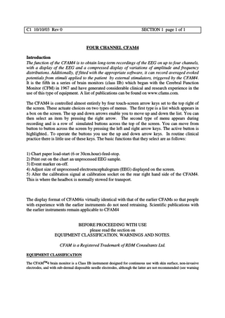
AMPLITUDE AND FREQUENCY DISTRIBUTION PLOT FOR TWO CHANNELS 05:25 002 05:15 05:10 001
05:05
C2
05:25 002 05:15 05:10 001 05:05
C1
100 uVpp
10
1
E
M 37 B 13 A 8.5 T 3.5 D 1 V 0.5S
20k
L
CUTOUT off off LINE 0 0 _ _ MUSCLE 0 0_ _ KOHMS 0 0 _ _ 10Hz calibration signal plot
The left hand trace shows the amplitude distribution of the signal on a logarithmic scale. The axis ticks are at 1,10 and 100uVpp and dotted graticules are in ratio 1,2,4,6,8. In this case it is a steady signal at 100uVpp. at 10Hz. The CFAM4 amplitude can write down to 0.52uVpp and up to 400uVpp, the latter extending above the marked amplitude scale limit of 200uVpp. On the right hand side there are a number of bands. The distance marked M between graticules represents a muscle signal amplitude of 50uVpp. This trace plots from left to right. This is so that any increase of muscle activity points towards any corresponding artefactual increase of energy in the Beta band, plotted to its right. The distances marked B, A, T, D, V between graticules represents 100% of energy in each traditional EEG frequency band, Beta, Alpha, Theta, Delta, with an additional band Vlf for <1Hz. In this case for a 10Hz calibration signal, 100% of the signal energy is in the Alpha band. These traces are plotted from right to left. A single line, representing a weighted mean frequency measure, overlays the percentage frequency plots, the frequency range is 0.5 to 37Hz. S is the percentage time the signal is below 1uVpp, so the distance between graticules again measures 100%. The trace is plotted from right to left. The electrode impedance is measured up to a maximum of 30Kohms, each graticule represents 10Kohm. In this case the 10Hz calibration signal is from a 10 ohm source impedance and so is shown effectively as 0 Kohms on the trace. The impedance trace is plotted from right to left. L indicates the amount of mains frequency (line) interference. It measures up to 100uVpp and writes from the right hand edge towards the zero ohms graticule. Between the amplitude and frequency plots E indicates the event marker output. Each event marker is turned on, and then off by successive up/down arrow keys with the Event button highlighted. Events are numbered consecutively up to 999. If two events occur within one 2 second epoch (at 30cm.hr) they will be amalgamated into one (10second epoch at 6cm.hr). If two events are shown on the screen but are so close that their numerical labelling would overlap, only the first is labelled.
C1 10/10/03 Rev 0
SECTION 1 page 19 of 19
At the left hand edge of the amplitude plot the time ( 24hour clock) is written next to each horizontal graticule. For a chart speed indicated as off, or 30cm.hr, these graticules are at 1 minute intervals. For a chart speed indicated as 6cm.hr. these intervals are 5 minutes.
CUTOUT _ _ LINE 0 0
MUSCLE 0 0
KOHMS 0 0
Below the amplitude and frequency plots, at the bottom of the screen, the current values in micro-volts peak to peak for 50Hz LINE interference and MUSCLE activity, and electrode impedance (KOHMS) are shown numerically, one value for each channel. The channel sequence is left to right, lowest numbered channel to the left. When an input voltage excursion exceeds the limits of the input amplifier, the recorded signal cannot be digitised accurately. In this case, to the right of CUTOUT is written the number, or numbers, of the affected recording channel. Additionally, since there is no reliable input data in that channel, the LINE, MUSCLE and KOHMS values for that channel are replaced by question marks. The data are also written white on black. Further, the CFAM4 camplitude-frequency plot is not written in the 2 second epoch (10second epoch at 6cm.hr) in which the CUTOUT occurred. You can demonstrate this by releasing the head-box and pulling it up off its calibration socket for a moment. Initially, the amplitude/frequency plot will write upwards from the labelled axes every 2 seconds. When it reaches close to the next axis (channel 1), or the top of the display area (channel 2) in the example above, the trace will jump downwards ; 5 minutes if the recording rate is 6cm.hr, or 1 minute if the rate is 30cm.hr..
Chart paper loading. Lift slightly and pull down the side panel. You will see it can be retained in two. To load, let the paper holder rest horizontally. A stack of chart paper should be placed in it, making sure that he rear edge of the pack is retained under small tabs at the rear of the holder. It should be smooth surface on top, rougher surface underneath, with the leading edge of the paper facing left.
Side view of CFAM4
that
Feed a straight leading edge of the paper into the lower edge of the chart mechanism. Usually the drive will detect the presence of the paper and run for a short while to load it. You can also turn on paper feed by one of two methods. Firstly by pressing the small paper feed button on the exposed front panel to the right of the chart mechanism. Secondly, when there is no paper in the drive, the chart button, CHART, on the display should have as its second
paper tension release lever OUT IN
line
paper pack
paper feed button
C1 10/10/03 Rev 0
SECTION 1 page 20 of 20
"paper?", indicating that there was no paper in the mechanism. If with this button highlighted you press the up arrow, paper feed should commence and the label change to loading. In either case the chart mechanism roller may vibrate until it picks up the paper leading edge. It will then pull the paper through the mechanism. If you have initiated the feed from the front panel button, take your finger off. The paper will continue to feed until a little has come out of the mechanism and it will then stop automatically. If feeding has been started from the screen CHART button, paper feed will continue until you press the up arrow key again, when the button message will change to the selected paper rate 30cm.hr or 6cm.hr. Normally the paper feed starts automatically as soon as you push paper into the mechanism. The chart mechanism is programmed to do this automatically but it depends upon it correctly sensing that paper is being pushed into it. If you have difficulty, or you need to straighten the paper in the mechanism, you may wish to release the paper roller tension by pulling down the paper tension release lever which is in a small vertical slot to the top left of the mechanism. A little finger is usually small enough to be able to hook it forwards. You should then be able to pull paper through the mechanism or feed it into, through and out of the mechanism. Please make sure that you return this lever to the upright position. With the paper speed indicated at 30cm.hr or 6cm.hr you may wish to stop the chart until you begin recording from the patient. To do so, with the screen CHART button highlighted, press the up arrow once (or twice) until you get the message off on the screen button. Run out about 10cm of paper then, as you lift up the front cover to lock in its closed position, push it through the chart paper slot.
Recording Release the head-box retention catch by raising its lever to the upper position; the little wheel plus lever, in the guide at the lower back of the head-box stow and calibrate position. Slide the head-box up and out of the guides. There are a number of methods which may be used to place the head-box electrode input sockets near to the patient’s head. a) Place the head-box on the pillow near the patient’s head. The slots in the flanges of the headbox are for you to put safety pins through. NEVER COVER THE HEADBOX , it generates heat and will definitely overheat and may become dangerous if you place it under a pillow. b) The flanges on the sides of the head-box are intended to be used to retain the head-box to a supporting plate which may be clamped to a bed-head, incubator or operating table rail. As the particular preference varies between customers this may be effected to order by the Hospital’s Medical Physics or equivalent department. c) Tapes may be threaded through the slots in the flanges and tied on to a suitable support. If you use this method please ensure that the tapes go up through the slots and over the headbox body and down through the slot in the opposite side.