Richard Wolf
1 CCD ENDOCAM Instruction Manual Index : 12-04-3.0
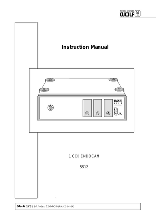
Instruction Manual
27 Pages
Preview
Page 1
Instruction Manual
1 CCD ENDOCAM
E
1 CCD ENDOCAM 5512
GA--A 173 / en / Index: 12--04--3.0 / ÄM: KG 04--243
Important general instructions for use Ensure that this product is only used as intended and described in the instruction manual, by adequately trained and qualified personnel, and that maintenance and repair is only carried out by authorized specialized technicians. Operate this product only in the combinations and with the accessories and spare parts listed in the instruction manual. Use other combinations, accessories and wearing parts only if they are expressly intended for this use and if the performance and safety requirements are met. Reprocess the products before every application and before returning them for repair as required by the instruction manual in order to protect the patient, user or third parties. Subject to technical changes! Due to continuous development of our products, illustrations and technical data may deviate slightly from the data in this manual. CAUTION -- USA only: Federal law restricts this unit to be used or sold, except under the supervision of a medical doctor.
Safety instructions and levels of danger Symbol
Level of danger WARNING! Failure to observe can result in death or severe injury. CAUTION! Failure to observe can result in slight injury or damage to the product.
. .
IMPORTANT! Failure to observe can result in damage to the product or surrounding. NOTE! Tips for optimum use and other useful information.
GERMANY RICHARD WOLF GmbH D--75438 Knittlingen Pforzheimerstr. 32 Tel.: (..49)--(0)7043--35--0 Fax:(..49)--(0)7043--35300 MANUFACTURER
USA RICHARD WOLF Medical Instruments Corp. 353 Corporate Woods Parkway Vernon Hills, Illinois 60061 Tel.: 847--913 1113 Fax: 847--913 1488
UK RICHARD WOLF UK Ltd. Waterside Way Wimbledon SW 17 0HB Tel.: 020--8944 7447 Fax: 020--8944 1311
E--mail: [email protected] Internet: www.richard--wolf.com
E--mail: sales&[email protected] Internet: www.richardwolfusa.com
E--mail: [email protected] Internet: www.richardwolf.uk.com
BELGIUM N.V. Endoscopie RICHARD WOLF Belgium S.A. Industriezone Drongen Landegemstraat 6 B--9031 Gent --Drongen Tel.: +32 9.280.81.00 Fax: +32 9.282.92.16
FRANCE RICHARD WOLF France S.A.R.L. Rue Daniel Berger Z.A.C. La Neuvillette F--51100 Reims Tel.: +33 3.26.87.02.89 Fax: +33 3.26.87.60.33
AUSTRIA RICHARD WOLF Austria Ges.m.b.H. Wilhelminenstraße 93 a A--1160 Wien Tel.: +43 1-- 405 51 51 Fax: +43 1-- 405 51 51--45
E--mail: [email protected]
E--mail: [email protected]
E--mail: [email protected] Internet: www.richard--wolf.at
GA--A 173
0
Contents 1 1.1 1.2 1.2.1 1.3 1.3.1 1.3.2 1.4 1.4.1 1.4.2 1.4.3 1.4.4
General information... Symbols... Intended use... Contraindications... Combinations... General requirements on products/components of a combination... Specific requirements on the products/components of a combination... Electromagnetic compatibility (EMC)... Video mode using BNC connections... Legend... Video mode using S video connections... Legend...
1 1 1 1 2 2 3 3 5 5 6 6
2 2.1 2.1.1 2.2 2.2.1 2.3 2.3.1
Illustration... Front view... Legend... Rear view... Legend... Illustration of camera head with cable... Legend...
7 7 7 7 7 8 8
3 3.1 3.1.1 3.2 3.2.1 3.3 3.4
Setup... Preparation... Legend... Connecting the camera heads to the objective lenses... Camera head with C--mount objective lens... Color bar test picture... Adjusting the monitor...
9 10 10 11 11 12 12
4 4.1 4.2
Checks... 13 Visual check... 13 Functional check... 13
5 5.1 5.2 5.3 5.3.1 5.3.2 5.3.3 5.3.4
Use... Operation... Controls and modes... Use... White balance... Image brightness enhancement (GAIN)... Automatic brightness control (shutter function)... Remote control via camera head...
14 14 14 15 15 15 15 16
6 6.1 6.2 6.2.1 6.2.2 6.2.3 6.2.4 6.2.5 6.3 6.3.1
Reprocessing and maintenance... Reprocessing of device... Reprocessing of camera head... Decontamination by immersion... Manual cleaning... Checking after cleaning... Disinfection... Gas sterilization... Maintenance... Maintenance intervals...
17 17 17 17 17 17 18 18 18 18
GA--A 173
I
7 7.1 7.2 7.2.1 7.2.2 7.3 7.4 7.5 7.5.1 7.5.2
II
Technical description... Trouble shooting... Technical Data... Interfaces... Technical data of camera head... Operating, storage, transport and shipping conditions... Spare parts and accessories... Replacing parts... Device fuses... Disposal of the product, packing material and accessories...
19 19 21 21 22 22 22 23 23 23
GA--A 173
1
General information
1.1
Symbols Symbols
Meaning Attention, consult ACCOMPANYING DOCUMENTS Off (power: disconnection from the mains) On (power: connection to the mains) Equipotentiality Fuse
µ
Alternating current (AC) TYPE CF APPLIED PART Image brightness enhancement (GAIN) Automatic white balance (AWB)
E
Shutter function ON/OFF Data output (VIDEO, S--VIDEO, REMOTE) A Registered Trademark of ETL, a Recognized Testing Laboratory, listing compliance as Medical Electrical Equipment to standard CAN/CSA C 22.2 No. 601.1 (c) and UL 60601--1 (us) Identification in conformity with Medical Devices Directive 93/42/EEC only valid if the product and/or packaging marked with this symbol. Products of category IIa and above, as well as sterile products or products with measuring function pertaining to category I, are additionally marked with the code number of the notified body (0124)
1.2
Intended use The 1 CCD ENDOCAM 5512 is designed for video endoscopy and video microscopy. It can be used for both diagnostic and therapeutic interventions. In connection with video recorders/video printers and other video equipment it can be used for recording or storage of video images.
CAUTION! In case of device failure. For therapeutic applications a second similar camera should be available. 1.2.1
Contraindications Contraindications directly related to the product are presently unknown. On the basis of the patient’s general condition the physician/surgeon in charge must decide whether the planned use is possible or not. For further information see the latest medical literature.
GA--A 173
1
1.3
Combinations .
1.3.1
IMPORTANT! In addition to this instruction manual follow the manuals of the products used in combination with this product.
General requirements on products/components of a combination The general requirements depend on whether the products/components are inside or outside the patient environment. Patient environment
R = 1.5 m h = 2.5 m Patient environment
Acc. to UL 60601--1: R = 1.83 m (6 feet) ; h = 2.29 m (71/2 feet)
Medically used room Inside the patient environment
MP
MP
µ
µ
MP
NMP
µ
µ
MP
NMP
µ
outside the patient environment
**
Non--medically used room
Requirements / measures Leakage currents to clause 19 IEC/EN 60601--1--1 *
--
--
--
--
--
a) additional protective earth connection (to be clarified with manufacturer), or
MP
b) with additional isolating transformer **
NMP
µ MP
NMP
µ
µ
MP
MP or NMP
µ
µ
additional isolating transformer according to IEC/ EN 60601--1--1 **
MP = NMP =
--
--
additional separating device according to IEC/ EN 60601--1--1
a) common protective earth connection, or b) additional protective earth connection (to be clarified with manufacturer), or c) additional separating device (to avoid earth/ground loops in the case of a potential difference) Functional connection
µ power supply grid
medical electrical device according to IEC/ EN 60601--1, UL 60601--1, CSA C22.2 No. 601 non--medical electrical device in accordance with the relevant product--specific IEC/ EN/ UL/ IEC standards
* If connected via a joint mains/power cord under normal conditions the earth leakage current of the system must not exceed 500 µA (300 µA for systems in acc.with UL 60601--1).
** e.g. Richard Wolf Video Trolley with ”isolating transformer”.
2
GA--A 173
1.3.2
Specific requirements on the products/components of a combination .
1.4
IMPORTANT! Persons combining products to form a system are responsible for not impairing the system’s compliance with the performance and safety requirements, and that the technical data and the intended use are adequately fulfilled. Electromagnetic interference or other types of interference occurring between this product and other products can cause failures or malfunctions. When selecting the system components ensure that they meet the requirements for the medical environment they are used in, in particular IEC/ EN 60601--1--1. In case of doubt contact the manufacturer(s) of the system components. Do not touch connecting devices for electrical connections between the different components (such as signal input and output connections for video signals, data exchange, control circuits, etc.) and the patient at the same time.
Electromagnetic compatibility (EMC)
NOTE: The device or system in the following called product always relates to the 1 CCD ENDOCAM 5512. Guidance and manufacturer’s declaration -- electromagnetic emissions The product is intended for use in the environment specified below. The user should assure that the product is used in such an environment. Emissions measurement/test
Compliance
Electromagnetic environment -- Guidance
HF emissions to CICPR 11
Group 1
The product uses HF energy for its internal function. The HF emission level is extremely low and it is not likely to cause any interference in nearby electronic equipment.
HF emissions to CISPR 11
Class B
Harmonic emissions to IEC 61000--3--2
Class A
In conformity with IEC 61000--3--3 “Voltage fluctuations / flicker emissions”
The product is suitable for use in all establishments, including domestic establishments and those directly connected to the public low--voltage power supply network that supplies buildings used for domestic purposes.
Guidance and manufacturer’s declaration -- electromagnetic immunity The product is intended for use in the environment specified below. The user should assure that the product is used in such an environment. Immunity tests
IEC 60601 test level
Compliance
Electromagnetic environment -- guidance
Electrostatic Discharge (ESD) to IEC 61000--4--2
± 6 KV contact ± 8 KV air
Yes
Floors should wood, concrete or ceramic tile. If the floors are covered with synthetic material, the releative humidity should be at least 30%.
Electrical fast transients, bursts to IEC 61000--4--4
± 2 KV for power supply lines ± 1 KV for input/output lines
Yes
Mains/line power quality should be that of a typical commercial or hospital environment.
Surge voltage (surges) to IEC 61000--4--5
± 1 KV differential mode ± 2 KV common mode
Yes
Mains/line power quality should be that of a typical commercial or hospital environment.
Voltage dips, short interruptions and voltage variations on power supply input lines to IEC 61000--4--11
Voltage dip for 0.5 cycle > 95% UT * Voltage dip for 5 cycles > 60% UT * Voltage dip for 25 cycles > 30% UT * Voltage dip for 5 sec > 95% UT *
Yes
Mains/line power quality should be that of a typical commercial or hospital environment. If the user of the product requires continued operation during power mains/line interruptions it is recommended that the product be powered from an uninterruptible power supply or battery.
Power frequency (50/60 Hz) magnetic field, to IEC 61000--4--8
3 A/m
Yes
Power frequency magnetic fields should be at levels characteristic of a typical location in a commercial or hospital environment.
* NOTE: UT is the line/mains voltage prior to application of the test level.
GA--A 173
3
Guidance and manufacturer’s declaration -- electromagnetic immunity for products that are not life--supporting The product is intended for use in the environment specified below. The user should assure that the product is used in such an environment. Immunity test
Compliance level
IEC 60601 test levels
Electromagnetic environment -- guidance
Portable and mobile RF communications equipment should be used no closer to any part of the product, including cables, than the recommended separation distance calculated from equation applicable to the frequency of the transmitter. Recommended separation distance:
Conducted HF interference to IEC 61000--4--6
d = 1.2 p P d = 1.2 p P for 80 MHz to 800 MHz d = 2.3 p P for 800 MHz to 2.5 GHz
3 Vrms 150kHz to 80 MHz Yes
Radiated HF interference to IEC 61000--4--3
REMARKS:
3 V/m 80 MHz to 2.5 GHz
P = Nominal power output rating of the transmitter in watts (W) (according to the transmitter manufacturer)
d = recommended separation distance in meters (m) Field strengths from fixed RF transmitters, as determined by an electromagnetic site survey1, should be less than the compliance level in each frequency range2. Interference may occur in the vicinity of devices with the following symbol:
At 80 MHz and 800 MHz the higher frequency range applies. These guidelines may no apply in all situations, as the propagation of electromagnetic waves is affected by absorption and reflexion from buildings, objects and people.
1 = The field strength of fixed transmitters (e.g. base stations for radio telephones, land mobile radios, amateur radio, radio broadcast and TV broadcast, ...), cannot be predicted theoretically with accuracy. To assess the EMC environment due to fixed transmitters an electromagnetic site survey should be conducted. If the measured field strength in the location in which the product is used exceeds the applicable compliance level above, the product should be observed to verify normal operation. If abnormal performance is observed, additional measures may be required, such as reorienting or relocating the product. 2 = Over the frequency range between 150 kHz and 80 MHz the field strength should be below 3 V/m.
The recommended separation distances between portable and mobile HF telecommunication devices and devices which are not life--supporting The product is intended for use in an electromagnetic environment with HF disturbances are controlled. The user can help prevent electromagnetic interference by maintaining a minimum distance between portable and mobile HF telecommunications equipment and the product. Separation distance as a function of transmitter frequency (m)
Rated nominal output power of the transmitter (Watts)
150 kHz to 80 MHz
80 MHz to 800 MHz
800 MHz to 2.5 GHz
0.01
0.12
0.12
0.23
0.1
0.38
0.38
0.73
d = 1.2 p P
d = 1.2 p P
d = 2.3 p P
1
1.2
1.2
2.3
10
3.8
3.8
7.3
100
12
12
23
For transmitters rated at a nominal output power not listed in the table above, the recommended separation distance (d) in meters (m) can be determined using the applicable equation (observe frequency). P = nominal power of the transmitter in Watts (W). REMARKS: At 80 MHz and 800 MHz the higher frequency range applies. These guidelines may no apply in all situations. Electromagnetic propagation is affected by absorption and reflexion from buildings, objects and people.
4
GA--A 173
1.4.1
Video mode using BNC connections
Light projector VIDEO--OUT
VIDEO--IN
1
MONITOR MONITOR
VIDEO--OUT VIDEO--IN
VIDEO--IN MONITOR
2
5
1 CCD ENDOCAM VIDEO--OUT VIDEO--OUT
3 VIDEO--IN
E
Video Video printer printer
4
VIDEO--OUT Video recorder Video recorder VIDEO--IN
1.4.2
Legend .
NOTE! Connect only the cables listed in the following table. Set the monitor to FBAS mode.
Devices connected
Cable connections
Direct connection
BNC cable [1] and [2]
with video recorder / printer ...
BNC cables [2] , [3] , [4] and [5]
Direct connection 1 CCD ENDOCAM 5512
GA--A 173
BNC
Light projector
BNC
Monitor
5
1.4.3
Video mode using S video connections
Light projector VIDEO--OUT
VIDEO--IN
1
MONITOR MONITOR S--VIDEO--IN
VIDEO--IN
S--VIDEO--IN MONITOR
2
6
5
1 CCD ENDOCAM
S--VIDEO--OUT VIDEO--OUT S--VIDEO--OUT
S--VIDEO--IN
Video Video printer printer
E
S--VIDEO--OUT
3
4
S--VIDEO--OUT Video recorder Video recorder S--VIDEO--IN
1.4.4
Legend .
NOTE! Connect only the cables listed in the following table.
Devices connected
Cable connections
Direct connection
BNC cable [1] , [2] and S--video cable [6] (If the light projector is equipped with a 75 Ohm connection the BNC cable [1] is not required)
With Video recorder / printer ...
BNC cable [1] , [2] and S--video cable [3] , [4] and [5] (If the light projector is equipped with a 75 Ohm connection the BNC cable [1] is not required)
Direct connection
1 CCD ENDOCAM 5512
6
S--VIDEO
BNC
Light projector
BNC
Monitor
GA--A 173
2
Illustration
2.1
Front view
1 CCD ENDOCAM
1
E
2.1.1 1 2 3
2.2
5
4
Mains/power ON/OFF switch ”Automatic White Balance” (AWB) button ”Image Brightness” (GAIN) button
4 5
3
2
Legend ”Shutter ON/OFF” button Camera socket
Rear view
12
S--VIDEO
REMOTE
VIDEO
5512.751 -- USA
11
10
9
8
7
6
FEDERAL LAW RESTRICTS THIS UNIT TO BE USED OR SOLD, EXPECT UNDER THE SUPER-VISION OF A MEDICAL DOCTOR.
T1,0 250V
2.2.1
Legend
6 7 8 9
Video output sockets S--video output sockets Service connector Remote control connector for recorder/printer
GA--A 173
10 11 12
Replace fuse as marked
Identification plate Mains/power input connector with fuse holder Equipotential connector
7
2.3
Illustration of camera head with cable
19
20
18
17 14
16
2.3.1
Legend
14
Camera head
15
18
Protective cap for camera head
15
Camera plug
19
Model and series no
16
Protective cap for camera plug
20
Classification of applied part
17
Remote control button for recorder/printer or white balance
8
GA--A 173
3
Setup WARNING! The device is not protected against explosions. Explosion hazard. Do not operate this device in areas where there is a danger of explosion.
. NOTE!
Check that the mains/line voltage is the same as the voltage specified on the identification plate. Connect the device only with the supplied power cable or a power cable meeting the same specifications. CAUTION! Danger of faults and malfunctions. To guarantee the safety of the user, the patient and others use only accessories and spare parts specified by the manufacturer of this product. Other accessories or spare parts can cause the emission of increased electromagnetic radiation or reduced immunity against interference.
. IMPORTANT!
Medical devices are subject to special precautions with regard to electromagnetic compatibility (EMC). Make sure you observe the notes on EMC for installation and operation. Medical electrical devices can be influenced by mobile HF communication devices. If it is necessary to stack the devices or place them next to each other and HF interference is observed, make sure you observe the intended use of the devices.
GA--A 173
9
3.1
Preparation
. IMPORTANT!
Never direct the camera head towards the sun or bright light sources in the vicinity. High--energy radiation in the visible and ultraviolet wave lengths can damage the CCD chip surface which may cause color artefacts and image noise. If the camera head is not used make sure that the protective cap or, with the objective lens in place, the lens protective cap is put on. Never pinch, squeeze or excessively bend the camera cable.
14
18
Z Connect auxiliary devices such as the monitor and light projector as shown in connection diagrams chapter 1. Z Switch on the 1 CCD ENDOCAM. Z A color bar test picture appears on the monitor. Z Remove protective cap (18) from camera head (14). Z Then screw objective lens onto camera head. (see 3.2) Z Connect camera head to camera controller ensuring that the dot mark of the camera plug aligns with that of the camera controller.
Light projector
23
22
3.1.1
14
E
Legend 14 21
10
21
Camera head Objective lens
22 23
Endoscope Light cable
GA--A 173
3.2
Connecting the camera heads to the objective lenses
. NOTE!
Before assembling the objective lens verify that glass surfaces of objective lens and camera head are dry and dust--free. Remove any contaminants with a cotton swab soaked in alcohol (wooden or plastic sticks, no metal).
3.2.1
Camera head with C--mount objective lens It is possible to connect standard C--mount objective lenses to the camera head. Z Unscrew protective cap from C--mount thread of objective lens. Z Screw objective lens onto camera head by turning clockwise.
open
close
GA--A 173
11
3.3
Color bar test picture The color bar test picture of the camera serves to check color intensity and tint of the monitor. With the help of the color bar signal, video and S--video signals can be adjusted to optimum color rendition. Z Pulling off the camera controller causes the camera to switch from camera picture to color bar signal.
3.4
Adjusting the monitor Z Activate the color bar test picture by pulling off the camera plug from the camera controller. Z Press ”RESET” on the monitor. Z Set the contrast control of the monitor to the lighting conditions in the room or Z Set the monitor contrast control to the middle position or adjust to ambient conditions, respectively. Z Set brightness control on monitor to middle position. Z Set color intensity control on the monitor to middle position. Z Set color phase (tint) control to middle position (only NTSC) or adjust the colors with the help of the color bar test pattern. ' Switch the monitor to monochrome mode for blue (blue only). Adjust the chroma (and in the case of NTSC also the color phase) control so that the four bars appear with the same brightness or ' If the monitor is not suitable for monochrome mode adjust color to your own sense of color.
. IMPORTANT!
The last device in the video chain must be terminated with 75 Ohms (75 Ohms ”ON”). The devices within the video chain must be set to high impedance (75 Ohms ”OFF”).
12
GA--A 173
4
Checks
. IMPORTANT!
Run through the checks before every application.
4.1
Visual check Z Check devices, instruments and accessories for damage, hygiene and completeness. Z Check all connection cables for damage. Z Lettering and labels must be complete and easily legible.
4.2
Functional check Z Connect camera head to camera controller and attach endoscope to objective lens. Z Make sure that connection is tight. Z Switch on the camera controller. ' The mains/power switch is lit. Z Switch on all other video devices. ' Direct endoscope at an object and check rendering (picture). Z Perform settings as described in chapter 3, if necessary.
GA--A 173
13
5
Use
5.1
Operation The camera controller provides a video signal that can be displayed on a monitor or recorded by means of a video recorder or video printer. Color properties of the illumination are referred to as color temperatures and measured in Kelvin (K). Higher color temperatures are blueish, lower color temperatures are reddish. In order to reproduce or render a picture in true colors a new setting of the white balance is required both before initial setup and each time the light projector is changed. The white balance procedure adjusts color amplification for the red and blue portion of the video image in such a way that is suits the color temperature of the light projector helping the 1 CCD ENDOCAM to render optimum color results. White objects are thus rendered completely white. The 1 CCD ENDOCAM provides a white balance color temperature range between 2250 K and 6000 K.
5.2
Controls and modes Z The ”automatic white balance” button serves to trigger the white balance procedure. Z Pressing the ”image brightness” (GAIN) button will increase the camera’s gain factor.
E
14
Z Pressing the ”shutter function” button switches the 1 CCD ENDOCAM’s automatic brightness control on and off.
GA--A 173
5.3
Use
5.3.1
White balance
. IMPORTANT!
If during an endoscopic intervention the white balance procedure is started by mistake, the colors are not rendered correctly. In this case repeat the white balance procedure outside the body using a white object. The values once set remain active even after the camera is switched off.
. IMPORTANT!
Perform a white balance procedure before every use. White balance is not required if the same instruments and the same light source are used. Z Switch on the light projector and direct the endoscope at a white surface. ' Ensure that no extraneous light and no colored objects are in the camera’s field of view.
Z Press the ”automatic white balance” button, ' successful white balance is acknowledged by a brief acoustic signal and the button is lit again. or press the button on the camera head (17) for more than 1 second. ' A white balance is performed after the second sound signal. Successful white balance is acknowledged by a sound signal of approximately 1 second.
17
5.3.2
Image brightness enhancement (GAIN) If parts of the scene or the entire scene is underexposed such as during inspection of a tubular object or if the distance between the distal tip of the endoscope and the object observed, it is possible to increase the camera’s gain.
. NOTE!
With the gain activated and excessive distance between the endoscope tip and the target object image noise will increase.
5.3.3
Automatic brightness control (shutter function) E
Thanks to the shutter function of the 1 CCD ENDOCAM, uncontrolled light projectors or light projectors with deactivated video control can be used. Advantage of the shutter function: very quick adjustment of image brightness.
. IMPORTANT!
To avoid unnecessary heating of the endoscope when using the shutter function, set the illumination of the light projector to a medium value. The shutter function should not be used in connection with the light projector’s video control function (switch off video control) as this can lead to undesirable fluctuations in image brightness.
GA--A 173
15
5.3.4
Remote control via camera head L Recording remote control (button 17) Pressing button (17) on the camera head briefly (for less than 1 second) serves to remote--control a video recorder or video printer which connects to the “remote” socket. A short acoustic signal is sounded.
17
To prepare the recording remote control from the camera button, press the ”RECORD” button (on some video recorders both the ”RECORD and PLAY” button at the same time) as well as the ”PAUSE” button. Follow the video recorder manufacturer’s instruction. Commercially available video recorders (VHS, S--VHS, VIDEO--8) can be remote--controlled if they are equipped with a suitable REMOTE input socket.
L White balance Trigger the white balance procedure by pressing the button for some time (longer than 1 second). A brief acoustic signal is sounded at the beginning and an acoustic signal of approx. 1 second is sounded to indicate successful completion of the white balance.
. IMPORTANT!
If during an endoscopic intervention the white balance procedure is started by mistake, the colors are not rendered correctly. In this case repeat the white balance procedure outside the body using a white object.
16
GA--A 173