Richard Wolf
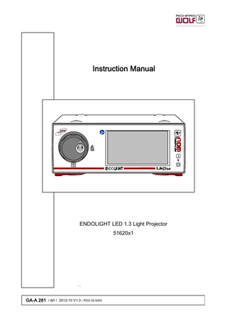
ENDOLIGHT LED 1.3 Light Projector 51620x1 Instruction Manual V1.0 Oct 2012
Instruction Manual
41 Pages
Preview
Page 1
Instruction Manual
ENDOLIGHT LED 1.3 Light Projector 51620x1
GA-A 281 / en / 2012-10 V1.0 / PDG 00-0000
Important general notes and instructions for use Make sure that this product is used only as intended and described in this instruction manual, by adequately trained and qualified medical personnel, and that maintenance and repair are only carried out by authorized experts. Use the product only in the combinations and with the accessories and spare parts specified in this instruction manual. Use other combinations, accessories and replacement parts only if they are expressly intended for the planned application and if the performance characteristics and safety requirements are not impaired. Do not alter the product in any way. Reprocess the products before every application and before returning them for repairs as required by the instruction manual in order to protect the patient, user and others. Immediately upon receipt, check the product and its accessories for completeness and possible damage. Should the shipment give right to complaints, please inform the manufacturer or supplier immediately. Subject to technical changes! Due to ongoing developments, the illustrations and technical data may deviate slightly.
Safety instructions and levels of danger Symbols
Level of danger
WARNING!
Failure to observe can result in death or serious injury.
CAUTION !
Failure to observe can result in slight injury or damage to the product.
.
IMPORTANT !
.
NOTE !
Failure to observe can result in damage to the product or surroundings. Tips for optimum use and other useful information.
GERMANY RICHARD WOLF GmbH 75438 Knittlingen Pforzheimerstr. 32 Telephone: +49 70 43 35-0 Telefax: +49 70 43 35-300 MANUFACTURER [email protected] www.richard-wolf.com BELGIUM / NETHERLANDS N.V. Endoscopie RICHARD WOLF Belgium S.A. Industriezone Drongen Landegemstraat 6 9031 Gent Drongen Telephone: +32 92 80 81 00 Telefax: +32 92 82 92 16 [email protected] www.richard-wolf.be Marketing Office U.A.E RICHARD WOLF Middle East P.O. Box 500283 AL Thuraya Tower 1 9th Floor, Room 904, Dubai Telephone: + 9 71 43 68 19 20 Telefax: + 9 71 43 68 61 12 [email protected] www.richard-wolf.com
GA-A 281
USA RICHARD WOLF Medical Instruments Corporation 353 Corporate Woods Parkway Vernon Hills, Illinois 60061 Toll Free: 001 (800) 323 - 9653 Phone: 001 (847) 913 - 1113 Fax: 001 (847) 913 - 1488 [email protected] www.richardwolfusa.com FRANCE RICHARD WOLF France S.A.R.L. Rue Daniel Berger Z.A.C. La Neuvillette F-51100 Reims Telephone: +33 3 26 87 02 89 Telefax: +33 3 26 87 60 33
UK RICHARD WOLF UK Ltd. Waterside Way Wimbledon SW17 0HB Telephone: + 44 20 89 44 74 47 Telefax: + 44 20 89 44 13 11 [email protected] www.richardwolf.uk.com
[email protected] www.richard-wolf.com
AUSTRIA RICHARD WOLF Austria Ges.m.b.H. Wilhelminenstraße 93 a A-1160 Vienna Telephone: +43 14 05 51 51 Telefax: +43 14 05 51 51 45
INDIA RICHARD WOLF India Private Ltd. JMD Pacific Square No. 211 A, Second Floor Behind 32nd Milestone Gurgaon - 122 001 National Capitol Region Telephone: + 91 12 44 31 57 00 Telefax: + 91 12 44 31 57 05 [email protected] www.richard-wolf.com
0
Contents 1 1.1 1.2 1.3 1.4 1.4.1 1.4.2 1.5 1.5.1 1.5.2 1.6 1.7
General information... Symbols... Intended use... Indications and field of application... Contraindications and side effects... Contraindications... Side effects... Combinations... Potential equalization... Requirements for the products / components of a combination... Electromagnetic compatibility (EMC)... Wiring schematic - Light projector in video mode...
1 1 2 2 2 2 2 2 3 3 4 6
2 2.1 2.2
Illustration... Front view... Rear view...
7 7 8
3 3.1 3.2 3.3
Setup... 9 Language settings... 10 Selecting the light socket... 10 Preparation... 11
4 4.1 4.2 4.2.1 4.2.2 4.2.3
Checks... Visual check... Function check... Device function after switching on the device... Switching ON and OFF the LED... Automatic brightness adjustment using the "dialog" function...
12 12 12 12 13 13
5 5.1 5.2 5.2.1 5.2.2 5.2.3 5.3 5.3.1 5.3.2 5.4 5.5 5.6 5.7 5.7.1 5.7.2 5.7.3 5.8 5.8.1 5.8.2 5.8.3
Use... Operating principle... Controls and modes... "Dialog" function... "Safe start" function... Temperature protection circuit... Control sequence and menu structure... Overview - control sequence... Overview - menu structure... Menu levels... Menu control and touchscreen functions... Profiles... Device parameters... Adjusting the device parameters... Service... General service... Operation of light projector... Switching ON and OFF the LED... Automatic restart of the device (e.g. after power failure)... Brightness control...
14 14 14 14 15 15 15 15 16 17 17 19 21 21 23 23 24 25 25 26
GA-A 281
I
5.8.4 5.9 5.9.1 5.9.2 5.9.3 5.9.4 5.9.5 5.9.6 5.9.7
Taking out of service... Overview of operator messages... Structure of operator messages... Message types... Functionality of control elements... Operator's messages (green)... LOW error (turqoise)... MEDIUM error (yellow)... HIGH error (red)...
26 27 27 27 27 28 29 30 30
6 6.1 6.2 6.3 6.4
Operation within the core system... Functional principle within the core system... Combining and controlling the device... Setting the system ID... Connection to the core system...
31 31 31 31 32
7 7.1 7.2 7.2.1
Reprocessing and maintenance... Reprocessing of device... Maintenance... Maintenance intervals...
33 33 33 33
8 8.1 8.1.1 8.1.2 8.1.3 8.1.4 8.2 8.2.1 8.2.2 8.3 8.4 8.5 8.5.1
Technical description... Troubleshooting... Device error... Lamp function errors... Fault in video mode... Fault in the core system... Technical data... Technical Data of LED Light Source... Interfaces... Operating, storage, transport and shipping... Spare parts and accessories... Replacing the device fuses... Disposal of product, packaging material and accessories...
34 34 34 34 34 34 35 35 35 35 36 37 37
II
GA-A 281
1
General information
1.1
Symbols Symbols
Designation Attention, Caution Follow the instruction manual OFF (no power supply, separation from mains) ON (connection to the mains / line voltage) Potential equalization Power / Mains fuse Alternating current (AC)
μ
TYPE CF APPLIED PART Cold light Alarm Signal sound Signal sound switched off Keyboard Operating hours Data input Data output High voltage Heat dissipation Manufacturer Recycle the product separately. Do not discard together with other waste. XX XX
Permissible temperature range
XXhPa
Permissible atmospheric pressure range XXhPa
GA-A 281
1
Symbols
Designation
XX%
Permissible humidity range XX%
A Registered Trademark of a Recognized Testing Laboratory, confirming compliance to the standard of Medical Electrical Equipment CAN/CSA C22.2 No.60601-1 (c) and ANSI/AAMI ES60601-1 (us) Identification in conformity with medical devices directive 93/42/EEC only valid if the product and/or packaging is marked with this symbol. Products of category IIa and above, as well as sterile products or products with measuring function of category I, are additionally identified with the code no. of the notified body (0124).
1.2
Intended use The ENDOLIGHT LED 1.3 Light Projector provides light for medical ex aminations as well as diagnostic and therapeutic applications specifically in endoscopy. This product is designed exclusively for use by specialized medical per sonnel and may only be applied by medically qualified and adequately trained doctors.
1.3
Indications and field of application
Therapy and diagnosis in conjunction with endoscopic accessories.
CAUTION! This device or the LED may fail. In the case of therapeutic applications, a second light projector with the same features should be available.
.
NOTE! We recommend reading relevant literature for the planned application.
1.4
Contraindications and side effects
1.4.1
Contraindications
1.4.2
Side effects
1.5
Combinations
Contraindications directly related to the product are presently unknown. On the basis of the patient's general condition the doctor in charge must decide whether the planned use is possible or not. For further notes and instructions please refer to the latest medical litera ture. Side effects directly related to the product are currently unknown.
.
2
IMPORTANT! In addition to this instruction manual, follow the manuals for the products used in combination with this product.
GA-A 281
1.5.1
Potential equalization The potential equalization cable establishes a direct connection between a medical electrical de vice and an equipotential bonding rail. It serves to equalize differences in potential between enclosures of electrical equipment and firmly installed conductive parts in the patient environment.
1.5.2
Requirements for the products / components of a combination 1.5m
1.5m The general requirements depend on whether the products / components are inside or outside the patient environment.
1.5m
IEC 60601-1, 3. Ed.
Medically used room inside the patient environment MP
MP
~
~
MP
MP
~
NMP
~
~
MP
NMP
MP
Non-medically used room
-
-
Requirements / measures Leakage currents to section 16.6 IEC 60601-1:2005 / EN 60601-1:2006 *
Verification of the total patient leakage current
**
MP
~
outside the patient environment
**
-
Verification of leakage currents
**
a) additional protective earth connection (consult the corresponding manufacturer),
-
or
NMP
b) additional isolating transformer for medical applications **
~ MP
NMP
~ MP / NMP
MP
~
**
MP
NMP
~
~
MP
MP / NMP
~
~
additional "isolating transformer" to IEC/ EN60601-1 ** Functional connection MP NMP
* **
Verification of leakage currents a) no plugs with metal housing, or b) additional isolation device (to avoid voltage differentials)
-
~
Verification of leakage currents a) common protective earth connection, or b) additional protective earth connection at MP (clarify with the corre ponding manufacturer), or c) additional isolation device (to avoid voltage differentials), or d) no plugs with metal housing in the patient environment
additional isolating device to IEC/ EN 60601-1
Multiple socket strip
Power supply grid
= medical electrical device to IEC/ EN 60601-1, ANSI/AAMI es60601-1, CSA C22.2 No. 60601-1 08 = non-medical electrical device in accordance with product-specific IEC/EN/UL standards When connected via a multiple socket strip under standard conditions the earth leakage current of the power bar must not exceed 5 mA. e.g. Richard Wolf video cart with "isolating transformer"
GA-A 281
3
.
IMPORTANT! The persons combining products to form a system are responsible for not impairing the system's compliance with performance and safety requirements, and that the technical data and the intended use are adequately fulfilled. Possible electromagnetic or other interference that may occur between the product and other products can cause faults or malfunctions. When selecting the system components, make sure that they meet the necessary requirements of the medical envi ronment they are used in, in particular IEC/ EN 60601-1 (3. Edition IEC/EN 60601-1, section 16). In case of doubt contact the manufacturer(s) of the system components. Do not touch connectors for electrical connections between various components (such as signal input connectors and signal output connectors for video signals, data exchange, controls etc.) and the patient at the same time.
.
IMPORTANT! Accessories such as light cables must not have a negative impact on the classification of the applied part and must not have a conductive connection between the light socket and the cold-light connector.
1.6
Electromagnetic compatibility (EMC)
Please observe the following: The device or system in the following called product always relates to the ENDOLIGHT LED 1.3. The product does not have any performance features classified as essential performance features in accordance with IEC/EN 60601-1.
Guidelines and manufacturer's declaration - Electromagnetic emissions The product is intended for use in the environment specified below. The user must assure that the product is used in such an environment. Emissions measurement / test
Compliance
Electromagnetic environment - Guidelines
HF emissions to CISPR 11
Group 1
The product uses HF energy for its internal function. The HF emission level is extremely low and it is not likely to cause any interference in nearby electronic equipment.
HF emissions to CISPR 11
Class B
Harmonic emissions to IEC 61000-3-2
Class A
In conformity with IEC 61000-3-3 “Emission of voltage fluctuations / flicker"
The product is suitable for use in all establishments, including domestic establishments. This also includes establishments directly connected to the public low voltage power supply network that supplies buildings used for domestic purposes.
Guidelines and manufacturer's declaration - Electromagnetic immunity The product is intended for use in the environment specified below. The user must assure that the product is used in such an environment. Immunity tests
IEC 60601 test level
Compliance
Electromagnetic environment - Guidelines
Electrostatic discharge (ESD) to IEC 61000-4-2
6 KV contact discharge 8 KV air discharge
Yes
Floors should be wood, concrete or ceramic tile. With floors made of synthetic material, the relative humidity of the ambient air must be at least 30%.
Electrical fast transience, bursts to IEC 61000-4-4
2 KV for power supply lines 1 KV for input and output lines
Yes
Mains/line power quality should be that of a typical commercial or hospital environment.
Surge voltage (surges) to IEC 61000-4-5
1 KV line to line voltage 2 KV line to ground voltage
Yes
Mains/line power quality should be that of a typical commercial or hospital environment.
Voltage dips, short interruptions and sup ply voltage variations to IEC 61000-4-11
Voltage dip for 0.5 cycle > 95% UT * Voltage dip for 5 cycles 60% UT * Voltage dip for 25 cycles 30% UT * Voltage dip for 5 sec > 95% UT *
Yes
Mains/line power quality should be that of a typical commercial or hospital environment. If the user of the product requires continued operation during power mains/line interruptions it is recommended that the product be powered from an uninterrupti ble power supply or battery.
Power frequency (50/60 Hz) magnetic field, to IEC 61000-4-8
3 A/m
Yes
Power frequency magnetic fields should be at le vels characteristic of a typical location in a com mercial or hospital environment.
* NOTE: UT is the line / mains voltage prior to application of the test level.
4
GA-A 281
Guidelines and manufacturer's declaration - Electromagnetic immunity for products that are not life-supporting The product is intended for use in the environment specified below. The user must assure that the product is used in such an environment. Immunity tests
IEC 60601 test level
Compliance
Electromagnetic environment - Guidelines Portable and mobile RF communications equipment should be used no closer to any part of the product, including ca bles, than the recommended separation distance calculated from equation applicable to the frequency of the transmitter. Recommended separation distance: d = 1.2 p P
Conducted HF interference to IEC 61000-4-6
3 Vrms 150 kHz to 80 MHz
Radiated HF interference to IEC 61000-4-3
3 V/m 80 MHz to 2.5 GHz
d = 1.2 p P for 80 MHz to 800 MHz Yes
d = 2.3 p P for 800 MHz to 2.5 GHz P = Nominal power output rating of the transmitter in watts (W) (according to the transmitter manufacturer)
d = recommended separation distance in meters (m) Field strengths from fixed RF transmitters, as determined by an electromagnetic site survey1, should be less than the compliance level in each frequency range2. Interference may occur in the vicinity of devices with the following symbol:
REMARKS: At 80 MHz and 800 MHz the higher frequency range applies. These guidelines may not apply in all situations. The propagation of elec tromagnetic waves is affected by absorption and reflexion from buildings, objects and people. 1 = The field strength of stationary transmitters (e.g. base station for radio phone, earth to earth radio stations,, amateur radio stations, radio and television transmitters) cannot be exactly predicted in theory. To assess the EMC environment due to fixed transmitters an electromagnetic site survey should be conducted. If the measured field strength in the location in which the product is used exceeds the applicable compliance level above, the product should be observed to verify normal operation. If abnormal performance is observed, additional measures may be required, such as reorienting or relocating the product. 2 = Over the frequency range between 150 kHz and 80 MHz the field strength should be below 3 V/m.
Recommended separation distances between portable and mobile HF telecommunication devices and devices which are not life-supporting The product is intended for use in an electromagnetic environment where HF disturbances are controlled. The user can help prevent electromagnetic interference by maintaining a minimum distance between portable and mobile HF telecommunica tions equipment and the product. Rated nominal output power of the transmitter (W)
Separation distance as a function of transmitter frequency (m) 150 kHz to 80 MHz d = 1.2 p P
80 MHz to 800 MHz d = 1.2 p P
800 MHz to 2.5 GHz d = 2.3 p P
0.01
0.12
0.12
0.23
0.1
0.38
0.38
0.73
1
1.2
1.2
2.3
10
3.8
3.8
7.3
100
12
12
23
For transmitters rated at a nominal output power not listed in the table above, the recommended separation distance (d) in meters (m) can be determined using the applicable equation (observe frequency). P = nominal power of the transmitter in Watts (W). REMARKS: At 80 MHz and 800 MHz the higher frequency range applies. These guidelines may not apply in all situations. The propagation of elec tromagnetic waves is affected by absorption and reflexion from buildings, objects and people.
GA-A 281
5
1.7
Wiring schematic - Light projector in video mode
1.1
1.1
1
2
Legend Direct connection 1
CAN BUS connection cable (option)
1.1
CAN BUS termination (option)
2
Video cable to meet the signal requirements of the camera controller used
.
IMPORTANT! Connection of the CAN BUS connection cable (1) only with interactive camera controller.
If the CAN BUS connection cable is connected, the free CAN BUS connections on the light projector and camera controller must be terminated using the CAN BUS termination resistors (1.1).
6
GA-A 281
2
Illustration
2.1
Front view
3.1
3
2
3.2
1.1
1
Legend 1
Power ON/OFF switch
3
Selector wheel with light sockets (type CF applied part)
1.1
Indicator light for power on/off
3.2
Light socket
2
Touchscreen
3.1
Indication of selected light socket
GA-A 281
7
2.2
Rear view 8
SERVICE
7
5
6
4
9 FEDERAL LAW RESTRICTS THIS UNIT TO BE USED OR SOLD, EXCEPT UNDER THE SUPERVISION OF A MEDICAL DOCTOR.
Legend 4
Potential equalization connector
7
Service interface
5
Fuse plate
8
CAN BUS interface
6
Power input connector with fuse holder
9
Identification plate
8
GA-A 281
3
Setup WARNING! The device is not protected against explosions. Explosion hazard. Do not operate this device in areas where there is a danger of explosion. WARNING! Danger if a power supply without protective earth is used. Danger of electric shock! Connect the device only to a power supply with protective earth con nector.
.
NOTE! The line / mains voltage must correspond with the voltage indicated on the identification plate. Connect the device only via the supplied power cable or a power cable with the same specifications. Do not block any ventilation slots! CAUTION! Danger of faults and malfunctions. To guarantee the safety of the user, patient and others, use only acces sories and spare parts as specified by the manufacturer of this product. Other accessories or spare parts can cause the emission of increased electromagnetic radiation or reduced immunity against interference.
.
IMPORTANT! Medical electrical equipment is subject to special precautions with regard to electromagnetic compatibility (EMC). Make sure you follow the notes on EMC for installation and operation. Medical electrical devices can be influenced by mobile HF communication devices. If it is necessary to stack the devices or place them next to each other and HF interference is observed, make sure that the devices are ope rated as specified in the intended use. CAUTION! Device failure due to automatic over-temperature cut-out. In the case of insufficient air supply, the over-temperature cut-out may be triggered which will shut down the device during use. Units with a cooling device [e.g. fan] require a minimum distance of 15 cm from the wall and unobstructed vent slots. Do not cover any openings required for cooling. To prevent a possible accumulation of heat in the closed system cart, place the devices accordingly and/or provide vent slots.
.
GA-A 281
NOTE! To prevent the ventilation system from aspirating liquids it is not allowed to place any products or objects from which liquids may drip down on top or above the light projector.
9
3.1
Language settings
The language is selected in the Device parameters menu (see section 5). When switching on the device for the first time (setup) as well as during a new start after having reset the device to "factory settings", the required language must be selected. ' Language selection for the “standard setting” (default setting). ' For "User-specific operator profile" it is possible to define a separate language. If a wrong language has been selected and you can no longer call up the general menu for language selection in that language, proceed as fol lows:
Fig. 1
Z Switch off the device and wait for at least 60 seconds. Z Switch on the device and press the device name on the touchscreen until the language selection menu is displayed. ' Then select the required language.
3.2
Selecting the light socket The light projector is equipped with a selector wheel (3) which has 4 dif ferent light sockets to also allow the connection of light cables of other manufacturers. Z Turn the light socket for the light cable to be used to the 3-o'clock posi tion (3.1). ' The manufacturer's code is displayed in the window (3.2). Manufacturer's code W = WOLF
3 3.1
S = STORZ
3.2
O = OLYMPUS A = ACMI
10
GA-A 281
3.3
Preparation
.
NOTE! To achieve optimum light transmission, the fiber bundle diameters of the endoscope and fiber light cable must be the same. Possible consequences when using a fiber light cable with ' excessive diameter: excessive heating at the coupling point with the endoscope ' insufficient diameter: reduced light output, excessive heating of light socket and fiber light cable. For the suitable fiber bundle diameter please refer to the product number of the fiber light cable. ' the two digits to the right of the decimal point in the type number must correspond with the code number on the cold-light connector. Exception: Fiber light cable 8061.933 has a fiber bundle diameter of 3.5 mm.
.
IMPORTANT! In video mode, in conjunction with an interactive camera controller, the brightness of the light projector is controlled via the dialog function (see section 5.2.1). The shutter function of the camera controller must be switched on (ELC ON) and the CAN BUS connection cable between the light projector and the camera controller must be connected.
.
NOTE! Remove the protection foil from the touchscreen before the initial setup.
35
35
Z Connect additional devices such as a monitor and a camera controller in accordance with the connection diagram in section 1. Z Connect the endoscope in accordance with the illustration. CAN BUS Connection cable (option)
22 23
24 25
Legend 22 Fiber light cable 23 Endoscope
GA-A 281
24 25
Camera head with objective lens Camera controller
11
4
Checks .
4.1
IMPORTANT! Run through the checks before and after each use. Do not use the products if they are damaged or incomplete or have loose parts. Return damaged products together with any loose parts for repair. Do not attempt to do any repairs yourself.
Visual check Z Check the device and accessories for damage, loose or missing parts, hygiene and completeness. Z Check all connection cables and hoses for damage. Z Any inscriptions, lettering or labeling necessary for the safe intended use must be legible. ' Missing inscriptions, lettering or labeling leading to wrong handling or reprocessing must be reinstated.
4.2
Function check
.
IMPORTANT! Before you perform the function checks, make sure that the devices are in perfect technical condition and are set up correctly. This must also be guaranteed within the scope of the visual check. This device is equipped with automatic function check routines which automatically detect and report various types of faults. The device detects faults and errors that occur during the self test or during operation.
4.2.1
Device function after switching on the device Z Switch on the device with the power switch. ' When the self test starts also listen to a signal being sounded for checking the speaker function. ' After a successful self test the device is ready for operation. ' If you have generated your own profiles, after 5 seconds without manual profile selection the device automatically switches to the "Standard profile". ' The indicator lamp on the power switch is lit. ' The LED light source is not ON. ' The device cooling fan starts running after switching on the LED
12
GA-A 281
4.2.2
Switching ON and OFF the LED
Light
Light 4.2.3
Switching on the LED: Z Push the “Light" button to switch on the LED. ' If no light cable is connected the LED is switched off. Switching off the LED: Z Push the “Light" button again to switch off the LED.
Automatic brightness adjustment using the "dialog" function
CAUTION! Danger of glare. Do not look into the open end of the light cable when the light cable is connected. Z Connect the interactive camera controller in accordance with section 1. Z Connect the light cable to the light projector. Z Switch on the light projector and the camera controller. Light
Z Push the “Light" button to swich on the LED. Z The dialog function is active as a default setting (see section 5.2.1). Z Illuminate an object with white light. ' The camera controller automatically controls the brightness (ELC ON on camera controller). In this case, manual brightness control is not possible.
GA-A 281
13
5
Use
5.1
Operating principle
The ENDOLIGHT LED 1.3 light is used for illuminating the operating field in the patient's body. For this purpose the light is transmitted from the light source via a light cable to the instrument tip. In conjunction with an interactive (i.e. dialog-capable) camera controller and activated shutter function (ELC ON), with varying object distance constant brightness is automatically adjusted. The color temperature of the LED light source is approx. 6500 K. This is important for true color rendering in particular when recording videos. Optimum ventilation and adherence to the operating notes and instruc tions allows an LED service life of approx. 30000 h.
5.2
Controls and modes
5.2.1
"Dialog" function
The dialog function allows communication between the light projector and the interactive camera controller. The dialog function uses the fast ELC control of the camera controller to adapt image brightness while the light projector is equipped with automa tic brightness control. Automatic brightness control "ELC" of the camera controller must be swit ched on. The brightness control on the light projector is automatically controlled via the camera controller, manual brightness selection on the light projector is not possible. The above requires a connection between the devices using a CAN BUS connection cable (see connection diagram in section 1).
.
14
NOTE! We recommend working with the activated dialog function at all times.
GA-A 281
5.2.2
"Safe start" function
The safe start function is an additional safety query for switching on the LED with the “Light” button. ' The safety query must be confirmed with “OK” in order to switch on the LED. If this safe start function is deactivated the “Light” button switches on the LED immediately (the light cable needs to be connected). ' In the case of a device failure due to an interrupted power supply bet ween 5 seconds and 30 seconds the safe start function is automatically activated. Z The safe start function can be switched on and off in the Device para meters - Service - General service - Device info menu for the selected user-specific profile. ' In the standard profile, the safe start function cannot be activated.
5.2.3
Temperature protection circuit Blocked vent slots in the device rear panel or insufficient air circulation can cause increased temperatures inside the device. A temperature protection circuit monitors the device temperature. In the case of overtemperature the LED brightness is in a first stage conti nuously reduced and then shut down if the temperature increases any further in order to avoid additional damage. The fan speed is controlled as a function of temperature.
5.3
Control sequence and menu structure
5.3.1
Overview - control sequence
User-specific profile generated Switch on the device
Selftest
Profile selection
Main level
Menu level
No user-specific profile generated Switch on the device
Selftest
GA-A 281
Main level
Standard profile
Menu level
15
5.3.2
Overview - menu structure
User
Line/ mains power ON Selftest OK
Not OK - error message
Mode selection (option)
Device-specific
Standard profile
Profile selection (option)
User-specific profile Main level
Main parameters
Menu level Profile Selection
Standard setting Generate new profile
Dialog profile name
Change profile name -
Dialog profile name
Save profile parameters Delete profile Device-specific menu items
Delete dialog e.g. control of light projector
Device parameters Display
Settings
Audio
Settings
Device info
Display of device data
Language
Settings
Factory setting
Dialog resetting
Service
Authorized persons
16
General service
Parameters, resets etc.
Device service (protected)
Dialog password input
GA-A 281