Richard Wolf
INSUFFLATOR Highflow 45 2235 Instruction Manual V1.0 Dec 2012
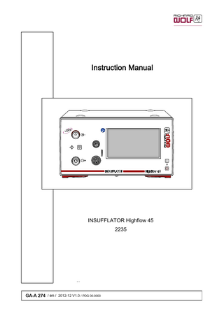
Instruction Manual
56 Pages
Preview
Page 1
Instruction Manual
INSUFFLATOR Highflow 45 2235
GA-A 274 / en / 2012-12 V1.0 / PDG 00-0000
Important general notes and instructions Make sure that this product is used only as intended and described in this instruction manual, by adequately trained and qualified medical personnel, and that maintenance and repair are only carried out by authorized experts. Use the product only in the combinations and with the accessories and spare parts specified in this instruction manual. Use other combinations, accessories and replacement parts only if they are expressly intended for the planned applic ation and if the performance characteristics and safety requirements are not impaired. Do not alter the product in any way. Reprocess the products before every application and before returning them for repairs as required by the instruction manual in order to protect the patient, user and others. This manual is an integral part of the product and must be stored in such a way that it is accessible at any time during its entire life cycle. This manual must be passed on to any subsequent owner. Immediately upon receipt, check the product and its accessories for completeness and possible damage. Should the shipment give right to complaints, please inform the manufacturer or supplier immediately. Subject to technical changes! Due to ongoing developments, the illustrations and technical data may deviate slightly.
Safety instructions and levels of danger Symbols
Level of danger
WARNING!
Failure to observe can result in death or serious injury.
CAUTION!
Failure to observe can result in slight injury or damage to the product.
.
IMPORTANT!
.
NOTE!
Failure to observe can result in damage to the product or surroundings. Tips for optimum use and other useful information.
GERMANY RICHARD WOLF GmbH 75438 Knittlingen Pforzheimerstr. 32 Telephone: +49 70 43 35-0 Telefax: +49 70 43 35-300 MANUFACTURER [email protected] www.richard-wolf.com BELGIUM / NETHERLANDS N.V. Endoscopie RICHARD WOLF Belgium S.A. Industriezone Drongen Landegemstraat 6 9031 Gent Drongen Telephone: +32 92 80 81 00 Telefax: +32 92 82 92 16 [email protected] www.richard-wolf.be Marketing Office U.A.E RICHARD WOLF Middle East P.O. Box 500283 AL Thuraya Tower 1 9th Floor, Room 904, Dubai Telephone: + 9 71 43 68 19 20 Telefax: + 9 71 43 68 61 12 [email protected] www.richard-wolf.com
GA-A 274
USA RICHARD WOLF Medical Instruments Corporation 353 Corporate Woods Parkway Vernon Hills, Illinois 60061 Toll Free: 001 (800) 323 - 9653 Phone: 001 (847) 913 - 1113 Fax: 001 (847) 913 - 1488 [email protected] www.richardwolfusa.com FRANCE RICHARD WOLF France S.A.R.L. Rue Daniel Berger Z.A.C. La Neuvillette F-51100 Reims Telephone: +33 3 26 87 02 89 Telefax: +33 3 26 87 60 33
UK RICHARD WOLF UK Ltd. Waterside Way Wimbledon SW17 0HB Telephone: + 44 20 89 44 74 47 Telefax: + 44 20 89 44 13 11 [email protected] www.richardwolf.uk.com
[email protected] www.richard-wolf.com
AUSTRIA RICHARD WOLF Austria Ges.m.b.H. Wilhelminenstraße 93 a A-1160 Vienna Telephone: +43 14 05 51 51 Telefax: +43 14 05 51 51 45
INDIA RICHARD WOLF India Private Ltd. JMD Pacific Square No. 211 A, Second Floor Behind 32nd Milestone Gurgaon - 122 001 National Capitol Region Telephone: + 91 12 44 31 57 00 Telefax: + 91 12 44 31 57 05 [email protected] www.richard-wolf.com
0
Contents 1 1.1 1.2 1.3 1.4 1.4.1 1.4.2 1.5 1.5.1 1.5.2 1.5.3 1.6 1.7
General information... 1 Symbols... 1 Intended use... 2 Indications and field of use... 3 Contraindications and side effects... 3 Contraindications... 3 Side effects... 5 Combinations... 6 Instruments for INSUFFLATOR Highflow 45... 6 Potential equalization... 7 Requirements for products / components of a combination... 7 Electromagnetic compatibility (EMC)... 8 Connection diagram - in dialog mode (option)... 10
2 2.1 2.2
Illustration... 11 Front view... 11 Rear view... 12
3 3.1 3.2 3.2.1 3.2.2 3.3 3.3.1 3.3.2 3.4 3.4.1 3.4.2 3.4.3
Setup... Language settings... CO2 connection... Preparation for CO2 operation with gas bottle/cylinder... Preparation for CO2 operation using centralized gas supply... Connecting the insufflation tube set... Reprocessable insufflation tubes... Disposable insufflations tube... Highflow insufflation tubes with heating wire... Reprocessable highflow insufflation tube with heating wire... Disposable highflow insufflation tube with heating wire... Disposable tube set for smoke gas evacuation...
13 14 14 14 15 15 16 16 17 17 18 18
4 4.1 4.2 4.2.1 4.2.2 4.2.3 4.2.4
Checks... Visual check... Function check... Device function after switching on the device... Checking the gas supply (status message)... Manual checks of the control function... Checking the pressure and flow control...
19 19 19 19 20 20 20
5 5.1 5.2 5.2.1 5.2.2 5.2.3 5.2.4 5.2.5 5.2.6 5.3
Use... Operating principle... Controls and modes... Operation and display... Dispaly of remaining CO2 gas supply in the status display... Gas consumption in status display... Indicator for gas heating (only 2235021, 2235031 / 2235621, 2235631)... Footswitch for smoke gas evacuation (option)... Video on-screen display with dialog function (option)... Control sequence and menu structure...
22 22 22 22 22 22 23 23 23 24
GA-A 274
I
5.3.1 5.3.2 5.4 5.5 5.6 5.7 5.8 5.8.1 5.9 5.10 5.10.1 5.11 5.11.1 5.11.2 5.12 5.12.1 5.12.2 5.12.3 5.12.4 5.12.5 5.12.6 5.12.7 5.12.8 5.13 5.13.1 5.13.2 5.13.3 5.13.4 5.13.5 5.13.6 5.13.7
Overview - control sequence... 24 Overview - menu structure... 25 Menu levels... 26 Menu control and touchscreen functions... 26 Selection of main level... 27 Selection of device modes... 28 Selection of Richard Wolf profiles... 28 Changing the standard profiles (default profiles)... 28 Profiles... 29 Device parameters... 31 Adjusting the device parameters... 31 Display of actual and nominal values... 32 Service... 33 General service... 33 Operation of INSUFFLATOR Highflow 45... 34 Important note for using the reprocessable highflow insufflation tube with heating wire 34 Notes and instruction for using smoke gas evacuation... 35 Creating a pneumoperitoneum... 35 Highflow device mode... 35 Measures after carrying out insufflation... 36 Possible alarms during the application... 36 Power failure... 36 Taking out of service... 36 Overview of operator messages... 37 Structure of operator messages... 37 Message types... 37 Functionality of control elements... 37 Operator's messages (green)... 38 LOW error (turqoise)... 38 MEDIUM error (yellow)... 40 HIGH error (red)... 40
6 6.1 6.2 6.3 6.4
Operation within the core system... Functional principle within the core system... Combining and controlling the device... Setting the system ID... Connection to the core system...
41 41 41 41 42
7 7.1 7.2 7.2.1 7.2.2 7.3 7.4 7.4.1 7.5 7.5.1 7.5.2
Reprocessing and maintenance... Reprocessing of device... Reprocessing of reusable insufflation tubes... Cleaning... Sterilization... Reprocessing of reusable highflow insufflation tube with heating wire... Maintenance... Maintenance intervals... Quarterly check... Measuring and test equipment... Checking the pressure and flow control...
43 43 43 44 44 44 44 44 44 44 45
II
GA-A 274
Contents 7.5.3
Leakage test... 45
8 8.1 8.1.1 8.2 8.2.1 8.2.2 8.2.3 8.2.4 8.3 8.4 8.5 8.5.1 8.5.2
Technical description... Troubleshooting... Fault in the core system... Technical data... Application parameters... Pressure and flow values... Interfaces... Optional device variants... Operating, storage, transport and shipping... Spare parts and accessories... Replacing parts... Device fuses... Disposal of product, packaging material and accessories...
GA-A 274
46 46 46 47 47 48 48 49 49 50 51 51 51
III
1
General information
1.1
Symbols Symbols
Designation Attention, Caution Follow the instruction manual OFF (no power supply, separation from mains) ON (connection to the mains / line voltage) Potential equalization Power / Mains fuse
μ
Alternating current (AC) TYPE CF APPLIED PART Hygiene filter Gas heating Alarm Signal sound Signal sound switched off Footswitch Input connector for smoke gas evacuation / data input Output connector for insufflation / data output Recycle the product separately. Do not discard together with other waste.
REF
Order number Lot designation Manufacturer Manufacturing date Quantity Use-by date
1
GA-A 274
Symbols
Designation Do not reuse. Latex-free Contains phthalates or phthalates are present: Diethylhexyl phthalate (DEHP)
-25_C
Maximum temperature range for shipment, transport and storage
+ 50_C
Sterilized with ethylen oxide Steam sterilization - fractional method XX° XX°
Permissible temperature range
XXhPa
Permissible atmospheric pressure range XXhPa XX%
Permissible humidity range XX%
Do not use mobile phone / radio intercom A Registered Trademark of a Recognized Testing Laboratory, confirm the compliance to the standard of Medical Electrical Equipment CAN/CSA C22.2 No.60601-1 (c) and ANSI/AAMI ES60601-1 (us) Identification in conformity with medical devices directive 93/42/EEC only valid if the product and/or packaging is marked with this symbol. Products of category IIa and above, as well as sterile products or products with measuring function of category I, are additionally identified with the code no. of the notified body (0124).
1.2
Intended use The INSUFFLATOR Highflow 45 (2235) serves to create and maintain a pneumoperitoneum using CO2 gas. It can be used for both diagnostic and surgical laparoscopy. In conjunction with integrated smoke gas evacuation (2235011/2235031) and the "Continuous Flow" (2235104) software module, the system also serves to distend the colon (rectal cavity and lower portion of the sigmoid) in a pressure-controlled manner for the purpose of Transanal Endoscopic Microsurgery (TEM). This product is designed exclusively for use by specialized medical per sonnel and may only be applied by medically qualified and adequately trained doctors.
GA-A 274
2
1.3
Indications and field of use The INSUFFLATOR Highflow 45 (2235) is primarily used in diagnostic and surgical laparoscopy but can also be used for TEM using the integ rated smoke gas evacuation (2235011/2235031) and the "Continuous Flow" (2235104) software module. For TEM applications please follow the latest instruction manual for the TEM system. On the basis of the patient’s general condition, the user in charge must decide whether the planned use is possible or not. For further notes and instructions please refer to the latest medical literature.
CAUTION! In case of therapeutic applications an adequate backup device with the same capabilities must be available should the device fail. CAUTION! It is not allowed to use mobile phones or similar devices while the INSUF FLATOR Highflow 45 is used.
.
NOTE! We recommend reading relevant literature for the planned application.
1.4
Contraindications and side effects
1.4.1
Contraindications
The use of this device is contraindicated whenever laparoscopy is con traindicated.
WARNING! The device has a highflow rate. The device is not suitable for hysteroscopy. This device must not be used for distending the cavum uteri. Contraindications resulting from the patient's general condition and de scribed in the relevant literature must be observed. This device is contraindicated in the case of hysteroscopic insufflation do not use this device for intrauterine distension. Absolute contraindications: D Hypovolemic shock represents an absolute contraindication with the exception of laparoscopic surgeons who have adequate experience in procedures for blood extraction from the abdomen and for finding and stopping a hemorrhage site and can execute them safely and so can achieve hemostasis quicker than by laparotomy. D In the case of severe inflation of the intestine during intestinal obstruc tion, increased possibility of adhesions in the pelvis and in the abdomen as well as in the case of an elevated diaphragm, the required insuf flation is contraindicated and the space available for a visualization is severely limited and the probability of injuring the intestine is severely increased. D A further contraindication is the existence of a large mass in the pelvis or in the area of the pelvis and abdomen (which in general extends to the umbilicus or above). There is an increased risk of injuring this mass, and there is a high probability that endoscopic visualization is poor and that the extension and the nature of the mass cannot be determined. A mass of this size would probably have to be removed by a laparotomy.
3
GA-A 274
D A type 4 cardiac decompensation also represents a contraindication as the insufflation and its positioning could cause irreversible arrhythmia to the heart which is filled with congested blood and cause cardiac failure. Relative contraindications: D Septic peritonitis D Pelvic abscess D Multiple interventions in the abdomen D Diaphragmatic hernia D Obesity D Pregnancy TEM is contraindicated where a general contraindication against surgical interventions, a severe infection or severe metabolic disorders exist. On the basis of the patient's general condition the doctor in charge must decide whether the planned use is possible or not. For further notes and instructions please refer to the latest medical literature.
GA-A 274
4
1.4.2
Side effects
Warnings: Metabolic acidosis and the resulting cardiac arrhythmia. Intraabdominal pressures of more than 20 mmHg (mercury column) for an extended period of time must be avoided. This may lead to the following complications: D Reduced breathing with impaired diaphragm excursion D Reduced venous backflow D Reduced cardiac output D Acidosis Excessive absorption of CO2 is either due to excessive flow or excessive pressure. The abdomen can be sufficiently distended with pressures between 15 - 20 mmHg (mercury column). Hardly ever abdominal pres sures of more than 20 mmHg are required. At these values only limited absorption should occur. Pressures of more than 20 mmHg (mercury column) are actually never necessary and will lead to increased and faster absorption. Adequate artificial respiration will help to avoid prob lems with regard to CO2. Z Idiosyncratic reactions. In patients suffering from sickle-cell disease or pulmonary insufficience the use of these devices can lead to an in creased risk of a metabolic imbalance due to excessive CO2 absorp tion. Z Hypothermia. Highflow rates bear the potential risk of hypothermia. Precautions: It is strongly recommended using a hydrophobic bacteria filter to prevent the transmission of microorganisms between patients.
5
GA-A 274
1.5
Combinations
.
IMPORTANT! In addition to this instruction manual, follow the manuals for the products used in combination with this product. WARNING! Danger of life-threatening gas or air embolism. Purge the connection tubes/hoses with a sufficient amount of CO2 before use. The use of devices using additional gaseous media in combination with the INSUFFLATOR Highflow 45 is exclusively within the responsibility of the user. WARNING! Danger of intrabdominal excess pressure when using a second gas source. When using argon plasma coagulators an additional visual or manual pressure monitoring device of the user is mandatory because the pressure monitoring function / pressure relief of the INSUFFLATOR High flow 45 can be inactive as a result of a kinked insufflation tube or a closed instrument stopcock. The preselected gas flow rates of the argon plasma coagulator should not exceed 2 l/min. Activate the argon plasma coagulator only briefly.
1.5.1
Instruments for INSUFFLATOR Highflow 45 The INSUFFLATOR Highflow 45 can be combined with the instruments used during a diagnostic and/or surgical laparoscopy and/or TEM. Follow the instruction manuals of the products used in conjunction with this product. On principle, the INSUFFLATOR Highflow 45 can be combined with all trocar sleeves available in the market.
GA-A 274
6
1.5.2
Potential equalization The potential equalization cable establishes a direct connection between a medical electrical de vice and an equipotential bonding rail. It serves to equalize differences in potential between enclosures of electrical equipment and firmly installed conductive parts in the patient environment.
1.5.3
Requirements for products / components of a combination 1.5m
1.5m The general requirements depend on whether the products / components are inside or outside the patient environment.
1.5m
IEC 60601-1, 3. Ed.
Medically used room inside the patient environment MP
MP
~
~
MP
MP
~
NMP
~
~
MP
NMP
MP
Non-medically used room
-
-
Requirements / measures Leakage currents to section 16.6 IEC 60601-1:2005 / EN 60601-1:2006 *
Verification of the total patient leakage current
**
MP
~
outside the patient environment
**
-
Verification of leakage currents
**
a) additional protective earth connection (consult the corresponding manufacturer),
-
or
NMP
b) additional isolating transformer for medical applications **
~ MP
NMP
~ MP / NMP
MP
~
**
MP
NMP
~
~
MP
MP / NMP
~
~
additional "isolating transformer" to IEC/ EN60601-1 ** Functional connection MP NMP
Verification of leakage currents a) no plugs with metal housing, or b) additional isolation device (to avoid voltage differentials)
-
~
Verification of leakage currents a) common protective earth connection, or b) additional protective earth connection at MP (clarify with the corre ponding manufacturer), or c) additional isolation device (to avoid voltage differentials), or d) no plugs with metal housing in the patient environment
additional isolating device to IEC/ EN 60601-1
Multiple socket strip
Power supply grid
= medical electrical device to IEC/ EN 60601-1, ANSI/AAMI es60601-1, CSA C22.2 No. 60601-1 08 = non-medical electrical device in accordance with product-specific IEC/EN/UL standards
* **
When connected via a multiple socket strip under standard conditions the earth leakage current of the power bar must not exceed 5 mA. e.g. Richard Wolf video cart with "isolating transformer"
7
GA-A 274
.
1.6
IMPORTANT! The persons combining products to form a system are responsible for not impairing the system's compliance with performance and safety requirements, and that the technical data and the intended use are adequately fulfilled. Possible electromagnetic or other interference that may occur between the product and other products can cause faults or malfunctions. When selecting the system components, make sure that they meet the necessary requirements of the medical envi ronment they are used in, in particular IEC/ EN 60601-1 (3. Edition IEC/EN 60601-1, section 16). In case of doubt contact the manufacturer(s) of the system components. Do not touch connectors for electrical connections between various components (such as signal input connectors and signal output connectors for video signals, data exchange, controls etc.) and the patient at the same time.
Electromagnetic compatibility (EMC)
Please observe the following: The device/system in the following referred to as product always related to INSUFFLATOR Highflow 45. The product does not have any performance features classified as essential performance features in accordance with IEC/EN 60601-1.
Guidelines and manufacturer's declaration - Electromagnetic emissions The product is intended for use in the environment specified below. The user must assure that the product is used in such an environment. Emissions measurement / test
Compliance
Electromagnetic environment - Guidelines
HF emissions to CISPR 11
Group 1
The product uses HF energy for its internal function. The HF emission level is extremely low and it is not likely to cause any interference in nearby electronic equipment.
HF emissions to CISPR 11
Class B
Harmonic emissions to IEC 61000-3-2
Class A
In conformity with IEC 61000-3-3 “Emission of voltage fluctuations / flicker"
The product is suitable for use in all establishments, including domestic establishments. This also includes establishments directly connected to the public low voltage power supply network that supplies buildings used for domestic purposes.
Guidelines and manufacturer's declaration - Electromagnetic immunity The product is intended for use in the environment specified below. The user must assure that the product is used in such an environment. Compliance
Immunity tests
IEC 60601 test level
Electromagnetic environment - Guidelines
Electrostatic discharge (ESD) to IEC 61000-4-2
6 KV contact discharge 8 KV air discharge
Yes
Floors should be wood, concrete or ceramic tile. With floors made of synthetic material, the relative humidity of the ambient air must be at least 30%.
Electrical fast transience, bursts to IEC 61000-4-4
2 KV for power supply lines 1 KV for input and output lines
Yes
Mains/line power quality should be that of a typical commercial or hospital environment.
Surge voltage (surges) to IEC 61000-4-5
1 KV line to line voltage 2 KV line to ground voltage
Yes
Mains/line power quality should be that of a typical commercial or hospital environment.
Voltage dips, short interruptions and sup ply voltage variations to IEC 61000-4-11
Voltage dip for 0.5 cycle > 95% UT * Voltage dip for 5 cycles 60% UT * Voltage dip for 25 cycles 30% UT * Voltage dip for 5 sec > 95% UT *
Yes
Mains/line power quality should be that of a typical commercial or hospital environment. If the user of the product requires continued operation during power mains/line interruptions it is recommended that the product be powered from an uninterrupti ble power supply or battery.
Power frequency (50/60 Hz) magnetic field, to IEC 61000-4-8
3 A/m
Yes
Power frequency magnetic fields should be at le vels characteristic of a typical location in a com mercial or hospital environment.
* NOTE: UT is the line / mains voltage prior to application of the test level.
GA-A 274
8
Guidelines and manufacturer's declaration - Electromagnetic immunity for products that are not life-supporting The product is intended for use in the environment specified below. The user must assure that the product is used in such an environment. Immunity tests
IEC 60601 test level
Compliance
Electromagnetic environment - Guidelines Portable and mobile RF communications equipment should be used no closer to any part of the product, including ca bles, than the recommended separation distance calculated from equation applicable to the frequency of the transmitter. Recommended separation distance: d = 1.2 p P
Conducted HF interference to IEC 61000-4-6
3 Vrms 150 kHz to 80 MHz
Radiated HF interference to IEC 61000-4-3
3 V/m 80 MHz to 2.5 GHz
d = 1.2 p P for 80 MHz to 800 MHz Yes
d = 2.3 p P for 800 MHz to 2.5 GHz P = Nominal power output rating of the transmitter in watts (W) (according to the transmitter manufacturer)
d = recommended separation distance in meters (m) Field strengths from fixed RF transmitters, as determined by an electromagnetic site survey1, should be less than the compliance level in each frequency range2. Interference may occur in the vicinity of devices with the following symbol:
REMARKS: At 80 MHz and 800 MHz the higher frequency range applies. These guidelines may not apply in all situations. The propagation of elec tromagnetic waves is affected by absorption and reflexion from buildings, objects and people. 1 = The field strength of stationary transmitters (e.g. base station for radio phone, earth to earth radio stations,, amateur radio stations, radio and television transmitters) cannot be exactly predicted in theory. To assess the EMC environment due to fixed transmitters an electromagnetic site survey should be conducted. If the measured field strength in the location in which the product is used exceeds the applicable compliance level above, the product should be observed to verify normal operation. If abnormal performance is observed, additional measures may be required, such as reorienting or relocating the product. 2 = Over the frequency range between 150 kHz and 80 MHz the field strength should be below 3 V/m.
Recommended separation distances between portable and mobile HF telecommunication devices and devices which are not life-supporting The product is intended for use in an electromagnetic environment where HF disturbances are controlled. The user can help prevent electromagnetic interference by maintaining a minimum distance between portable and mobile HF telecommunica tions equipment and the product. Rated nominal output power of the transmitter (W)
Separation distance as a function of transmitter frequency (m) 150 kHz to 80 MHz d = 1.2 p P
80 MHz to 800 MHz d = 1.2 p P
800 MHz to 2.5 GHz d = 2.3 p P
0.01
0.12
0.12
0.23
0.1
0.38
0.38
0.73
1
1.2
1.2
2.3
10
3.8
3.8
7.3
100
12
12
23
For transmitters rated at a nominal output power not listed in the table above, the recommended separation distance (d) in meters (m) can be determined using the applicable equation (observe frequency). P = nominal power of the transmitter in Watts (W). REMARKS: At 80 MHz and 800 MHz the higher frequency range applies. These guidelines may not apply in all situations. The propagation of elec tromagnetic waves is affected by absorption and reflexion from buildings, objects and people.
9
GA-A 274
1.7
Connection diagram - in dialog mode (option)
1.1
1.1
1
2
Legend Direct connection 1
CAN BUS connection cable (option)
1.1
CAN BUS termination (option)
2
Video cable to meet the signal requirements of the camera controller used
.
IMPORTANT! The optional dialog function is only possible is only possible with enabled software module 3 of INSUF FLATOR Highflow 45.
Connection of the CAN BUS connection cable (1) only with interactive camera controller.
If the CAN BUS connection cable is connected, the free CAN BUS connectors of INSUFFLATOR Highflow 45 and the camera controller must be terminated with CAN BUS terminating resistors (1.1).
GA-A 274
10
2
Illustration
2.1
Front view
6
5
4
3
2
1.1
1
Legend 1
Power ON/OFF switch
1.1
Power ON/OFF LED
2
Touchscreen
3
Connector for disposable highflow insufflation tube with heating wire ' only 2235021, 2235031 / 2235621, 2235631
4
Connector for reusable highflow insufflation tube with heating wire ' only 2235021, 2235031 / 2235621, 2235631
5
Connector for insufflation tube (type CF applied part)
6
Connector for smoke gas evacuation (type CF applied part) ' only 2235011, 2235031 / 2235611, 2235631
11
GA-A 274
2.2
Rear view 13
14
12 15
11
10
8
7
9 16 FEDERAL LAW RESTRICTS THIS UNIT TO BE USED OR SOLD, EXCEPT UNDER THE SUPERVISION OF A MEDICAL DOCTOR.
Legend 7
Potential equalization connector
8
Connector for footswitch for smoke gas evacuation ' only 2235011, 2235031 / 2235611, 2235631
9
Service interface
10
Silencer ' only 2235011, 2235031 / 2235611, 2235631
11
Power input connector with fuse holder
12
Fuse plate
13
Device connector for gas supply
14
CAN BUS interface
15
Mounting points for bottle holding bracket
16
Identification plate
GA-A 274
12
3
Setup WARNING! The device is not protected against explosions. Explosion hazard. Do not operate this device in areas where there is a danger of explosion. WARNING! Danger if a power supply without protective earth is used. Danger of electric shock! Connect the device only to a power supply with protective earth connec tor.
.
NOTE! The line / mains voltage must correspond with the voltage indicated on the identification plate. Connect the device only via the supplied power cable or a power cable with the same specifications. Do not block any ventilation slots! CAUTION! Danger of faults and malfunctions. To guarantee the safety of the user, patient and others, use only acces sories and spare parts as specified by the manufacturer of this product. Other accessories or spare parts can cause the emission of increased electromagnetic radiation or reduced immunity against interference.
.
IMPORTANT! Medical electrical equipment is subject to special precautions with regard to electromagnetic compatibility (EMC). Make sure you follow the notes on EMC for installation and operation. Medical electrical devices can be influenced by mobile HF communication devices. If it is necessary to stack the devices or place them next to each other and HF interference is observed, make sure that the devices are ope rated as specified in the intended use. WARNING! Use the device only with the insufflation tubes and filters specified by the manufacturer. Sterilize the insufflation tube before each use. Danger of infection due to unsterile accessories and possible malfunction (loss of gas pressure or gas flow) when using spare parts supplied by other manufacturers or in the case of wrong assembly. CAUTION! Disposable items have been designed for one single use only and are sterilely packed. Do not use disposable items if: ' the sterile packaging is damaged ' the use-by-date has been exceeded
13
.
NOTE! For use, place the device on a level surface.
.
NOTE! Remove the protective foil from the touchscreen before the first use.
GA-A 274
3.1
Language settings
Fig. 1
The language is selected in the Device parameters menu (see section 5). When switching on the device for the first time (setup) as well as during a new start after having reset the device to "factory settings", the required language must be selected. ' Language selection for the “Standard profile”. ' For "User-specific operator profile" it is possible to define a separate language. If a wrong language was selected and it is impossible to select the language selection menu in this language, proceed as follows: Z Switch off the device and wait for at least 60 seconds. Z Switch on the device and press the device name on the touchscreen until the language selection menu is displayed. Z Let go of the button and select the required language. ' Language selection for the “Standard profile”.
3.2
CO2 connection
3.2.1
Preparation for CO2 operation with gas bottle/cylinder
WARNING! Make sure that no liquid CO2 enters the INSUFFLATOR Highflow 45 as a result of incorrect positioning of the gas bottle/cylinder! This will endanger the patient as a result of possible malfunctions or fail ure of the INSUFFLATOR Highflow 45 during the surgical intervention. Operate the gas bottle/cylinder only in vertical position with the valve on top.
.
18
Z Use mounting screws (15) to attach the bottle holding bracket (18) to the device if required ' Optionally, large gas bottles/cylinders can be fastened to a device cart.
15
.
GA-A 274
IMPORTANT! Observe the manual for the pressure reducing valve.
IMPORTANT! When using gas bottles with more than 2 l of volume, use a separate holding bracket (do not attach to the INSUFFLATOR Highflow 45) and secure the gas bottle/cylinder against falling over.
14
Z Place the gas bottle (max. 2 l of volume) into the bottle holding bracket and secure with the belt (18.1).
18.1
20.1
20
19.1
Z Connect the pressure reducing valve (20) to the gas bottle (19) and tighten the union nut (20.1) with your hand.
19
Z Connect the CO2 pressure tube (21) to the pressure reducing valve (20) and tighten the union nut (21.1) with your hand.
21.1
Z Open the bottle valve (19.1) by turning counterclockwise.
21
3.2.2
Preparation for CO2 operation using centralized gas supply
Connection to a centralized gas supply 17.1
Z Connect the CO2 pressure tube (17) to the device connector for gas supply and hand-tighten the union nut (17.1). ' Then connect the CO2 pressure tube (17) to the wall connector for centralized gas supply.
17
3.3
Connecting the insufflation tube set CAUTION! Contamination of the device by a backflow of gas or body fluid. There must always be a hygiene filter between the device connector and the insufflation tube.
.
15
IMPORTANT! To connect and disconnect the insufflation tube always hold it by the con nectors.
GA-A 274