Technical Documentation
224 Pages
Preview
Page 1
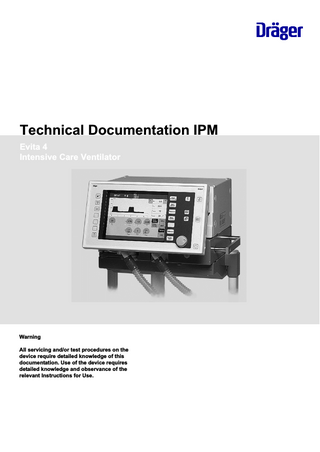
Technical Documentation IPM Evita 4 Intensive Care Ventilator
Warning All servicing and/or test procedures on the device require detailed knowledge of this documentation. Use of the device requires detailed knowledge and observance of the relevant Instructions for Use.
No.2106_0000002233-005
This page intentionally left blank.
2
Evita 4
Technical Documentation IPM
Table of contents
Table of contents 5 6 9 10 11 12 13 15 18 22 27 28 30 32 33 35 40 41 61 63 65
No.2106_0000002233-005
General 1 General notes ... Abbreviations 1 List of abbreviations and glossary of terms ... Function descriptions 1 General information ... 2 Basic principle ... 3 CPU 68332 PCB... 4 CO2 Carrier PCB ... 5 CO2 measurement... 6 Power supply unit ... 7 Evita 4 Graphics Controller PCB ... 8 Communication PCB (option) ... 9 Paediatric Flow PCB (optional)... 10 IFCO Carrier PCB (optional nurse call and other) ... 11 Pneumatic Controller PCB... 12 HPSV Controller PCB... 13 Pneumatic assembly ... 14 Gas mixture ... 15 Pneumatics function diagram ... Annex
Technical Documentation IPM
Evita 4
3
No.2106_0000002233-005
This page intentionally left blank.
4
Evita 4
Technical Documentation IPM
General
This chapter contains general notes and definitions that are important for the use of this documentation.
General notes ...
6
No.2106_0000002233-005
1
Technical Documentation IPM
Evita 4
5
General General notes
1
General notes
1.1
Notes on use Read through the following notes thoroughly before applying this documentation. Dräger reserves the right to make changes to the device and/or to this documentation without prior notice. This documentation is intended solely as an information resource for maintenance personnel or technical specialists.
1.2
Copyright and other protected rights The content of this documentation, in particular its design, text, software, technical drawings, configurations, graphics, images, data and their selection and its composition and any amendments to it (content) are protected by copyright. The content must not (in whole or in part) be modified, copied, distributed, reproduced, republished, displayed, transmitted or sold without the prior written consent of Dräger.
1.3
Definitions WARNING An important advisory indicating a potentially hazardous situation which may result in death or serious injury if not prevented. CAUTION An important advisory indicating a potentially hazardous situation which may result in minor or moderate injury to the user or patient or in damage to the medical product or other assets if not prevented. NOTE A NOTE provides additional information intended to avoid inconvenience during operation and/or servicing. Term
Definition Maintaining the operative condition of a medical product by suitable means
Inspection
Assessment of the actual condition of a medical product
Servicing
Maintaining the operative condition of a medical product by recurrent, specified measures
Repair
Restoring the operative condition of a medical product after failure of a device function
No.2106_0000002233-005
Maintenance
6
Evita 4
Technical Documentation IPM
General General notes
1.4
General safety precautions Read through each section thoroughly before beginning servicing. Always use the correct tools and the specified test equipment. Otherwise the device may not work correctly or may be damaged. WARNING The device must be regularly inspected and serviced by maintenance personnel. Repairs and complex maintenance work on the medical product must be carried out by qualified specialists. If you require a service contract, or for any necessary repair work, Dräger recommends DrägerService. Dräger recommends using original Dräger parts for servicing. If the aforementioned instructions and recommendations are ignored, the correct functioning of the medical product may be put at risk. Pay attention to the "Servicing" section of the Instructions for Use. WARNING Non-conforming test values If test values do not conform to specifications, the safety of the patient may be put at risk. –
Do not put the device into operation if test values do not conform to specifications.
–
Contact your local service organization.
WARNING Impermissible modifications to the device If impermissible modifications are made to the device, the safety of the patient may be put at risk. Do not modify the device without Dräger's permission. WARNING Risk of infection The unit may transmit pathogens following use on the patient. –
Before carrying out any servicing, ensure that the device and its components have been handed over by the user cleaned and disinfected.
–
Service only cleaned and disinfected units and unit components.
WARNING Risk to patient. Ensure that no patient is connected to the device before starting maintenance or repair work. NOTE
No.2106_0000002233-005
Where reference is made to legislation, regulations and standards, in respect of devices used and serviced in Germany they are based on the laws of Germany. Users and technicians in other countries must comply with their national laws and/or international standards.
Technical Documentation IPM
Evita 4
7
No.2106_0000002233-005
This page intentionally left blank.
8
Evita 4
Technical Documentation IPM
Abbreviations
This section contains a list of the abbreviations used in this document.
List of abbreviations and glossary of terms ...
10
No.2106_0000002233-005
1
Technical Documentation IPM
Evita 4
9
Abbreviations List of abbreviations and glossary of terms
1
List of abbreviations and glossary of terms Abbreviation
Term Automatic Tube Compensation
BTPS
Measured values referring to conditions of the patient's lung, body temperature 37 °C, water vapour saturated gas, ambient pressure (Body Temperature, Pressure Saturated)
CAN
Fast serial port (Controller Area Network)
COM
Serial port
DUART
Dual Universal Asynchronous Receiver/Transmitter
EGB
Electrostatic sensitive devices
ECG-SYNC
ECG Synchronization
ESD
Electrostatic Sensitive Device
FiO2
Inspiratory O2 concentration
HPSV
High Pressure Servo Valve
ILV
Independent Lung Ventilation
NIF
Negative Inspiratory Force
NIV
Application mode for support of non-invasive ventilation therapies
NTPD
Normal Temperature, Pressure Dry
Paw
Airway pressure
PIP
Peak Inspiratory Pressure
RSB
Rapid Shallow Breathing (quotient of spontaneous breathing frequency and breathing volume)
SpO2
Functional oxygen saturation
VTASB
Tidal volume ASB
No.2106_0000002233-005
ATC
10
Evita 4
Technical Documentation IPM
Function descriptions
This chapter contains descriptions of the device's technical functions.
General information ... Basic principle ... CPU 68332 PCB... CO2 Carrier PCB ... CO2 measurement... Power supply unit ... Evita 4 Graphics Controller PCB ... Communication PCB (option) ... Paediatric Flow PCB (optional)... IFCO Carrier PCB (optional nurse call and other) ... Pneumatic Controller PCB... HPSV Controller PCB... Pneumatic assembly ... Gas mixture ... Pneumatics function diagram ...
12 13 15 18 22 27 28 30 32 33 35 40 41 61 63
No.2106_0000002233-005
1 2 3 4 5 6 7 8 9 10 11 12 13 14 15
Technical Documentation IPM
Evita 4
11
Function descriptions General information
1
General information The Evita 4/ Evita 4 edition is a time-cycled, constant-volume long-term ventilator for adults and children. The features and ventilation modes depend on the specific device and its optional features; they are described in the Instructions for Use of the specific device.
1.1
Evita 4 edition New design: –
The background foil is gray.
–
The alarm silence key is yellow.
–
The back of the display housing is blue.
New default option - "SW 4.0 Plus": –
Weaning parameters RSBi, NIF and VTASB.
–
Measurement of an external flow source.
–
Large loops.
New software version SW 4.20: –
Extended alarm management for battery, flow sensor and MediBus.
–
Optimized ATC®, NIV and NeoFlow.
By the integrated "Software 4.0. Plus" option loops can be displayed in fullscreen format. A cursor can be used to determine individual values in the loop sequence. This facilitates an accurate examination of the lung mechanics. Rapid shallow breathing index, negative inspiratory force index and VTASB contribute to an improved weaning process. Optional features such as ATC®, PPS, NIV and NeoFlow can be added.
No.2106_0000002233-005
Evita 4 edition offers both conventional and non-invasive ventilation. Due to its new type of dynamic leakage compensation, the Evita 4 edition is ready to meet mask ventilation requirements.
12
Evita 4
Technical Documentation IPM
Function descriptions Basic principle
2
Basic principle
2.1
Evita 4 The Evita 4 consists of three components which communicate via a CAN (fast serial interface). Control unit (Fig. 1/1)
–
Electronics (Fig. 12)
–
Pneumatics (Fig. 1/3)
4418
–
Fig. 1
Basic components of the Evita 4
Control unit
The control unit is the interface between the device and the operator. The control unit serves to make adjustments, to display measured values and to generate alarms. In the control unit the display, keypad, touch-screen and Graphics Controller PCB are accommodated.
2.1.2
Electronic assembly
The electronics is the central control unit of the Evita 4. The electronics includes the CPU 68332 PCB, the CO2 Carrier PCB with the Processor Board PCB and the Power Supply PCB and the power supply unit (Communication PCB, Paediatric Flow PCB, IFCO PCB and the SpO2 PCB as option).
No.2106_0000002233-005
2.1.1
Technical Documentation IPM
Evita 4
13
Function descriptions Basic principle
Pneumatic assembly
The pneumatic assembly controls the pneumatic valves following preset ventilation parameters. It includes an independent microprocessor system and the valve control. In the pneumatics the Pneumatics Controller PCB, the HPSV Controller AIR/O2 PCB, the PEEP valve, the mixer, the pressure connection, the flow sensor and the O2 sensor are accommodated.
2.2
Simplified block diagram of the Evita 4
4420
2.1.3
Fig. 2
Basic principle of the Evita 4
Item
Designation
Item
Designation
Front panel.
12
Battery (Goldcap capacitor).
B
Electronics.
13
Supply voltages.
C
Pneumatics.
14
Power switch.
1
Keys.
15
Second inspiratory Paw sensor.
2
Control knob (press to confirm).
16
Pneumatics processor and venting reset.
3
Touchscreen.
17
Electronic processor reset and second loudspeaker alarm.
4
TFT display 640 x 480.
18
Inspiratory Paw sensor.
5
Information LEDs and Alarm LEDs.
19
O2 sensor.
6
CAN bus.
20
FiO2 (HPSV mixer).
7
Graphics processor reset.
21
AIR (HPSV mixer).
8
N/A.
22
Flow sensor.
9
Loudspeaker with sound chip.
23
Expiratory valve with PEEP.
10
Second loudspeaker (piezo).
24
Expiratory Paw sensor.
11
Voltage monitoring (activates reset of the processors and the piezo).
-
14
Evita 4
No.2106_0000002233-005
A
Technical Documentation IPM
Function descriptions CPU 68332 PCB
3
CPU 68332 PCB
4434
The CPU 68332 PCB is located in the electronic assembly of the Evita 4. The board includes an independent processor system, two external interfaces, three internal interfaces, the loudspeaker control and a serial EEPROM.
Fig. 3
3.1
Block diagram CPU 68332 PCB
EEPROM
No.2106_0000002233-005
The EEPROM is connected to the synchronized, serial interface of the 68332. The EEPROM characterizes the Evita 4 (enabled options, serial number, etc.).
Technical Documentation IPM
Evita 4
15
Function descriptions CPU 68332 PCB
3.2
Processor system The processor system comprises a 68332 CPU, a 512 kByte RAM and a 1 MByte flash EPROM (electrically programmable and erasable read-only memory). The RAM has a battery back-up. When the battery is being replaced a Goldcap capacitor ensures voltage supply of the RAMs.
3.3
RS232 interface The CPU 68332 PCB provides an RS232 interface in the device. The interface is labeled COM1. The interface is electrically isolated from the device. Electrical isolation is made by means of optocouplers.
3.4
ILV interface The ILV interface is required for independent-lung ventilation with units. The ILV interface is not electrically isolated. Pin 3 of the ILV interface is provided with a filler plug. This filler plug prevents confusion with the RS232 interface.
3.5
Driver The driver adjusts the access times between the 68332, the clock and the DUART (Dual Universal Asynchronous Receiver/Transmitter).
3.6
Clock The clock gives the current time. When the device is off, the clock runs on battery back-up.
3.7
DUART The DUART has two serial interfaces and digital inputs and outputs. The serial ports are used to connect the SpO2 module and the CO2 module.
3.8
DC/DC converter The DC/DC converter provides the voltage supply (+5 V ISO) required for the interface. The input voltage of the DC/DC converter is +5 V.
3.9
CAN The CAN interface is a fast, serial interface (Controller Area Network). The control unit, the electronics and the pneumatics communicate via a CAN interface. The transmission rate is 800 kbit/s.
Bus driver The address bus, the data bus and the check-back signals are transferred by the bus driver to the motherboard. The 68332 CPU communicates with the optional PCBs on the motherboard via the bus driver. Currently, it is only the Paediatric Flow PCB (NeoFlow option).
16
Evita 4
Technical Documentation IPM
No.2106_0000002233-005
3.10
Function descriptions CPU 68332 PCB
3.11
Sound generator The sound generator controls the loudspeaker in the control unit. The sound generator incorporates the volume control and sound generation for the loudspeaker. The volume is controlled by the DUART.
3.12
Reset logic
No.2106_0000002233-005
The CPU 68332 can reset the control unit and the pneumatics. A reset is also triggered if there is an undervoltage or overvoltage of the +5 V voltage. The pneumatics can also reset the CPU 68332 PCB. The reset logic controls and displays the resets.
Technical Documentation IPM
Evita 4
17
Function descriptions CO2 Carrier PCB
4
CO2 Carrier PCB
4435
The CO2 Carrier PCB is integrated in the electronic assembly of the device. The PCB includes the mount and the electrical isolation of the CO2 module and the SpO2 module, the power failure logic, the temperature measurement and the voltage monitoring.
Block diagram of the CO2 Carrier PCB
No.2106_0000002233-005
Fig. 4
18
Evita 4
Technical Documentation IPM
Function descriptions
4436
CO2 Carrier PCB
CO2 Carrier PCB block diagram, (part 1)
No.2106_0000002233-005
Fig. 5
Technical Documentation IPM
Evita 4
19
Function descriptions
4437
CO2 Carrier PCB
Fig. 6
4.1
CO2 Carrier PCB block diagram, (part 2)
Electrical isolation Electrical isolation is made by means of optocouplers. The PCB is coupled with the SpO2 and CO2 modules by plug-in contacts. The X3 connector is part of the optional SpO2 module and is not fitted.
Power failure logic The power failure logic monitors the power supply. In the event that a mains voltage failure occurs while the device is operating an audible alarm will sound.
20
Evita 4
Technical Documentation IPM
No.2106_0000002233-005
4.2