Stryker
Beds, Chairs, Stretchers and Stools
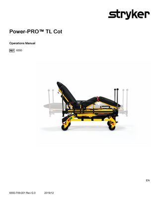
Power-PRO TL Cot Ref 6550 Operations Manual Rev G.0 Dec 2019
Operations Manual
74 Pages
Preview
Page 1
Power-PRO™ TL Cot Operations Manual 6550
EN
6550-709-001 Rev G.0
2019/12
Symbols Refer to instruction manual/booklet
Operating instructions CE mark Authorized representative in the European Community European medical device
General warning
Caution Warning; crushing of hands Warning; non-ionizing radiation No pushing
Do not lubricate Catalogue number Lot (batch) code
Serial number For US Patents see www.stryker.com/patents Manufacturer Date of manufacture Mass of equipment with safe working load Safe working load Type B applied part Type BF applied part
6550-709-001 Rev G.0
EN
Medical Equipment Classified by Underwriters Laboratories Inc. With Respect to Electric Shock, Fire, and Mechanical Hazards Only in Accordance with ANSI/AAMI ES60601-1:2012 and CAN/ CSA-C22.2 No. 60601-1:14.
87VL
Direct current
~
Alternating current Class II electrical equipment: equipment in which protection against electric shock does not rely on basic insulation only, but in which additional safety precautions such as double insulation or reinforced insulation are provided, there being no provision for protective earthing or reliance upon installation conditions. Dangerous voltage
S M R T power system
Extend Retract IPX0
Non-protected
IPX6
Protection from powerful water jets In accordance with European Directive 2012/19/EU on Waste Electrical and Electronic Equipment (WEEE) as amended, this symbol indicates that the product should be collected separately for recycling. Do not dispose of as unsorted municipal waste. Contact local distributor for disposal information. Ensure infected equipment is decontaminated prior to recycling.
WEEE Directive (2012/96/EC). Contains cadmium.
Cd The Rechargeable Battery Recycling Corporation (RBRC) is a non-profit, public service organization that promotes the recycling of portable rechargeable batteries. Batteries must be delivered to a battery collection site. Visit the RBRC website (www.rbrc.org) to find a nearby collection site or call the phone number shown on the recycling symbol.
Contains nickel cadmium cells and should be recycled accordingly
DATA
EN
_
+
Battery terminal identification (data line, negative, and positive)
KRX 23/44
Ni-Cd cell identification per IEC 61951-1:2003
2300 mAh (1.2A/2h)
Battery capacity, typical charge, and duration
6550-709-001 Rev G.0
Table of Contents Symbols ...1 Warning/Caution/Note Definition ...3 Summary of safety precautions ...3 Pinch points ...6 Mechanical stability ...6 Introduction ...8 Product description ...8 Indications for use ...8 Clinical benefits...8 Expected service life...9 Disposal/recycle...9 Contraindications ...9 Specifications - Power-PRO...9 Standards with required options ...10 Specifications - SMRT ...11 Product illustration - Power-PRO ...12 Product illustration - SMRT ...13 Contact information ...13 Serial number location - Power-PRO ...14 Serial number location - SMRT...14 Date of manufacture ...14 Setup ...15 Installation ...15 Installing the cot fastener ...15 Operation ...16 Checking the battery power level ...16 Checking the hour meter and error display ...16 Operating guidelines ...17 Proper lifting techniques ...18 Transferring the patient to the cot ...18 Rolling the cot with a patient...18 Raising or lowering the cot ...19 Raising, lowering, or releasing the cot with power ...19 Raising or lowering the cot manually with the manual override ...20 Expediting load with the high speed retract mode ...21 Loading the cot to the cot fastener ...21 Removing the cot from the cot fastener ...21 Loading the cot with a tail lift...22 Unloading the cot with a tail lift ...23 Loading the cot with a ramp ...23 Loading and unloading a cot with the optional oxygen bottle holder ...24 Positioning operators and helpers...25 Raising or lowering the backrest ...25 Raising or lowering the siderails ...25 Raising or lowering the siderails (XPS option)...26 Extending the retractable head section or foot section...26 Retracting the retractable head section or foot section ...27 Raising or lowering the optional knee Gatch ...28 Applying or releasing a wheel lock ...29 Applying or releasing the optional Steer-LOCK ...29 Securing the patient with the restraint straps ...30 Adding a restraint strap extension ...30 Securing a patient with the X-restraint/R RU G G E D ™-X (6500-001-430/6506-001-430) restraint straps...30 Installing the X-restraint/R RU G G E D -X shoulder restraints...31 Installing the X-restraint/R RU G G E D -X waist restraints...32 Installing the X-restraint/R RU G G E D -X thigh restraints ...32 Installing the X-restraint/R RU G G E D -X ankle restraints ...32 Securing the patient with the Pedi-Mate® infant restraint system ...33 Installing the defibrillator platform ...33
6550-709-001 Rev G.0
1
EN
Hanging equipment from the equipment hook...36 Positioning the two-stage IV pole...36 Positioning the optional three-stage IV pole...37 Attaching an oxygen bottle to the oxygen bottle holder ...38 Installing the optional push bars ...39 Removing and storing the push bars in the push bar storage pouch ...39 Installing the optional base storage net ...40 Installing the backrest storage pouch ...40 Transferring larger patients ...41 Attaching the mattress ...41 Installing a SMRT Pak ...42 Removing a SMRT Pak from the cot ...42 Storing the battery ...43 Charging the SMRT Pak ...43 Checking the SMRT Pak power level with the SMRT charger ...44 Electrical power installation requirements...44 Installing the SMRT charger ...45 Installing the optional mounting bracket ...45 Installing the charger onto the optional mounting bracket...46 Powering the charger ...47 Disconnecting the charger ...48 Accessories and parts ...49 Cleaning and disinfecting with wipes ...51 Cleaning ...52 Suggested cleaners...52 Cleaning the charger ...53 Cleaning the battery ...53 Preventive maintenance ...54 Lubrication...54 Regular inspection and adjustments ...54 Every month or two hours...54 Every three months or six hours...55 Every six months or 12 hours...56 Every 12 months or 24 hours ...56 EMC information ...58 6500-101-010 ...62 6500-201-010 ...63 6550-101-036 ...64 6550-001-172 ...65 6550-101-014 ...66 6500-001-214 ...67 6500-201-148 ...68
EN
2
6550-709-001 Rev G.0
Warning/Caution/Note Definition The words W A R N I N G , C A U T I O N , and N O T E carry special meanings and should be carefully reviewed. WARNING Alerts the reader about a situation which, if not avoided, could result in death or serious injury. It may also describe potential serious adverse reactions and safety hazards. CAUTION Alerts the reader of a potentially hazardous situation which, if not avoided, may result in minor or moderate injury to the user or patient or damage to the product or other property. This includes special care necessary for the safe and effective use of the device and the care necessary to avoid damage to a device that may occur as a result of use or misuse. N o t e - Provides special information to make maintenance easier or important instructions clearer.
Summary of safety precautions Always read and strictly follow the warnings and cautions listed on this page. Service only by qualified personnel. WARNING • Always keep your hands clear of the red safety bar pivots when you load, unload, or change the height position of the cot. • Always use both hands when transporting the cot. • Always install the cot fastener by qualified personnel only. Improper installation could result in injury to the patient or operator. • Always make sure that all cots meet the installation specifications for the Stryker cot fastener system. • Do not remove the battery when the cot is active. • Always operate the cot only when all persons are clear of the mechanisms. Entanglement in powered cot mechanisms can cause serious injury. • Always inspect S M R T Paks for damage before every use. • Do not allow untrained assistants to assist in the operation of the product. • Always follow proper hand placement on hand grips. Keep all hands clear of the red safety bar pivots when you load or unload the cot or change cot height position. • Do not ride on the base of the cot. • Do not transport the cot sideways to avoid the risk of tipping. Always transport the cot in a lowered position, head end or foot end first to minimize the risk of tipping. • Always keep hands, fingers, and feet away from moving parts. Use caution when placing your hands and feet near the base tubes while you raise or lower the cot. • Always install the in-fastener shut-off system in any emergency vehicle that will be used with this cot if using an antler style cot fastener. • Always conduct patient monitoring when the cot is idle. If you hydraulically raise or lower the product you may temporarily affect electronic patient monitoring equipment. • Always use all restraint straps to secure the patient on the product. An unrestrained patient may fall from the product and be injured. • Do not leave a patient unattended. Hold the product while a patient is on the product. • Do not apply a wheel lock when a patient is on the product or when you move the product to avoid the risk of tipping. • Do not use siderails as a patient restraint device. • Always transport the cot at a lower height to reduce the risk of a cot tip. If possible, obtain additional assistance or take an alternate route. • Always avoid high obstacles, such as curbing, steps, or rough terrain to avoid the risk of the product tipping over. • Always make sure that the cot is not able to roll back off of the lift before you use the tail lift with a cot and patient. Make sure that the lift gate stop is maintained and functioning. • Always lock the head section into place before you operate the cot. 6550-709-001 Rev G.0
3
EN
• Do not attempt to load the cot into the vehicle patient compartment with the head section retracted. Loading the cot with the head section retracted may cause the product to tip or not connect to the vehicle cot fastener. • Do not install or apply a wheel lock on a product with worn wheels that are less than 6 in. diameter. • Do not leave a patient or occupant unattended. Hold the product while a patient or occupant is on the product. • Always use all restraint straps to secure the patient on the cot. An unrestrained patient may fall from the cot. • Do not attach restraint straps to the base tubes or cross tubes. • Always locate the buckle away from obstructions or accessories on the cot to avoid the risk of accidental release of P e d i - M a t e ® infant restraint system and injury to the infant. • Always lock the optional push bar into its mount to prevent the push bar from coming out during use. • Do not lift the product with the optional push bars. • Always store the push bars in the base storage pouch when not in use. • Do not remove the battery when the cot is activated. • Do not attempt to open the battery pack for any reason, to avoid the risk of electric shock. If the battery pack case is cracked or damaged, do not insert it into the charger. Return damaged battery packs to a service center for recycling. • Always avoid direct contact with a wet battery or battery enclosures. Contact may cause injury to the patient or operator. • Do not insert a cracked or damaged S M R T Pak into the S M R T charger. Return damaged S M R T Paks to a service center for recycling. • Always have a certified mechanic, familiar with ambulance vehicle construction, install the optional mounting bracket and the S M R T charger. • Always mount the S M R T charger to the optional mounting bracket in an enclosed cabinet and out of patient reach during transport to comply with established crash test standards. • Always make sure that the optional mounting bracket is securely attached to the surface. • Always use any appropriate personal protective equipment while power washing to avoid inhaling contagion. Power washing equipment may aerate contamination. • Always wipe the product with clean water and dry after cleaning. Some cleaning products are corrosive in nature and may cause damage to the product. Failure to properly rinse and dry the product leaves a corrosive residue on the surface of the product and may cause premature corrosion of critical components. • Always wear insulated rubber gloves, in addition to personal protective equipment, when cleaning the S M R T Pak to reduce the risk of injury. • Always disconnect the S M R T charger from the wall outlet before cleaning to avoid the risk of electrical hazards. • Do not spray fluid directly onto the S M R T charger. • Do not power wash the S M R T charger. • Do not use solvents, lubricants, or other chemicals to clean the S M R T charger unless otherwise directed. • Do not immerse the S M R T charger in water or allow water to collect on top of the S M R T charger to avoid the risk of electric shock. • Always use only non-conductive materials to wipe the S M R T Pak. • Always avoid excessive water exposure to the S M R T Pak terminals. • Always refer to the disinfectant’s Material Safety Data Sheet (MSDS) to verify the pH range. Disinfectants with pH levels higher than 10.5 may cause the S M R T Pak housing material to crack. • Do not directly handle or make contact with the S M R T Pak terminals while cleaning to avoid the risk of injury. • Do not immerse the S M R T Pak in liquid to reduce the risk of electric shock. • Do not use solvents, lubricants, or other chemicals to clean the S M R T Pak unless otherwise directed. • Always relieve pressure before you disconnect hydraulic or other lines. Escaping fluid under pressure can penetrate the skin and cause serious injury. Tighten all connections before you apply pressure. If an accident occurs, see a doctor immediately. • Do not use bare hands to check for hydraulic leaks. CAUTION • Improper usage of the product can cause injury to the patient or operator. Operate the product only as described in this manual. • Do not modify the product or any components of the product. Modifying the product can cause unpredictable operation resulting in injury to patient or operator. Modifying the product also voids its warranty. • Always charge the battery before you place the product into service. An uncharged or depleted battery may cause poor product performance. EN
4
6550-709-001 Rev G.0
• Always clear any obstacles that may interfere and cause injury to the operator or patient before operating the product. • Do not use the jog function to jog past the set cot load height after the cot safety bar connects with the vehicle safety hook. • Always lower the cot to the lowest position to make sure that the cot connects to the cot fastener. • Do not attempt to change the product height while the cot is connected to the cot fastener. • Do not sit or stand on the siderails (XPS option). • Do not use the siderails (XPS option) as a patient transfer device or surface (for example, to slide a patient from the cot to another surface). • Do not position patients with full weight on the siderails (XPS option). • Do not use the siderails (XPS option) as a push/pull device or to steer the product. • Do not entangle the restraint straps in the base frame when you raise or lower the cot. • Always secure the defibrillator platform to the product when you use the defibrillator platform. • Always use and adjust the straps that are provided with the defibrillator platform to secure the defibrillator. • Always change the installation location or adjust the straps for your specific defibrillator size or shape. • Do not load the defibrillator platform above the safe working load of 30 lb (13.6 kg). • Do not load the equipment hook above the safe working load of 35 lb (15.8 kg). • Always remove all accessories or equipment from the equipment hook when in the vehicle. • Do not load the IV pole above the safe working load of 25 lb (11.3 kg). • Do not load the oxygen bottle holder above the safe working load of 1.1 stones (6.8 kg) (15 lb). • Do not use two oxygen bottle holders at the same time. • Do not load the base storage net above the safe working load of 20 lb (9 kg). • Always be careful when you retract the base to avoid damaging items that are stored in the base storage net. • Do not load the backrest storage pouch above the safe working load of 20 lb (9 kg). • Do not allow the storage pouch to interfere with the operation of the retractable head section. • Do not store items under the mattress. Items under the mattress may interfere with product operation. • Always remove the battery if the cot is not going to be used for an extended period of time (more than 24 hours). • Always place the electrical S M R T charger power cord where it will not be stepped on, tripped over, or otherwise subjected to damage or stress. • Do not touch the S M R T Pak receptacle terminals with metal objects. • Always grasp and pull the plug, not the cord, when you disconnect the S M R T charger to avoid the risk of damage to the electrical plug and cord. • Do not steam clean or ultrasonically clean the product. • Do not exceed 180 °F (82 °C) as the maximum water temperature. • Do not exceed 1500 psi (130.5 bar) as the maximum water pressure. If you are using a hand held wand to wash the product, keep the pressure nozzle at a minimum of 24 in. (61 cm) from the product. • Always allow to air dry. • Always remove the battery before you wash the cot. • Do not clean, service, or perform maintenance while the product is in use. • Do not steam clean or ultrasonically clean the S M R T Pak. • Do not exceed 180 °F/82 °C as the maximum water temperature. • Do not exceed 240 °F/115 °C as the maximum air dry temperature (cart washers). • Do not exceed 1500 psi (130.5 bar) as the maximum water pressure. If you use a hand held wand to wash the product, keep the pressure nozzle at a minimum of 24 in. (61 cm) from the product. • Always use authorized parts to avoid the risk of product damage. • Always check hoses and lines regularly to avoid damage to the cot. Check and tighten loose connections. Hydraulic lines, hoses, and connections can fail or loosen due to physical damage, kinks, age, and environment exposure. • Do not tip the cot onto its load wheels and actuate the product as this will allow air to enter the hydraulic system. • Do not lubricate the bearings in the X-frame as it will degrade the performance of the cot and may void its warranty. • The use of accessories, transducers, and cables, other than those specified or provided by the manufacturer, could result in increased electromagnetic emissions or decreased electromagnetic immunity and result in improper operation.
6550-709-001 Rev G.0
5
EN
• The emissions characteristics of this equipment make it suitable for use in industrial areas and hospitals (CISPR 11 class A). If it is used in a residential environment, for which CISPR 11 class B is normally required, this equipment might not offer adequate protection to radio frequency communication services. The user might need to take mitigation measures, such as relocating or reorienting the equipment. • Portable RF communications equipment, including peripherals such as antenna cables and external antennas, should be used no closer than 12 inches (30 cm) to any part of P o w e r - P R O and S M R T charger, including cables specified by the manufacturer. • Avoid stacking or placing other equipment adjacent to P o w e r - P R O and S M R T charger to prevent improper operation of the products. If such use is necessary, carefully observe P o w e r - P R O and S M R T charger and the other equipment to make sure that they are operating properly.
Pinch points W A R N I N G - Always keep your hands clear of the red safety bar pivots when you load, unload, or change the height position of the cot.
Figure 1 – Pinch points
Mechanical stability W A R N I N G - Always use both hands when transporting the cot.
EN
6
6550-709-001 Rev G.0
Figure 2 – Mechanical stability N o t e - If the cot is on a plane steeper than five degrees, place the cot in the lowest position.
6550-709-001 Rev G.0
7
EN
Introduction This manual assists you with the operation or maintenance of your Stryker product. Read this manual before operating or maintaining this product. Set methods and procedures to educate and train your staff on the safe operation or maintenance of this product. CAUTION • Improper usage of the product can cause injury to the patient or operator. Operate the product only as described in this manual. • Do not modify the product or any components of the product. Modifying the product can cause unpredictable operation resulting in injury to patient or operator. Modifying the product also voids its warranty. Note • This manual is a permanent part of the product and should remain with the product even if the product is sold. • Stryker continually seeks advancements in product design and quality. This manual contains the most current product information available at the time of printing. There may be minor discrepancies between your product and this manual. If you have any questions, contact Stryker Customer Service or Technical Support at 1-800-327-0770.
Product description The Stryker Model 6550 P o w e r - P R O ™ TL cot is a powered ambulance cot that consists of a platform mounted on a wheeled X-frame designed to support and transport a maximum weight of 700 lb (318 kg) in pre-hospital and hospital environments. The device is collapsible for use in emergency vehicles and the NiCd battery-powered hydraulic lift system allows operators to raise and lower the cot using the powered controls. The cot is equipped with a manual back-up release handle to allow the operation of cot functions in the event of power loss. The device is equipped with the following: retractable head and foot sections to reduce foot print and allow the cot to maximize maneuverability in tight spaces, siderails, patient securement straps, an adjustable pneumatic backrest and various optional accessories that assist with transport of the patient. Maximum patient comfort is attainable with the three different litter positions of shock, flat leg, and optional knee Gatch positioning. The S M R T ™ power system consists of a S M R T charger and a S M R T Pak. The S M R T Pak powers the hydraulic lift system of the Stryker powered ambulance cots.
Indications for use The Stryker P o w e r - P R O TL is a powered wheeled stretcher that is intended to support and transport the entire body of a traumatized, ambulatory or non-ambulatory human patient (includes infants and adults). The battery-powered hydraulic lift system helps to reduce the effort required by the operator to raise and lower the cot. The device is made to support patients in a supine (horizontal) or sitting position and to facilitate the transportation of associated medical equipment (such as oxygen bottles, monitors, or pumps) in emergency or transport vehicles. This ambulance cot is to be used in pre-hospital and hospital environments, in emergency and non-emergency applications. It is rated to a maximum capacity of 700 lb (sum of the patient, mattress and accessory weight) and the intended operators of the device are trained professionals, including emergency medical service and medical care center personnel, as well as medical first responders. P o w e r - P R O TL is not intended for extended stay or use as a hospital bed or in devices that modify air pressure, such as hyperbaric chambers.
Clinical benefits Cot: patient transport Fastener: support cot for transport
EN
8
6550-709-001 Rev G.0
Cot and fastener system: support and transport patients
Expected service life P o w e r - P R O has a seven year expected service life under normal use conditions and with appropriate periodic maintenance. The S M R T charger has a seven year expected service life under normal use conditions and with appropriate periodic maintenance. The S M R T Pak battery has a two year expected service life under normal use conditions.
Disposal/recycle Always follow the current local recommendations and/or regulations governing environmental protection and the risks associated with recycling or disposing of the equipment at the end of its useful life.
Contraindications None known.
Specifications - Power-PRO 700 lb
318 kg
Maximum unassisted lift capacity
700 lb
318 kg
Backrest articulation/shock position (standard Fowler - 6506-012-003)
0° to 73°/+15°
Backrest articulation/shock position (1865 Fowler option - 6506-012-004)
0° to 75°/+15°
Overall length
81 in.
206 cm
Standard length/minimum length/width
76.5 in./55 in./23 in.
194.3 cm/139.7 cm/ 58 cm
Height1
Adjustable from 14 in. to 41.5 in.
Adjustable from 36 cm to 106 cm
Weight2
145 lb
66 kg
Caster diameter/width
6 in./2 in.
15 cm/5 cm
Minimum operators required for loading/ unloading an occupied cot
2
Minimum operators required for loading/ unloading an unoccupied cot
1
Recommended fastener systems
Model 6385, 6386, 6387, 6388, or 6389
Double wheel lock/four wheel lock
Standard/optional
N o t e - Safe working load indicates the sum of the patient, mattress, and accessory weight.
6550-709-001 Rev G.0
9
EN
Hydraulic oil
Stryker part number 6500-001-293
Power system Battery
24 VDC NiCd - S M R T power system
Charger
100-240 VAC 1.20 A, 50/60 Hz or 12 VAC 4.16 A - S M R T power system
Cot duty cycle
10% (33 sec. on/5 min. off)
Standards (cots and chargers)
ANSI/AAMI ES60601-1:2012, CAN/CSAC22.2 No. 60601-1:14, KKK-A-1822 For standards that require specific options, see Standards with required options (page 10)
1 Height measured from bottom of mattress at seat section to ground level. 2 Cot is weighed with one battery and without mattress and restraints.
Stryker reserves the right to change specifications without notice. P o w e r - P R O TL is designed to conform to the Federal Specification for the Star-of-Life Ambulance (KKK-A-1822). P o w e r - P R O TL is designed to be compatible with some competitive cot fastener systems. Patents pending. The yellow and black color scheme is a proprietary trademark of Stryker Corporation. Labels may be unreadable from a viewing distance greater than 12 inches. Environmental conditions
Operation 130 °F (54 °C)
Temperature -30 °F (-34 °C)
93%
Relative humidity 0%
1060 hPa
Atmospheric pressure 700
N o t e - In accordance with the European REACH regulation and other environmental regulatory requirements, the 6500001-210 and 6500-001-211 hydraulic hoses contain dibutyl phthalate (DBP).
Standards with required options To be compliant with the standards, you must install the following required options on your cot.
EN
10
6550-709-001 Rev G.0
Option selection Standard
Restraint package
Mattress
BS EN 1789:2007+A2:2014 crash-test standards with the use of a crash-rated fastener
EMS restraint package (6060-160-010), X-restraint package (6500-001-430), or R U G G E D -X restraint package (6506-001-430)
Knee Gatch bolster mattress (6550-001-084) or XPS mattress (6500-003130/6506-003-130) (depending on cot siderail)
Option
N o t e - The X-restraint package and R U G G E D -X restraint package are compatible with the XPS mattress (6500-003-130/ 6506-003-130) only. BS EN 1865-3:2012 +A1:2015
XPS option (6506-040-000)
BS EN 1865-2:2010 +A1:2015
1865 Fowler option (6506012-004)
Specifications - SMRT
Electrical input
SMRT charger
SMRT Pak
AC power supply
13.9 VDC 4.16 A
Not applicable
100-240 VAC 1-2 A 50/60 Hz
Electrical output
Open circuit 40 VDC 1.20 A
24 VDC NiCd
12 VDC 4-6 A
Height
2.375 in. (60.325 mm)
3.25 in. (82.55 mm)
Varies
Width
5.125 in. (130.175 mm)
4 in. (101.6 mm)
Varies
Length
7 in. (177.8 mm)
5.75 in. (146.05 mm)
Varies
Weight
1.3 lb (.59 kg)
3.8 lb (1.7 kg)
Varies
Enclosure protection
IPX0
IPX6
IPX0
Equipment type
Not applicable
Not applicable
Class II
Approvals
ANSI/AAMI ES 60601-1: 2012, CAN/CSA-C22.2 No. 60601-1:14
Not applicable
Not applicable
Environmental conditions
Operation
Charging
Storage and transportation
Temperature 43 °F (6 °C)
88 °F (31 °C)
93%
Relative 0%
700
-4 °F (-20 °C)
75% 30%
1060 hPa
Atmospheric pressure
6550-709-001 Rev G.0
43 °F (6 °C)
88 °F (31 °C)
93% 0%
1060 hPa 700
104 °F (40 °C)
1060 hPa 500
11
EN
Specifications are approximate and may vary from unit to unit or as a result of power supply fluctuations. Stryker reserves the right to change specifications without notice.
Product illustration - Power-PRO
L N
M
K
P J
A
I G B D
H F
C
E Figure 3 – Power-PRO TL A B C D E F G H
EN
Retractable foot section Height adjustment switch Wheel lock Battery Load wheels Steer-Lock Hydraulic unit
I J K L M N P
Battery Retractable head section Backrest adjustment handle Backrest Siderail release handle Gatch/leg rest Push bars (optional)
Head section release handle
12
6550-709-001 Rev G.0
Product illustration - SMRT
I H G B A
F
E C
D Figure 4 – SMRT power system A B C D E
S M R T charger S M R T Pak DC cable AC power supply AC power cord
F G H I
Output cord Data Power (-) Power (+)
Contact information Contact Stryker Customer Service or Technical Support at: 1-800-327-0770. Stryker Medical 3800 E. Centre Avenue Portage, MI 49002 USA N o t e - The user and/or the patient should report any serious product-related incident to both the manufacturer and the Competent authority of the European Member State where the user and/or patient is established. To view your operations or maintenance manual online, see https://techweb.stryker.com/. Have the serial number (A) of your Stryker product available when calling Stryker Customer Service or Technical Support. Include the serial number in all written communication.
6550-709-001 Rev G.0
13
EN
Serial number location - Power-PRO
A
Figure 5 – Serial number location
Serial number location - SMRT The serial number for the S M R T charger is located on the bottom of the unit. The lot number for the S M R T Pak is located on the top of the S M R T Pak above the red release button.
Date of manufacture The year of manufacture is the first 2 digits of the serial number.
EN
14
6550-709-001 Rev G.0
Setup During setup, unpack the cartons and check all items for proper operation. Make sure that the product operates before you place it into service Remove all the shipping and packaging materials from the product before use. The patient compartment of the vehicle where the product will be used, must have a: •
Level floor large enough for the folded product
•
Stryker cot fastener system
N o t e - Loose items or debris on the patient compartment floor can interfere with the operation of the safety hook and product fastener. Keep the patient compartment floor clear. Unpack the S M R T Paks and S M R T charger. Charge the S M R T Pak before use. When necessary, modify the vehicle to fit the cot. Do not modify the cot.
Installation Installing the cot fastener The Stryker cot fastener systems are compatible only with cots that conform to the installation specifications. WARNING • Always install the cot fastener by qualified personnel only. Improper installation could result in injury to the patient or operator. • Always make sure that all cots meet the installation specifications for the Stryker cot fastener system. N o t e - You may need to adjust the rail clamp assembly to compensate for any variation in the cot retaining post position depending on the cot manufacturer and model number. These instructions are intended for cots with antler style cot fastener systems. For crash-rated cot fasteners, see the appropriate Operations Manual for installation instructions.
6550-709-001 Rev G.0
15
EN
Operation Checking the battery power level Use the cot battery LED indictor to check the S M R T Pak power level. A charged S M R T Pak, in working condition, provides up to 25 calls with a 250 pound patient (actual results may vary). The 24 VDC P o w e r - P R O system and the S M R T Pak is rated for 2.4 amp-hours of electric energy. W A R N I N G - Do not remove the battery when the cot is active. C A U T I O N - Always charge the battery before you place the product into service. An uncharged or depleted battery may cause poor product performance. To check the battery power level, press the retract (-) button on the cot control switch to activate the cot battery LED indicator. The cot battery LED indicator is located at the foot end control enclosure (shown as a battery symbol). •
The LED is solid green when the battery has a full charge or has an adequate battery power charge. N o t e - For best results, use the S M R T Pak until the cot battery LED indicator changes from solid green to flashing amber.
•
The LED flashes amber when you need to charge or replace the battery N o t e - The cot battery LED indicator does not have to flash amber before you remove and replace the S M R T Pak, however, this is considered to be a best practice. You can remove and recharge the S M R T Pak at any time.
•
The LED is a solid amber to indicate a battery error.
Note • Only use Stryker approved batteries. • If equipped, the powered cot fastener automatically charges the S M R T Pak battery. Automatic charging occurs when you lock the cot into the powered cot fastener (no cable or connectors required). The cot battery LED indicator flashes green for a moment to signify that it is charging. • Automatic charging will only occur with S M R T Pak batteries.
Checking the hour meter and error display The hour meter indicates the amount of time (HHH.H hours) that the hydraulics were in use. The error display provides error code information for troubleshooting. Use the hour meter (A) (Figure 6) to determine the frequency of preventive maintenance. Use the error display (A) for troubleshooting. The error display overrides the hour meter display when an error occurs.
EN
16
6550-709-001 Rev G.0
B
A
A
6506/6516
6550
Figure 6 – Checking the hour meter (A), error display (A), and battery status (B)
Operating guidelines WARNING • Always operate the cot only when all persons are clear of the mechanisms. Entanglement in powered cot mechanisms can cause serious injury. • Always inspect S M R T Paks for damage before every use. • Do not allow untrained assistants to assist in the operation of the product. • Always follow proper hand placement on hand grips. Keep all hands clear of the red safety bar pivots when you load or unload the cot or change cot height position. • Do not ride on the base of the cot. • Do not transport the cot sideways to avoid the risk of tipping. Always transport the cot in a lowered position, head end or foot end first to minimize the risk of tipping. • Always keep hands, fingers, and feet away from moving parts. Use caution when placing your hands and feet near the base tubes while you raise or lower the cot. • Always install the in-fastener shut-off system in any emergency vehicle that will be used with this cot if using an antler style cot fastener. • Always conduct patient monitoring when the cot is idle. If you hydraulically raise or lower the product you may temporarily affect electronic patient monitoring equipment. C A U T I O N - Always clear any obstacles that may interfere and cause injury to the operator or patient before operating the product. •
Operate the product only as described in this manual.
•
Read all labels and instructions on the product before use.
•
Practice changing height positions and loading the cot until you fully understand the operation of the product.
•
Inspect the S M R T Pak housing and terminal area for any cracks or damage before first and every use.
•
Always load or unload an occupied cot with a minimum of two trained operators. Two operators must be present when a cot is occupied. Stryker recommends that both operators are at the foot end to reduce the load on each operator. One or two operators can lift from the foot end of the cot.
•
Do not adjust, roll, or load the cot into a vehicle without advising the patient. Stay with the patient and control the product at all times.
•
You can transport the cot in any position. Stryker recommends that the operators transport the patient in the lowest comfortable position to maneuver the cot.
•
Only use the wheel locks during patient transfer or without a patient on the product.
6550-709-001 Rev G.0
17
EN