Instruction Manual
68 Pages
Preview
Page 1
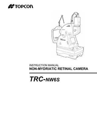
INSTRUCTION MANUAL
NON-MYDRIATIC RETINAL CAMERA
TRC-NW6S
INTRODUCTION Thank you for purchasing the TOPCON TRC-NW6S Non-Mydriatic Retinal Camera.
This machine has the following innovative features: • Can observe the fundus of the eye and take images without using mydriatics. • The quality of pictures has improved and this instrument is easier to operate than previous models. • Can easily take images of the periphery using the alignment point and the external fixation target for peripheral photography.
This manual outlines the TRC-NW6S Non-Mydriatic Retinal Camera, including operation procedures, troubleshooting, maintenance and cleaning. Before using, carefully read the “DISPLAY FOR SAFE USE” and the “SAFETY CAUTIONS” to familiarize yourself with the features of the TRC-NW6S NonMydriatic Retinal Camera and use it efficiently and safely. Always keep this Instruction Manual at hand.
PRECAUTIONS • Since this machine is a precision instrument, be sure to install and use it in a controlled environment under normal temperature, humidity and atmospheric pressure conditions (10~40°C, 30-85%, 70~106kPa) and avoid direct exposure to sunlight. • Never install the machine on a slope or a place with vibrations. • Before using the machine, make sure that all cables are correctly connected. • Use a power supply within the range of ±10% of the rated voltage (50/60Hz). • Keep the installation place always clean, and when not in use, turn off the Power switch, cap the objective lens, and install the dust cover. • To ensure good imaging results, handle the objective lens with particular care and keep it free of flaws, fingerprints, stains and dusts.
1
DISPLAY FOR SAFE USE To encourage safe and proper use and to prevent danger to the operator and others or potential damage to properties, important messages are put on the instrument body and inserted in the instruction manual. We suggest that everyone understand the meaning of the following displays, icons and text before reading the “SAFETY CAUTIONS” and observe all listed instructions.
DISPLAYS Display
Meaning
WARNING
Incorrect handling by ignoring this display may lead to an impending danger of death or serious injury.
CAUTION
Incorrect handling by ignoring this display may lead to personal injury or physical damage.
• Injury refers to hurt, burns, electric shock, etc. which does not require hospitalization or extended medical treatment. • Physical damage refers to extensive damage to the building, nearby equipment and/or surrounding furniture.
ICONS Icon
Meaning Prohibition. Specific content is expressed with words or a picture near the icon. Mandatory Action Specific content is expressed with words or a picture near the icon. Caution Specific content is expressed with words or a picture near the icon.
2
SAFETY CAUTIONS WARNINGS Icon
Prevention item
Page
To avoid electric shock, be sure to unplug the power cable before assembling. Also, do not plug the power cable before assembling.
14
To avoid fire and electric shock in case of leakage, be sure to use a power supply equipped with a 3-plug AC receptacle for proper grounding.
19
To avoid electric shock, do not attempt disassembling, rebuilding and/or repairs. Ask your dealer for repairs.
56
To avoid electric shock do not remove body components, covers of the TV relay lens, chinrest and power supply. – other than the lamp house cover.
56
To avoid electric shock, be sure to remove the power cable from the instrument body before removing the fuse cover. Also, do not connect the power cable to the instrument body with the fuse cover left unfixed.
64
To avoid fire and electric shock, install the instrument in a place free from water and other liquids.
-
To avoid fire and electric shock, do not put cups and vessels containing liquids near the instrument.
-
To avoid electric shock, do not insert metals into any vents and/or slots.
-
To avoid fire, use a properly rated fuse which matches the display provided on the fuse holder.
64
To avoid fire in the event of instrument malfunction, including smoke, immediately turn OFF the Power switch and unplug the cable.
-
3
SAFETY CAUTIONS CAUTIONS Icon
4
Meaning
Page
To avoid pain to the patient and damage to the patient’s eye, do not brighten the monitor lamp more than necessary.
45
To avoid pain to the patient and damage to the patient’s eye, do not brighten the photography light more than
45
To prevent the instrument from falling and to avoid injury, do not install the instrument on an unstable place, including a slope.
14 18 60
To avoid injury, do not put fingers into the gap between the instrument body and the power supply unit.
47
To avoid burn, do not touch the lamp immediately after it goes off.
61
To avoid electric shock, do not handle plugs with wet fingers
19
To avoid electric shock, do not touch the xenon lamp immediately flashes or burns out.
62
SAFETY CAUTIONS CAUTIONS Icon
Meaning
Page
To avoid injury to the patient’s face and hands, be sure to operate the chinrest for height adjustment while directly watching the patient.
41
To avoid injury to the patient’s eyes and nose while moving the instrument body, be attentive of the distance between the patient and the objective lens.
47
To prevent the TV relay lens and TV camera from falling and to avoid injury during adjustment and operation, make sure they are surely mounted. To avoid falling and injury while moving the table with the instrument on top of it, be sure to use an approved automatic instrument table.
16 18
To prevent the instrument from falling and to avoid injury during carrying, be sure to secure the instrument with the fixing knob at the bottom.
18
To avoid injury during carrying, be sure to hold the instrument body at the bottom with two persons. Carrying by one person may cause backache or injury by falling. Holding at areas other than the bottom may also cause pinching fingers and injury, as well as falling, thereby causing damage to the instrument.
14,18
To prevent the TV camera from falling and to avoid injury, make sure that the camera mount lever is firmly tightened.
60
To prevent the TV relay lens from falling and to avoid injury, make sure that the lens mount lever is firmly tightened.
60
To avoid electric shock, be sure to turn the power supply off and unplug the power cable before replacing the lamp.
61,62
To prevent the instrument body from falling and to avoid injury during movement, be sure to fix the power supply unit with the instrument body using the base locking knob.
-
5
USAGE AND MAINTENANCE Usage: • The TRC-NW6S Non-Mydriatic Retinal Camera is an electric instrument for medical use. Use this instrument under a doctor’s guidance.
USER MAINTENANCE: To ensure the safety and performance of the instrument, all maintenance work, unless specified in this manual, shall be conducted by trained service engineers. The following maintenance tasks may be done by the user. For details, see the relevant part of this manual. Replacing lamps: The illumination lamp and xenon lamp may be replaced by the user. For details, see “Replacing the illumination lamp” on page 61 and “Replacing the xenon lamp” on page 62. Replacing fuses: Fuses of the instrument body may be replaced by the user. “Changing the fuses” on page 64. Cleaning the objective lens: The objective lens may be cleaned by the user. objective lens” on page 66.
For details, see
For details, see “Cleaning the
ESCAPE CLAUSES • TOPCON shall not take any responsibility for damage due to fire, earthquakes, actions by third persons and other accidents, or damage due to negligence and misuse by the user and any use under unusual conditions. • TOPCON shall not take any responsibility for damage derived from inability to properly use this instrument, such as loss of business profit and suspension of business. • TOPCON shall not take any responsibility for damage caused from using this instrument in a manner other than that described in this Instruction Manual. • Diagnoses made shall be the responsibility of pertaining doctors and TOPCON shall not take any responsibility for the results of such diagnoses.
6
WARNING DISPLAYS AND POSITIONS To ensure safety, the machine provides warning displays. Use the instrument correctly by observing the display instructions. If any of the following display labels are missing, contact your dealer of TOPCON at the address stated on the back cover.
CAUTION • To avoid injury to the patient’s face and hands, be sure to operate the chinrest for height adjustment while directly watching the patient.
CAUTION • To avoid potential injury during operation, do not touch the patient’s eyes or nose with the instrument.
WARNING • Electrical shock may cause burns or possible fire. Turn the main power switch OFF and UNPLUG the power cord before replacing fuses. Replace only with fuses of the correct rating.
CAUTION • To avoid electric shock, be sure to turn the power supply off and unplug the power cable before replacing the lamp. • To avoid burn, do not touch the lamp immediately after it goes off.
WARNING WARNING • Electrical shock may cause burns or possible fire. Turn the main power switch OFF and UNPLUG the power cord before replacing fuses. Replace only with fuses of the correct rating.
• To prevent electrical shock, do not remove cover. No user serviceable parts inside, refer servicing to qualified personnel.
7
CONTENTS Introduction Display for safe use Safety Cautions Usage and Maintenance Warning displays and positions
1 2 3 6 7
Control panel components Monitor screen Standard accessories
9 10 11 12
ASSEMBLY Components
Connecting the TV relay lens with the instrument body Confirmation after assembling
13
Connecting the power cable Connecting the external device Menu setting Reset from power save state
14
Setting the record/playback mode Setting the fixation target Setting peripheral photography Setting the screen display System setting Setting the initial state Setting the language
8
Anterior segment photography
BEFORE REQUESTING SERVICE Troubleshooting Emergency chinrest operation Optional accessories
56 58
16 17 18 19 19 22 25 26 27 28 30 32 35 36 40
59 59
MAINTENANCE Daily checkups
INITIAL SETTING Preparation for initial setting
Peripheral photography
Specifications
PREPARATIONS Installing the instrument
Color photography (Center)
41 44 52 54 55
REFERENCES
ASSEMBLY PROCEDURE Assembling the instrument body
Preparation for photography
Finishing
COMPONENTS Component names
BASIC OPERATIONS
Cleaning
60 66
COMPONENTS COMPONENT NAMES TV camera connection terminal
Diopter compensation lens selector
TV relay lens attaching lever TV relay lens Angle selector
Focusing knob
Name plate slot Color video monitor Photography switch Omni-directional joystick
IR filter selector Image quality adjustment knob Base brake knob Vertical position mark
Control panel Power lamp
Fuse holder
Fixing knob (for carrying) Forehead rest
Anterior segment fixation target
Canthus marker
Objective lens Lamp house cover screw
Chinrest tissue pin Chinrest Lamp house cover
External fixation target
Base Power switch Fuse holder Power supply unit External connection terminal
9 COMPONENTS
CONTROL PANEL COMPONENTS Menu switch
Split switch
Flash Level switch (–, reset, +) Illumination Level switch (–, +)
Periphery Fixation switch (left turn, reset, right turn)
Chinrest switch (down, up)
Menu switch ... Displays the Menu screen. Split switch ... Turns split lines on/off. Flash Level switch ... Adjusts the flash level for the patient’s eye condition. Illumination Level switch ... Adjusts the illumination level for the patient’s eye condition. Chinrest switch ... Positions the patient’s head by electrically moving the chinrest up/down. Periphery Fixation switch... Switches the position of the internal fixation target to guide the patient’s eye to the periphery fixation point.
10 COMPONENTS
MONITOR SCREEN Monitor screen Nameplate/Fixation target position data
( ) scale
Xenon charging display Flash level compensation display Flash level display Picture angle display Fixation target position display
Alignment bright spots Split lines
Illumination level
Menu screen
Cursor
Input guide display
Preview display (color) Nameplate/ Fixation target position data
Photography image
11 COMPONENTS
STANDARD ACCESSORIES Upon unpacking, make sure that all the following standard accessories are delivered. Figures in ( ) are the quantities Power cable (1)
Nameplate (10)
Illumination lamp (1)
Fuse (9)
Chinrest tissue (1)
Chinrest tissue pin (2)
Emergency chinrest knob (1)
Spare parts case (1)
Instruction Manual
Warranty (1)
Dust cover (1)
External fixation target (1)
TV camera power cable (1)
TV camera signal cable (1)
12 COMPONENTS
ASSEMBLY COMPONENTS (1) (2)
(3)
(6)
(4)
(7)
(5)
(9)
(11)
(14)
(10)
(12)
(15)
(8)
(17)
(18)
(19) (16)
(13)
Description (1) Instrument body (2) TV relay lens (3) Rail cover (4) TV camera power cable (5) TV camera signal cable (6) Power cable (7) External fixation target (8) Star screwdriver (9) Hexagon rod spanner (10) Focusing tool
Quantity 1 1 2 1 1 1 1 1 1 1
(20)
Container O O O O O O O O O Spare parts case
Description (11) Dust cover (12) Spare part case (13) Illumination lamp (14) Nameplate (15) Fuse (spare) (16) Chinrest tissue (17) Chinrest tissue pin (spare) (18) Emergency chinrest knob (19) TRC-NW6SF Instruction Manual (20) Warranty
Quantity 1 1 1 10 9 1 2 1 1 1
Container O O Spare parts case Spare parts case Spare parts case Spare parts case Spare parts case Spare parts case
O O
13 ASSEMBLY
ASSEMBLY PROCEDURE ASSEMBLING THE INSTRUMENT BODY WARNING
To avoid electric shock, be sure to unplug the power cable before assembling. Also, do not plug the power cable before assembling.
CAUTION
To prevent the instrument from falling and to avoid injury, do not install the instrument on an unstable place, including a slope.
CAUTION
To avoid injury during carrying, be sure to hold the instrument body at the bottom with two persons. Carrying by one person may cause backache or injury by falling. Holding at areas other than the bottom may also cause pinching fingers and injury, as well as falling, thereby causing damage to the instrument.
NOTE
Since the upper part and lower part of the instrument body are merely connected with the power cable, take them out together so they do not separate from each other.
1 Take out the instrument body (1) from the container and put it on the table. 2 Slightly raise the omni-directional joystick, and pull out the cushion from the lower part of the base in the arrow direction.
Omni-directional joystick sponge
styrofoam
sponge cushion
3 Wipe the sliding board with a cloth to remove dirt.
14 ASSEMBLY PROCEDURE
4 Remove the styrofoam from the transportation bracket (A), the one on the left hand side viewed from the patient side, and unscrew the bracket (B).
transportation bracket (A)
transportation bracket (B)
5 Slide the base to the right and unscrew the transportation bracket (A). 6 Fasten the rail covers(3), using the small screws that are attached.
7 Set the external fixation target (7). Match the connector groove of the external fixation target (7) with the connector of the instrument body and insert it. Secure it firmly so that it does not move.
8 Fix the chinrest tissue(16) with the chinrest tissue pin.
chinrest tissue pin chinrest tissue
15 ASSEMBLY PROCEDURE
CONNECTING THE TV RELAY LENS WITH THE INSTRUMENT BODY CAUTION
To prevent the TV relay lens and TV camera from falling and to avoid injury during adjustment and operation, make sure they are surely mounted.
This machine is connected and used with an optional TV camera. If your TV camera is SONY DXC-970MD, the attached TV camera power cable (4) and TV camera signal cable (5) can be connected to the instrument body (1).
1 Turn the TV camera fixing ring in the arrow direction until it stops at the stopper, and remove the protective cap.
lens fixing ring protective cap
2 Mount the TV camera so the lens positioning hole matches the pin of the TV relay lens (2).
3 Turn the lens fixing ring in the arrow direction and fasten it.
16 ASSEMBLY PROCEDURE
CONFIRMATION AFTER ASSEMBLING
1 Slide the base to the left, as viewed from the operator side, and make sure that the primary voltage coincides with the voltage as set by voltage selector.
2 Make sure that the input voltage is within the range ±10% of the rated voltage. If the input voltage exceeds the range, use a constant-voltage power supply (marketed: 400VA up).
3 Loosen the base locking knob, and move the omni-directional joystick to confirm that it moves smoothly. 1) Right-left movement 2) Back-forth movement 3) Up-down movement
Just after being unpacked, the right-left movement may be uneven. If so, move the joystick with force to its limits in all directions.
17 ASSEMBLY PROCEDURE
PREPARATIONS INSTALLING THE INSTRUMENT CAUTION
To prevent the instrument from falling and to avoid injury during carrying, be sure to secure the instrument with the fixing knob at the bottom.
CAUTION
To avoid injury during carrying, be sure to hold the instrument body at the bottom with two persons. Carrying by one person may cause backache or injury by falling. Holding at areas other than the bottom may also cause pinching fingers and injury, as well as falling, thereby causing damage to the instrument.
CAUTION
To avoid falling and injury while moving the table with the instrument on top of it, be sure to use an approved automatic instrument table.
To prevent the instrument from falling and to avoid injury, do not install the instrument on an unstable place, including a slope. Fasten the fixing knob.
CAUTION
1 2 Firmly hold the instrument body at the specified positions, and put it on the automatic instrument table. For details about the automatic instrument table, see “OPTIONAL ACCESSORIES” on page 59.
Fixing knob Holding positions
Holding the instrument body
3 After installing the instrument, fully loosen the fixing knob. The instrument body is freed to move.
18 PREPARATIONS
4 If the instrument body is slightly off level, fine-adjust the height by properly operating the four adjusters. Do not extend the adjuster past 1cm.
Adjuster
CONNECTING THE POWER CABLE WARNING
To avoid fire and electric shock in case of leakage, be sure to use a power supply equipped with a 3-plug AC receptacle for proper grounding.
CAUTION
To avoid electric shock, do not handle plugs with wet fingers.
1 Make sure that the POWER SWITCH of the instrument body is OFF. 2 Attach the power cable to the instrument body.
3 Plug the power cable into the 3-p AC receptacle with grounding. CONNECTING THE EXTERNAL DEVICE Connecting the TV camera This machine is connected and used with an optional TV camera. If your TV camera is SONY DXC-970MD, the attached TV camera power cable and TV camera signal cable can be connected to the instrument body.
1 Connect the TV camera connection terminal of the instrument body and the DC IN/REMOTE terminal of the TV camera with the TV camera power cable.
19 PREPARATIONS