Operators Manual
71 Pages
Preview
Page 1
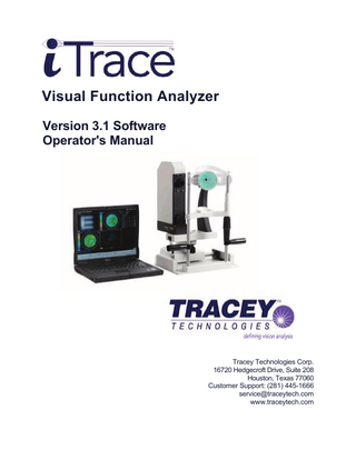
Visual Function Analyzer Version 3.1 Software Operator's Manual
Tracey Technologies Corp. 16720 Hedgecroft Drive, Suite 208 Houston, Texas 77060 Customer Support: (281) 445-1666 [email protected] www.traceytech.com
Copyright Notice Copyright © 2006, Tracey Technologies Corp. All rights reserved. No part of this manual may be reproduced without permission from Tracey Technologies Corp. Trademarks Microsoft Windows and Windows XP are trademarks of Microsoft Corporation.
2
General Warnings Important! Always follow these instructions to help guard against personal injury and damage to your Tracey iTrace Visual Function Analyzer system.
NOTE: The User(s) of the Tracey iTrace are responsible for ANY and ALL interpretations, diagnosis, and treatment plans using the data generated by the Tracey iTrace.
The Tracey iTrace Visual Function Analyzer is a Class I device. It contains a Class IIIb laser with a 785 nm output. To avoid inadvertent exposure to laser radiation, never operate the system with the covers opened or removed. Doing so may expose the user or others to stray laser radiation. Any service requiring access to the interior of the system should be performed only by Tracey Technologies authorized personnel or agents who have received specific system training. Operate the external computer and peripheral devices and all computer software following all guidelines supplied by the computer and software manufacturer or supplier. Operate the Tracey iTrace Visual Function Analyzer only from the type of power source indicated on the product-rating label. Carefully read all instructions prior to use. Retain all safety and operating instructions for future use. Observe all contra indications, warnings, and precautions noted in this manual.
3
Table of Contents CHAPTER 1 GETTING STARTED ... 6 WELCOME NEW USER ... 6 GETTING HELP ... 7 WARRANTY INFORMATION ... 7 CHAPTER 2 GETTING TO KNOW YOUR SYSTEM ... 8 DATA ACQUISITION UNIT - DAU ... 8 EYESYS VISTA HAND-HELD CORNEAL TOPOGRAPHER... 9 WF/CT ALIGNMENT ... 9 CLEANING AND MAINTENANCE ... 9 OPTOMETER...9 E-BOX...10 COMPUTER...10 DATA STORAGE ... 10 CHAPTER 3 LEARNING THE BASICS ... 11 NEW USER INSTALLATION AND TRAINING ... 11 INSTALLING YOUR TRACEY iTrace SOFTWARE ... 12 SPECIAL FUNCTION KEYS... 14 TO USE A JOYSTICK ... 15 TO PRINT A SCREEN... 15 TO SAVE A DISPLAY... 15 TO CHANGE DISPLAY TYPE... 16 TO CHANGE DISPLAY SIZE ... 17 TO CHANGE DISPLAY METHOD ... 17 TO CHANGE DISPLAY ELEMENT……………………………………………………………….18 TO CHANGE ZONE ... 19 TO COMPARE ABERRATIONS ... 19 POWERING SYSTEM ON AND OFF ... 20 CHAPTER 4 NEW AND EXISTING PATIENTS ... 21 KEY FEATURES... 22 TO CREATE A NEW DATABASE ... 23 TO CHANGE A DATABASE FILE ... 24 TO ADD NEW PATIENT ... 24 TO EDIT PATIENT’ DATA ... 25 TO DELETE A PATIENT ... 25 TO COPY PATIENT’ DATA... 26 TO SEARCH A PATIENT ... 27 TO EDIT PREFERENCES FILE ... 28
4
CHAPTER 5 THE EXAMINATION PROCESS ... 29 CAPTURING A WAVEFRONT EXAM ... 29 FOCUSING AND PROCESSING ... 29 VERIFYING A WF EXAM ... 32 SAVING THE EXAM ... 37 RETAKING THE EXAM ... 37 TAKING A CT EXAM ... 38 CHAPTER 6 PATIENT EXAM REVIEW ... 40 TO VIEW A PATIENT’ EXAM ... 40 TO SELECT WF OR CT EXAMS ... 41 TO DISPLAY A MULTI-EXAM ... 41 MULTI-EXAM OPTIONS MENU ... 43 TO VIEW TWO-EXAM ... 44 TO VIEW WF AND CT SUMMARY ... 45 WF VERIFICATION DISPLAY... 46 WF VERIFICATION OPTIONS MENU ... 47 WF SUMMARY DISPLAY ... 48 WF SUMMARY OPTIONS MENU ... 49 WF COMPARISON DISPLAY ... 51 CT VERIFICATION DISPLAY ... 52 CT VERIFICATION OPTIONS MENU ... 52 CT SUMMARY DISPLAY... 53 CT SUMMARY OPTIONS MENU... 54 CT COMPARISON DISPLAY ... 55 APPENDIX A INSTALLATION INSTRUCTIONS ... 56 VERIFY PACKAGING ... 56 TRACEY SETUP ... 57 CHINREST ASSEMBLY ... 57 DUAL MOUNT SLIDER ASSEMBLY ... 58 MANIPULATOR FINAL ASSEMBLY ... 58 FINAL CONNECTIONS ... 59 ITRACE USER TRAINING CHECK LIST ... 60 APPENDIX B TECHNICAL INFORMA TION... 61 MAP LAYERS ... 61 DISPLAY TYPES ... 61 APPENDIX C CD OPERATIONS... 63 BACKUP ACCESS DATABASE OF PATIENTS ... 63 STAND ALONE SOFTWARE ... 63 APPENDIX D ZERNIKE MODES CHART... 64 GLOSSARY... 65 SOFTWARE LICENSE AND WARRANTY STATEMENT ... 67
5
Chapter 1
Getting Started
Please read the Operator's Manual in its entirety before using your Tracey iTrace System.
Welcome New User Congratulations on acquiring your new Tracey iTrace Visual Function Analyzer (iTrace). Chapter 2 acquaints you with your systems hardware: the data acquisition unit (DAU), the computer, and printer. Chapter 3 covers the basics of using your system, from powering on and off to using your iTrace software and working with the screens. Chapter 4 of this manual reviews how to examine patients and keep track of your data. With your new iTrace, you will now have the ability to look at the entire refraction of the eye with the highest level of objective measure and detail. In fact, viewing a refractive map of the entrance pupil which covers the refractive power of the entire eye on a point-by-point basis, as opposed to the basic refractive numeric summary of sphere and cylinder, will have an enormous impact on your practice in terms of speed, accuracy and the clinical care of your patients. To measure refraction on a spatially resolved basis requires the ability to look at the wavefront aberrations of the eye on a point-by-point basis. The iTrace actually analyzes light that is directed into the eye focused onto the retina creating a secondary light source as it is reflected from the retinal surface and projected out the exit pupil. The iTrace uses the fundamental thin beam principle of optical ray tracing to measure the refractive power of the eye on a point-by-point basis. The simplicity of measuring one point in the entrance pupil at a time is unique to the Tracey system. Your iTrace system is designed to very rapidly fire a series of very small parallel light beams one at a time, within microseconds into the entrance pupil. These beams of light pass through the entrance pupil of the eye in an infinite selection of software selectable patterns. With new designs of the photo detector system, iTrace can easily measure a large dynamic range of aberrations and maintain high resolution. This should provide for a significant advantage when measuring a physiologic system, such as the eye, which can easily have a tremendous range of refractive errors. Additionally, since each point is sequentially measured there is never any confusion of which entrance pupil location registers with the retinal spot detected. As the iTrace system directly measures the point spread function of the eye with its retinal spot detection, it can then easily provide for full calculation of wavefront deformation of the eye.
6
Your iTrace system captures and processes corneal topography data using the EyeSys Vista Hand-held Corneal Topographer. Wavefront data of the cornea is combined with wavefront data of the eye to obtain the industry's first-ever lenticular aberration analysis.
Getting Help Help screens will be added to the software in the next release. Telephone Support is available by calling (281) 445-1666. Questions may be submitted via E-mail to [email protected] Or by fax to (281) 445-3050.
Warranty Information Your Tracey system comes with a standard one-year warranty for parts and labor on the components purchased from Tracey Technologies including software updates (see warranty information in the back of this manual). Extended Service Agreements are available from Tracey Technologies. Contact your sales representative or Tracey Technologies at (832) 2951605 for more information.
NOTE:
The User(s) of the Tracey iTrace are Responsible for ANY and ALL interpretations, diagnosis, and treatment plans using the data generated by the Tracey iTrace.
7
Chapter 2 Getting to Know Your System The Tracey iTrace Visual Function Analyzer provides the ability to offer your patients accurate, repeatable, and prompt refractive measurements of the complete optical system in the eye. The iTrace performs these primary tasks: • Captures an eye image • Measures 256 points within the patient's entrance pupil • Generates numerous customized displays to view the data • Saves exam data in an organized database • Automatically centers, sizes the scan pattern within the pupil, and captures the data • Verifies focus and alignment • Prints any of the provided displays • Saves displays as bitmap files • Combines corneal wavefront data and total eye wavefront data to generate a lenticular aberration analysis The system also has provisions for these functions: • Displaying and analyzing exam data in user-defined custom formats • Setting and changing system parameters • Patient database management This chapter describes the primary components of your system: the Data Acquisition Unit, the Vista Corneal Topography Unit, the E-Box, the external computer, and the data storage recommendation. Chapter 3 discusses the basics of using your system, and navigating around the menus.
Data Acquisition Unit - DAU This component is used to project and record the points of light as they enter through the pupil and focus on the retina. The iTrace software uses these data points to produce the various displays. The Data Acquisition Unit (DAU) features an adjustable focusing target, pupil size detector, and an OD/OS detector. The DAU consists of a single rectangular module mounted onto the chin rest power base.
8
Getting to Know Your System
EyeSys Vista Corneal Topographer This component is a Placido-based corneal topography analyzer. It connects to the iTrace EBox using the supplied phone cable. The backlighted Placido rings are projected onto the corneal tear film, and the image is auto-captured when device is at the proper working distance and the projected laser beam is centered in the live video image. The iTrace software then defines the ring edges and calculates corneal curvature, corneal refractive power, and corneal wavefront data.
WF or CT Alignment Before taking a WF or CT exam, please make sure the iTrace optometer is aligned with the joystick for the WF exam, or the Vista is aligned with the joystick for the CT exam. WF
CT
Cleaning and Maintenance The exterior of these units may be cleaned with a dry cloth. Avoid getting any moisture or liquid on/in the system. DO NOT touch the optics inside the eyepiece. If necessary, compressed air may be used to remove dust inside the optical eyepiece. BEFORE using the air, power the system off.
Optometer The optometer is the black saxophone-shaped component attached to the DAU on the technician's side. This component is the fixation device for alignment of the patient’s line of sight with the laser axis. It also is for relaxing the patient's accommodation and by providing a target of increasing/decreasing spherical correction from +7 to -5 D primarily. It is removable by loosening the two thumbscrews for open view measurements. The optometer may be removed or replaced while the system is turned on, EXCEPT during the actual acquisition process. PLEASE HANDLE THE OPTOMETER WITH EXTREME CARE TO MAINTAIN TARGET ALIGNMENT
9
Getting to Know Your System
E-Box
The E-Box is the base unit into which all power cables, USB cable, Vista topographer cable, and the data transfer cables from the DAU connect. This unit contains the power supply, data transmission and image capture processing boards. This unit is not serviceable by the customer, and only trained Tracy service engineers should work on this component.
Computer The computer is an external computer (laptop or desktop model) supplied by Tracey or by the customer. Laptop/Desktop computers must meet these minimum specifications*: • CPU: Intel Pentium or Celeron processor with minimum 2.0 GHz speed • 512 MB RAM (Main Memory) • CD-RW or DVD±R Multi-function Drive • HD Capacity: 40GB Minimum • 2 USB 2.0 Ports for connecting iTrace acquisition unit and color printer • Integrated 10/100 Ethernet LAN • Microsoft Windows XP Home or Pro Operating System • Color Printer (USB or wireless) for Printing Displays • (Optional) Parallel Port for EyeSys Vista Base connection (only if base is purchased separately from EyeSys Vision) Our tests have shown excellent result with the following preferred computer manufacturers: Acer, HP and Toshiba. *These specifications are subject to change. Data Storage Recommendation Tracey recommends that you backup your patient file databases using the CD-RW or DVD±R Multi-function drive. In case of a computer hardware failure or database corruption, your patient files can be restored readily. 10
Chapter 3
Learning the Basics
This chapter covers the basics of using the iTrace software. Chapter 3 is especially helpful for new computer users to get you going quickly on your new system. This chapter includes the following topics: New User Installation and Training Install your iTrace Software Special keyboard keys Using the Joystick Printing a screen Saving a display Using common display options Powering system on and off
New User Installation and Training A Tracey-certified installation representative will install your new iTrace system and verify calibration. You then will receive training from a Tracey-certified training specialist. Training on the iTrace and its software should take approximately 2 hours, however be prepared to spend a significant portion of the day with the training specialist learning to operate the iTrace software and equipment. If possible, it can be helpful to schedule some patients for an actual examination near the end of training. The training specialist will do the following: Explain the hardware components Train you on the operation of the hardware and software Train you on the iTrace exam process Train you on the Vista Corneal Topographer exam process Explain the different displays Explain how to customize displays based on your practice needs
11
Learning the Basics
To Install your iTrace software 1 Start your computer. Log on with your username. Your username must have administrator privileges to install new software. If not, please contact your system administrator for support.
2 Insert iTrace installation CD. 3 The software should install itself, if not, run Windows Explorer, click on the drive letter where the installation CD was inserted, and then run the file setup.bat. This installation procedure will: - create a desktop shortcut and a quick launch icon if so choose. - install and update necessary database drivers.
4 Power on the E-Box system. 5 Plug in USB cable. 6 Windows will find new hardware and bring up installation wizard for it. 7 Lets Windows find and install driver automatically.
If windows can’t find the driver, select this option and click Next
12
Learning the Basics
Select this option and type C:TraceyDrivers in the text box and click Next, Windows then will install the driver correctly.
8 Unplug USB cable. 9 Plug in USB cable. 10 Start iTrace 3.1.exe and wait until the cursor becomes an arrow. 11 Windows will find new hardware and bring up installation wizard for it again. 12 Unplug USB cable. 13 Plug in USB cable. 14 Close iTrace 3.1.exe application. 15 Start iTrace 3.1.exe application. NOTE
If Windows XP complains about the hardware does not meet compatibility test, please ignore this warning and click on Continue Anyway button to proceed with the installation.
13
Learning the Basics
Special function keys The iTrace program uses these special function keys frequently. use to move from field to field. The Shift + Tab combination keys move the cursor to the previous field.
use for moving the cursor to the left, right, up, and down. The cursor indicates your position in a text entry field and takes the form of a blinking vertical bar. The up and down arrow keys also are used for manually adjusting the scanning diameter in the pupil during the acquisition process. The right and left arrow keys also are used to manually adjust the target +/- diopter steps as set in the accommodation parameters. also known as the Return key, can be used in lieu of clicking OK. During acquisition process the ENTER key is used to toggle between Manual and Auto alignment functions for each exam. use in combination with other keys. For instance, CTRL + ESC means to hold down the CTRL key and then press the ESC key. use in conjunction with other keys. For instance, Shift + Tab means to hold down the Shift key and then press the Tab key. use to cancel the acquisition process. change the C4 (defocus) term on the Retinal Spot Diagram display. It simulates moving the retina forward and backward through the Conoid of Schturm use to reset the Retinal Spot Diagram after using F1/F2. use to provide continuous change in Retinal Spot Diagram over the range of +10 to -10 D of change. press to view the data point positions on the detector. Select any display button to exit. use to view the linear array signals for each sample point without filtering on. press to view simulated raw detector signals. reset target to 0 diopters 14
Learning the Basics
To Use the Joystick
The joystick is used to position the DAU or Vista CT in front of the patient's eye for data acquisition. The four operations performed by moving the joystick are listed below: To move the image left or right in small increments, move the joystick in the left or right direction. To move the image up or down, twist the joystick clockwise (up) or counter-clockwise (down). To focus the image in small increments, move the joystick to the forward or backward. To capture an image while in manual mode , press and release the acquisition button on top of the joystick.
To Print a screen There are 2 ways to print the entire screen. button on lower right corner. A Print 1.Click selection window appears for printer selection. Answer OK to print. Draft print quality, which can be selected through Properties button, will give the quickest printout. 2. On any display, right mouse click to get the Options Menu and select Print.
To Save a display You can save an entire screen or individual display in two ways. All graphics will be saved in BMP file format, except for the Zernike Coefficients saving option which will default to TXT file format. 1.Click
button on lower right corner to save the entire screen in BMP file.
2.On any display, right mouse click to get the Options Menu and select Save.
Depending on the display, you can have up to 4 save options; Entire Screen, This Window, Eye Image, and Zernike Coefficients. The first 3 options will save the display in BMP file format. While the latter saves the Zernike Coefficients in TXT file format, and then Notepad will open the saved TXT file for viewing. 15
Learning the Basics
Common display options
In a Verification or Summary display mode, the default screen contains 4 small displays. This display setting and others common default settings can be changed by right mouse click on any display to bring up the Options Menu and then select different options.
To View another display Select Display type from the Options Menu then choose another type.
16
Learning the Basics
To Enlarge a display Select “Large “option from Display size of the Options Menu. This will enlarge the display to fit the whole display area.
To View display in 3D The default display method is 2D. Display Method option is available only in Summary display mode by clicking on one of five Summary buttons. Right mouse-click to bring up the Options Menu, highlight Display Method and choose 3D.
3D
17
Learning the Basics
To Change display elements A display element is an overlay of image which you can layer together to help with your data analysis. Not all displays contain all the display elements. Some elements are only specific to that display. Perform a right mouse click on any display to bring up the Options Menu. Select Display Elements option and then choose a display element or all of them.
Eye image
Grid
WF map
Pupil
Corneal vertex
Scan points
CT rings
MTF map
CT map
18
Learning the Basics
To Select zone size You can choose different scan zone to view for the multizone refraction display though the default settings in the Preferences File. You can change the zone for viewing on any display by selecting the zone from the buttons across the bottom of the display. You can also bring up the Options Menu by right mouse click. Select Zone option and then choose the options. You can pick a distinct zone value from 2.0mm to 8.0mm, or Full Scan option for all the zones, and Other allows you to choose an arbitrary value.
To Compare aberrations Different aberration types can be selected by bring up the Options Menu. Highlight Aberrations option and then select the different types and the associated zones. Choose Other if you want to enter an arbitrary value. Choosing Other option in a RMS display will bring up the Aberrations Mask screen.
19
Learning the Basics
To Power the System On 1 verify all cable connections. 2 if using a surge protector, locate the power switch on the surge protector and move to the ON position.
3 locate the power switch on the Tracey E-box and place in the ON position. ON
4 locate the power switch on the printer and move to the ON position. 5 locate the power switch on the laptop or desktop computer and place in the ON position. 6 wait until computer has finished its boot-up process and shows the Windows XP desktop with all icons.
7 double click on the
icon on the Windows XP Desktop screen.
To Power the System Off: 1 Exit the iTrace program by repeat clicking
button on the lower right corner of the
iTrace screen until you get to the main menu screen, then click Yes to exit the program.
button. Confirm
2 move the power switch on left side of the iTrace E-Box to OFF. 3 remove and safely store any CD's from the computer 4 click the
button and select from the menu and in the pop-up window. The computer now will shut down.
option
5 if using a surge protector, place the surge protector power switch in the OFF position.
20